

Page 1
801 Avenida Acaso, Camarillo, Ca. 93012 • (805) 494-0622 •
8
www.sdcsecurity.com • E-mail: [email protected]
INSTALLATION INSTRUCTIONS
EA SERIES –DOOR PROP/EXIT ALARM
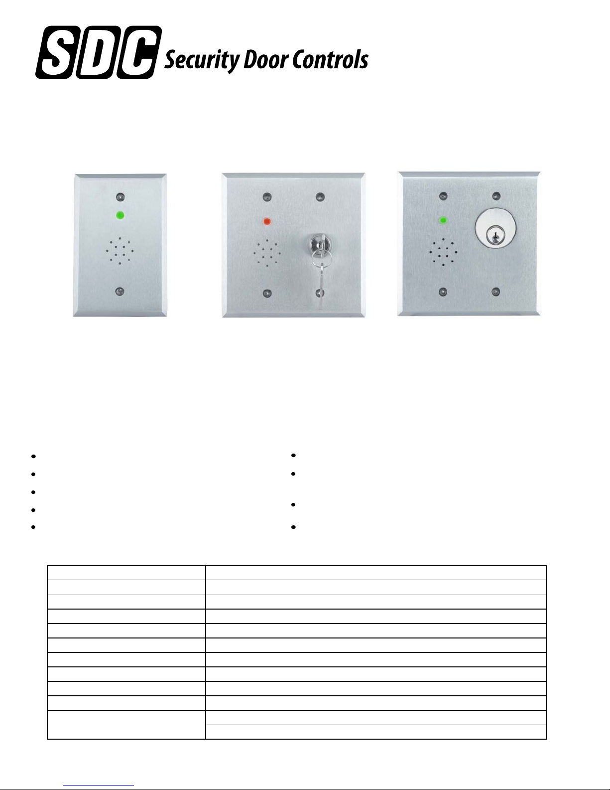
Model EA-SN Model EA-728
Model EA-708
(cylinder not included)
The SDC EA Series offers Exit Alarm, Forced Door Alarm, and Door Propped/Held Open Alarm monitoring
capabilities to any controlled opening. It may be used as a standalone device or easily integrates with any
access control system. Units are typically mounted adjacent to the opening, and provide local visual and
audible alarm annunciation. An integral key switch is available for local bypass & alarm reset controls. A
built-in alarm relay is also included for remote monitoring.
FEATURES
Exit alarm on door opening
Door prop alarm after adjustable timed delay
Manual or automatic alarm reset
Local 85dB Piezo buzzer alarm
Integral LED status indicator
EA SERIES TECHNICAL SPECIFICATIONS
Input Power: 60mA @ 12 or 24VDC (Auto-sensi ng)
Mounting: EA-SN: Single Gang, 1/4" Thick aluminum plate w/ security screws
(2-1/8" de pth recommended) EA-708, -728: Double Gang, 1/4" Thick aluminum plate w/ security screws
Alarm Sound Level: 85dB @ 3ft, Piezo Buzzer
Status Indicator: Bi-color LED
Trigge r (DPS) Input: Dry, N/C or N/O, field selectabl e
Reset/Bypass (Control) Input: Dry, N/O or N/C, field selectable
Alarm (Main) Output: Form C, 2A @ 30VDC (Resistive)
Auxiliary Output: Form C, 2A @ 30VDC (Resistive)
Wiring: Screw terminals
Overall Dimensions:
Main relay output for remote alarm notification
Auxiliary relay output for door position status or
bypass/alarm status
Optional key reset/bypass switch
Compact universal mounting
EA-SN: 5"h x 3.25"w x 1.625" d
EA-708, -72
: 5"h x 5"w x 1.875"d
P:\INSTALLATION INST\Accessories\INST-DOOR PROP.vsd Rev A 07-17 Page 1
Any suggestions or comments to this instruction or
product are welcome. Please contact us through
our website or email [email protected]
Page 2
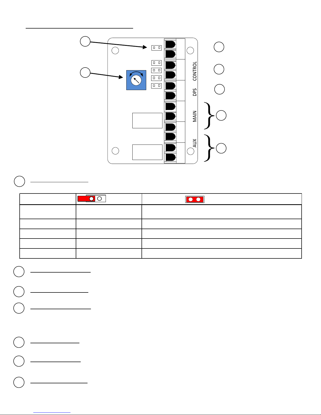
EA Series Board Layout (Back View):
1
1
2
2
1s 60s
Configuration Jumpers – Numbered 1 through 5. By default, all jumpers have been set to OFF. Use the (5)
1
supplied jumpers, as required. See the table below for a functional description of each jumper.
3
4
5
PWR (-)
PWR (+)
NO
C
NC
NO
C
NC
3
}
4
}
5
}
6
*The state of the Main & Aux. relays are
shown when the unit is not powered.
7
Configuration Jumpers
Disabled (Alarm resets on
1= Latchi ng A larm
2= Alarm Auto Re set Disable d Au to- rese t 60 sec. af ter door cl osure . (Requires Jumper #1 to be ON)
3= Control Input Pol arity Norm ally Ope n No rmally Close d
4= DP S Input Pol arity Normally Cl ose d No rmally Ope n
5= Aux. Re lay Functi on Foll ows DPS Input Fol l ows Bypass/Alarm State
Adjustable Alarm Timer – Determines the amount of time a door can be propped open before an alarm is
2
activated. Adjustable from 1 to 60 seconds. Turn clockwise to increase time.
Input Power Terminals – Requires a 12 or 24VDC +/- 10% power supply (auto-sensing).
3
Control Input Terminals – Dry input used for bypass & alarm reset. Field-selectable as normally open
4
(default) or normally closed. In a secure state, a held input will bypass the unit. In an alarm state, a
momentary input will reset the alarm providing the door is closed.
This input is factory pre-wired for key switch model EA-728.
Door Contact Input – Required for all models. Monitors the open/closed status of the door. Field-
5
selectable as normally open or normally closed (default).
door closure) Enabled. (Requires use of Control Input to reset an alarm OR Jumper #2)
Jumper OFF Jumper ON
Alarm Relay Output – Relay is energized when the unit is powered. An alarm state or loss of power will
6
de-energize the relay.
Auxiliary Relay Output – Relay may be configured to follow the DPS input OR to follow a bypass/alarm state.
7
P:\INSTALLATION INST\Accessories\INST-DOOR PROP.vsd Rev A 07-17 Page 2
Page 3
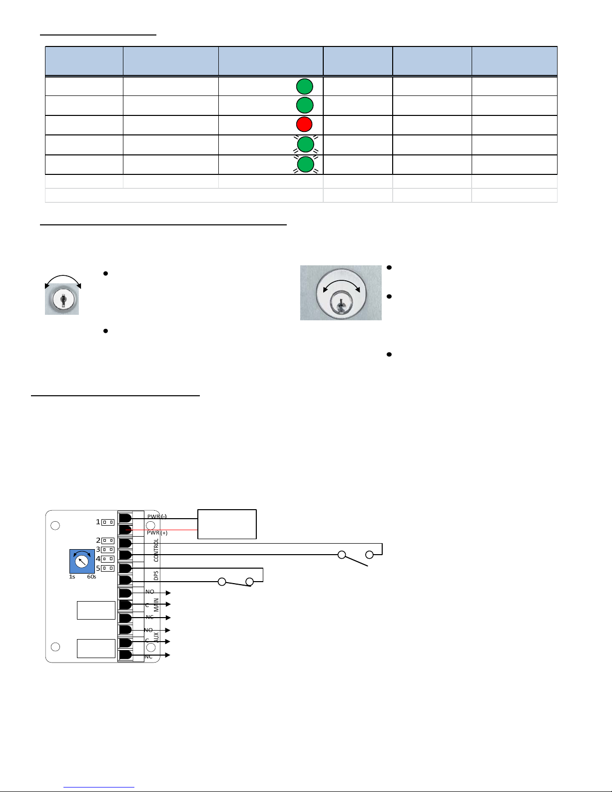
LED Status Indicator:
Aux. Relay*
Door Status Unit Condition LED Status Main Re lay
Closed Secure Solid Green Energized De-energized Energized
Open Pre-alarm (1-60 sec.) Solid Green Energized Energized Energized
Open Alarm Solid Red De-energized Energized De-energized
Closed Bypassed Flashing Green Energized De-energized De-energized
Open Bypassed Flashing Green Energized Energized De-energized
G
G
R
G
G
(Jumper 5 OFF)
Aux. Relay
(Jumper 5 ON)
*Relay state shown with N/C Door Contact
Key Switch Operation (EA-708 or 728 only):
NOTE: Unit must be Secure to be Bypassed. Door must be closed to reset an alarm condition.
See Page 5 for Mortise Key Cylinder
installation
Bypass (Maintained) –
Turn counter-clockwise until ON/OFF
switch is activated. Reactivate the
switch to re-secure.
Alarm Reset (Momentary) –
Turn clockwise until momentary
switch is activated.
By
s
s
a
p
R
e
s
e
t
Bypass (Maintained) –
90° Counter-clockwise.
Key may be removed. Return to
EA-728
vertical position to re-secure.
Alarm Reset (Momentary) –
45° Clockwise. Key returns to
vertical position upon release.
EA Series Operational Modes:
By
s
a
p
s
EA-708
R
e
s
e
t
Wiring Example #1 – Non-latching (auto-resetting) Exit Alarm or Door Prop Alarm. Opening
the door will initiate the pre-alarm timer. Closing the door before the timer expires resets the
timer. If the door remains open and the timer expires, an audible alarm will sound and the
Main Relay will trigger. Alarm resets on door closure. Bypass the alarm by activating the
integral key switch or via remote bypass switch.
12 or 24VDC
P.S.
N/C
Alarm Relay for
remote monitoring
Auxiliary Relay follow DPS input
(a) All jumpers are set OFF (default)
(b) Adjust the alarm delay timer (1-60 seconds), as required.
(c) Install & terminate a N/C door contact.
(d) Install & terminate optional output relays, as needed. See page 2 for relay descriptions.
(e) Apply power & test.
Power Supply:
SDC Model TR-12, TR-24, or 600 Series
N/O
Door Contact:
SDC Model MC-4 or similar
EA-SN: Optional Remote Bypass;
Pre-wired for model EA-728
P:\INSTALLATION INST\Accessories\INST-DOOR PROP.vsd Rev A 07-17 Page 3
Page 4
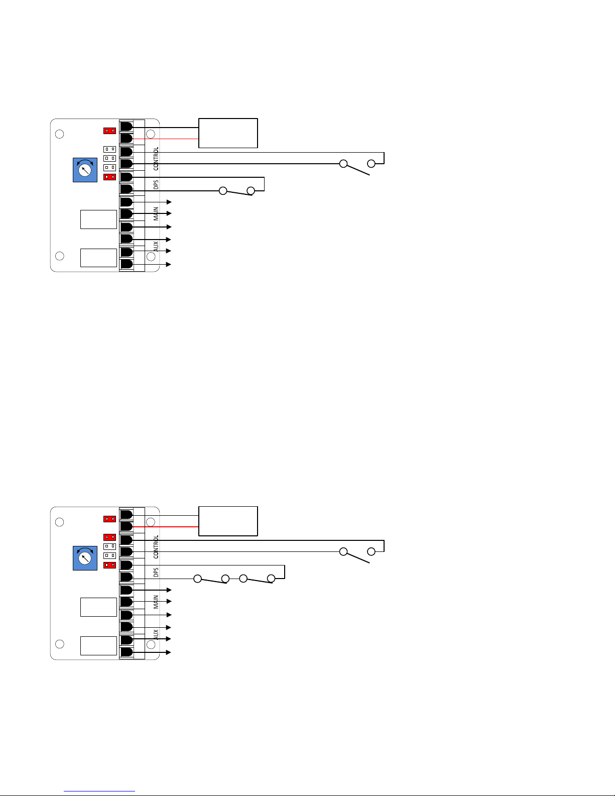
Wiring Example #2 – Latching (Manually Reset) Exit Alarm/Door Prop Alarm. Opening the door
will initiate the pre-alarm timer. Closing the door before the timer expires resets the timer. If the
door remains open and the timer expires, an audible alarm will sound and the Main Relay will
trigger & latch. Alarm must be reset by using the integral key switch (EA-708 or EA-728 only), or by
remote control switch. Bypass the alarm by activating the integral key switch or via remote switch.
1s 60s
1
2
3
4
5
PWR (-)
PWR (+)
NO
C
NC
NO
C
NC
12 or 24VDC
P.S.
N/C
Alarm Relay for
remote monitoring
Auxiliary Relay changes state when the unit
enters bypass mode or alarm mode
Power Supply:
SDC Model TR-12, TR-24, or 600 Series
N/O
Door Contact:
SDC Model MC-4 or similar
EA-SN: Requires Remote Reset Switch;
Pre-wired for model EA-728
(a) Jumpers 1 & 5 are installed. Jumpers 2, 3, & 4 are set OFF.
(b) Adjust the alarm delay timer (1-60 seconds), as required.
(c) Install Remote reset switch. Required for EA-SN; Optional for EA-708 or EA-728.
(d) Install & terminate a N/C door contact.
(e) Install & terminate optional output relays, as needed. See page 2 for relay descriptions.
(f) Apply power & test.
Wiring Example #3 – Double-Door Latching Exit Alarm/Door Prop Alarm with Timed Reset.
Opening the door will initiate the pre-alarm timer. Closing the door before the timer expires resets
the timer. If the door remains open and the timer expires, an audible alarm will sound and the
Main Relay will trigger & latch. The alarm will automatically reset 60 seconds after door closure.
The alarm may also be reset by using the integral key switch (EA-708 or EA-728 only), or by remote
control switch. Bypass the alarm by activating the integral key switch or via remote bypass switch.
1s 60s
1
2
3
4
5
PWR (-)
PWR (+)
NO
C
NC
NO
C
NC
12 or 24VDC
P.S.
N/C
Alarm Relay for
remote monitoring
Auxiliary Relay changes state when the unit
enters bypass mode or alarm mode
(a) Jumpers 1, 2 & 5 are installed. Jumpers 3 & 4 are set OFF.
(b) Adjust the alarm delay timer (1-60 seconds), as required.
(c) Install Remote reset switch. Required for EA-SN; Optional for EA-708 or EA-728.
(d) Install & terminate N/C door contacts in series.
(e) Install & terminate optional output relays, as needed. See page 2 for relay descriptions.
(f) Apply power & test.
P:\INSTALLATION INST\Accessories\INST-DOOR PROP.vsd Rev A 07-17 Page 4
Power Supply:
SDC Model TR-12, TR-24, or 600 Series
N/O
N/C
Door Contacts:
SDC Model MC-4 (x2)
EA-SN: Requires Remote Reset Switch;
Pre-wired for the EA-728
Page 5
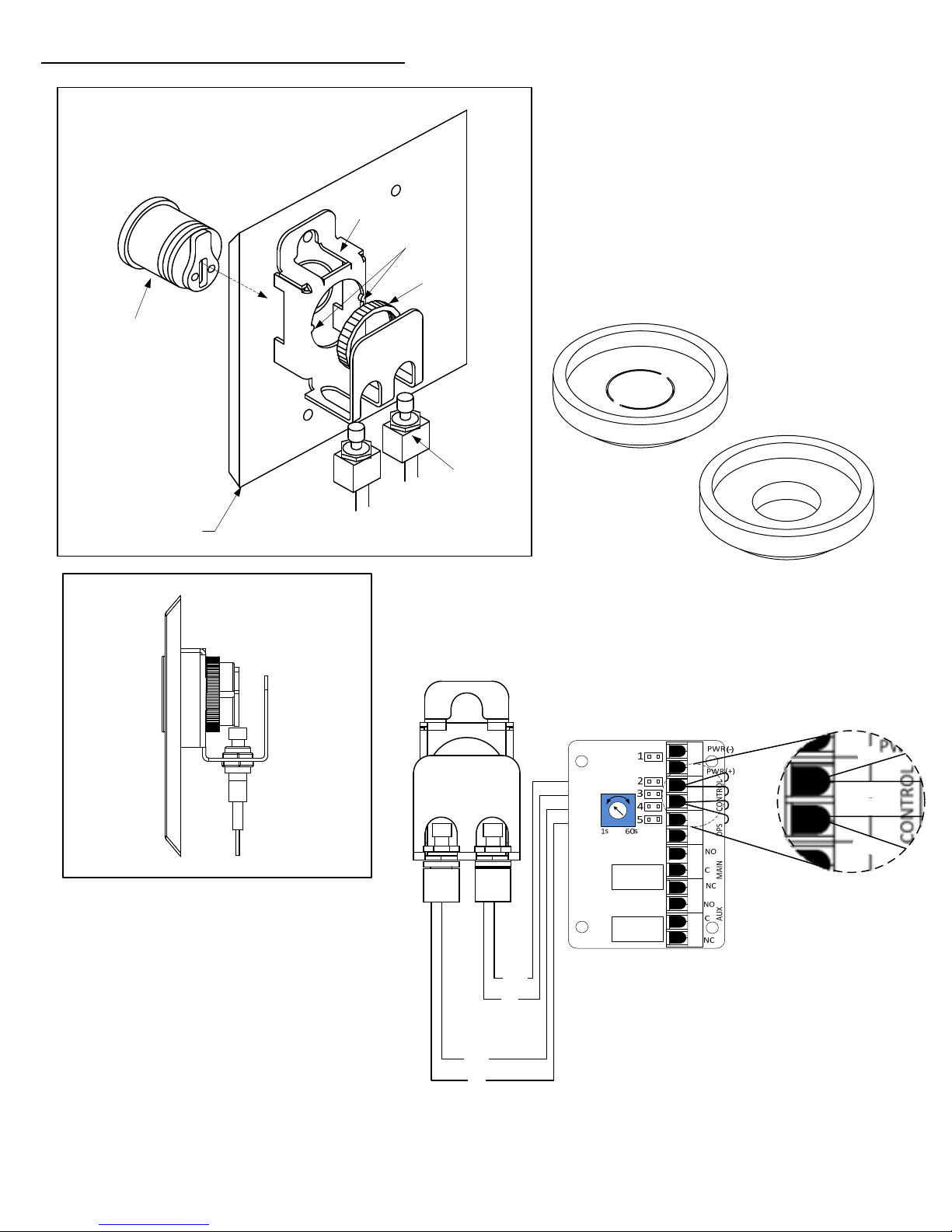
EA-708 Mortise Key Cylinder Installation:
ASSEMBLY DETAIL
Switch
Mounting
Bracket
Key Cylinder
SDC Part# CYL-KD
Or supply compatible 1” to
1-3/8” standard or
interchangeable core
mortise key cylinders (not
included)
Use tailpiece supplied with
SDC Part# CYL-KD, or Ilco
863G-00-10 Standard Cam
equivalent.
Faceplate
triangular
tabs
Locknut
Adjustable
Switch
Assembly
SOUND DAMPENER
All Exit Alarm Assemblies are shipped with a
sound dampening cap loose in the box.
Install the unit without the cap for full volume.
Install the unit with the cap as shipped for
complete dampening.
Install the unit with the center hole punched
out for partial dampening
CENTER HOLE
AS SHIPPED
CENTER HOLE
PUNCHED
Ensure that the cam makes
contact with the center of
the switch plunger
4. Complete the wiring connections by carefully routing the
(2) white & (2) yellow wire leads behind the board. Terminate
the (2) yellow wires to Control terminal “A”. Terminate the (2)
white wires to Control terminal “B”.
SWITCH WIRING
L
E
Y
A
YEL
(Reset)
(Bypass)
WHT
B
W
H
T
NO
COM
NO
COM
WHT
YEL
P:\INSTALLATION INST\Accessories\INST-DOOR PROP.vsd Rev A 07-17 Page 5
WHT
YEL
 Loading...