

Page 1
Security Door Controls
3580 Willow Lane, Westlake Village, CA 91361-4921 • (805) 494-0622 • Fax: (805) 494-8861
www.sdcsecurity.com • E-mail: [email protected]
PROGRAMMING INSTRUCTIONS
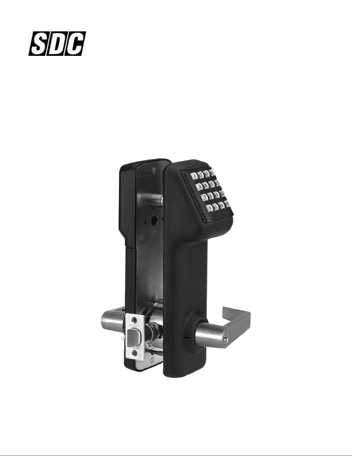
E72K-A CIVIC SERIES
160 User Electronic Digital Door Lock
P:\INSTALLATION INST\ELECTRIFIED LOCKSETS/INST-E72K-A/INST-E72K-A.vsd REV - 07-08 Page 1
Any suggestions or comments to this instruction or
product are welcome. Please contact us through
our website or email [email protected]
Page 2
IMPORTANT KEYS:
TERMINATOR KEY ( )
Acts like the “Enter” key on a computer, and is used to confirm entries on the keypad.
PROGRAMMING KEY (#)
After a valid Master Code is entered, this key is depressed to enter the programming mode.
NOTE: At the end of any programming series, replace the last with a # to return to function number input.
This allows the programmer to perform multiple functions without having to re-enter the Master Code for
each function.
*
*
LED INDICATOR:
LED INDICATING GREEN (NORMAL MODE):
1. Denotes lock enabled to open. Will flash green after valid entry and terminator key ( )
LED INDICATING RED (NORMAL MODE):
1. Denotes a wrong code entry.
2. Three consecutive wrong entries will disable keypad for 20 seconds. If another wrong code is entered, the keypad is
disabled for 40 seconds. This is indicated by a solid red light.
LED INDICATING RED (PROGRAMMING MODE):
1. Denotes incorrect entry and vacates the programming mode.
2. Programming mode vacated if no key entry within 5 seconds.
*
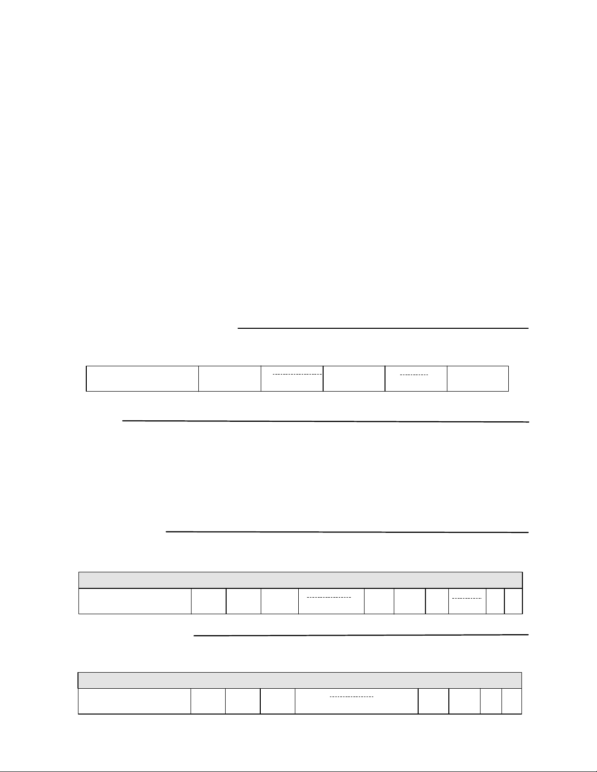
CREATE MASTER CODE
This code is required to perform all programming functions. The number of digits used for the User ID and PIN of each additional
user must be the same as the Master Code.
Enter 9991234
User ID and PIN followed by ( ) will open the lock.
*
*
*
(User ID)
#
(PIN)
#
GROUPS
ALL USERS MUST BE ASSIGNED TO A GROUP. Users in the same group will have the same access rights.
Each group is assigned a 2 digit group number from 02 to 99.
The Master Code is automatically assigned to group 01, and has full programming rights.
GROUPS 02-08: Management groups with 24/7 access.
GROUP 09: Group that allows the lock to be placed in passage mode when the code is entered. The lockset will re-lock when
code is entered again or at midnight of that day.
GROUPS 10-99: No programming rights. They may, however, change their own PIN (see “Change User PIN” on page 3).
TO ADD USERS
Enter Master Code (User ID and PIN), the # key, (01), the key, the User ID you wish to add, the key, the 2 digit group number,
the key, the new PIN and the key twice.
*
Enter MASTER CODE
*
#
01
**
ADD USER CODE
*
(User ID)
*
10
*
(PIN)
*
*
TO DELETE USERS
Enter Master Code (User ID and PIN), the # key, (01), the key, the User ID you wish to delete, the key, the (0), and the
key twice.
**
DELETE USER CODE
*
Enter MASTER CODE
P:\INSTALLATION INST\ELECTRIFIED LOCKSETS/INST-E72K-A/INST-E72K-A.vsd REV - 07-08 Page 2
#
01
(User ID to be Deleted)
*
0
*
**
Page 3
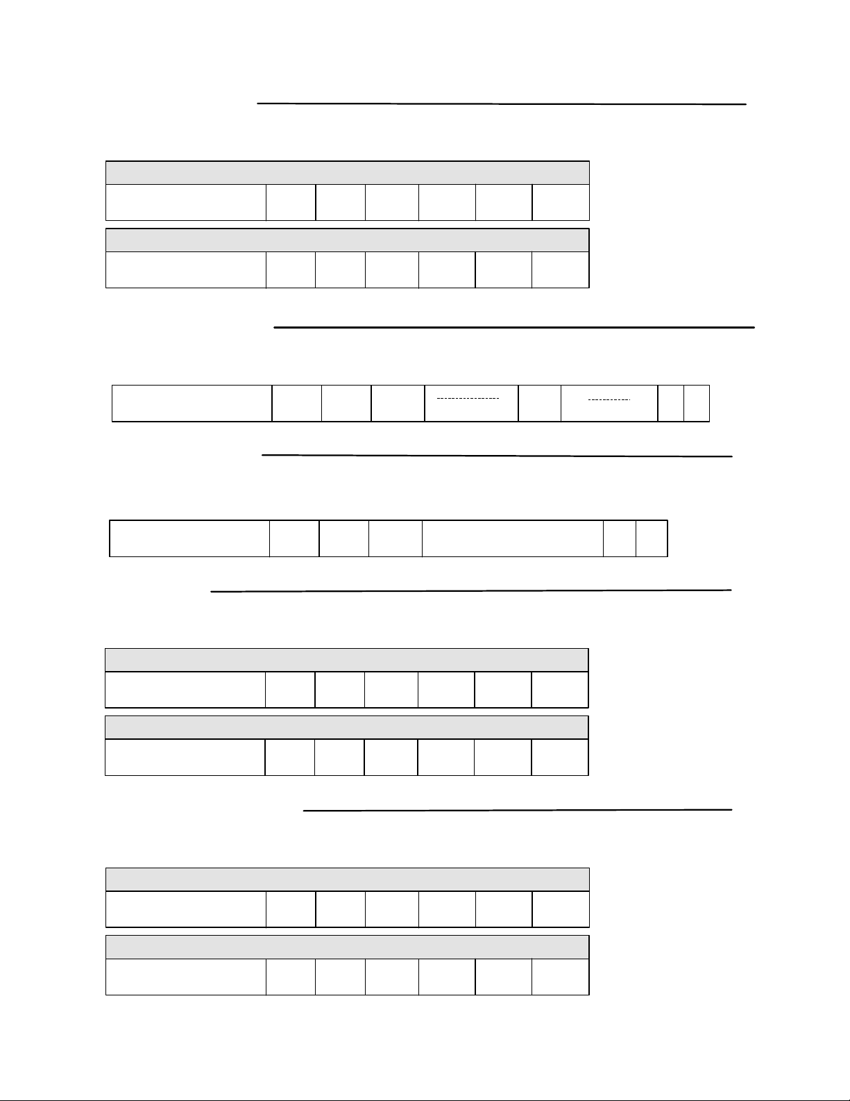
PIN ONLY ENTRY
The PIN only mode will shorten the code required to open the lock.
Enter MASTER CODE
Enter MASTER CODE
ENABLE (PIN TO OPEN LOCK)
#
DISABLE (USER ID & PIN TO OPEN LOCK)
#
32
*
32
*
*
*
0
1
*
*
*
*
CHANGE USER PIN
This function gives the users the ability to change their PIN (user must know their User ID & PIN to perform this function).
Enter MASTER CODE
#
08
*
(New PIN)
*
(Verify PIN)
DEFINE OPEN TIME
This function will adjust the amount of time the lock will stay unlocked after a valid User code has been entered.
The open time can be set from 1 to 9 seconds (default setting is 3 seconds).
Enter MASTER CODE
#
18
*
Single digit 1 – 9 Seconds
*
*
*
*
LOCK AUDIO
When the audio is set to “ON” the lock will beep with each key pressed (ON by default).
AUDIO OFF
Enter MASTER CODE
Enter MASTER CODE
#
#
34
AUDIO ON
34
*
*
0
1
*
*
*
*
TERMINATOR ON/OFF
This function will switch the Terminator On or Off. Selecting off automatically sets lock to PIN Only mode. To gain access with
Terminator Off, simply enter your PIN code. With Terminator On, you are required to enter after your code.
Enter MASTER CODE
Enter MASTER CODE
*
TERMINATOR OFF
#
#
37
TERMINATOR ON
37
*
*
*
0
1
*
*
*
*
NOTE: TO ENTER PROGRAM MODE WITH TERMINATOR OFF, YOU MUST FIRST PRESS THE “#” KEY BEFORE THE MASTER CODE.
P:\INSTALLATION INST\ELECTRIFIED LOCKSETS/INST-E72K-A/INST-E72K-A.vsd REV - 07-08 Page 3
Page 4
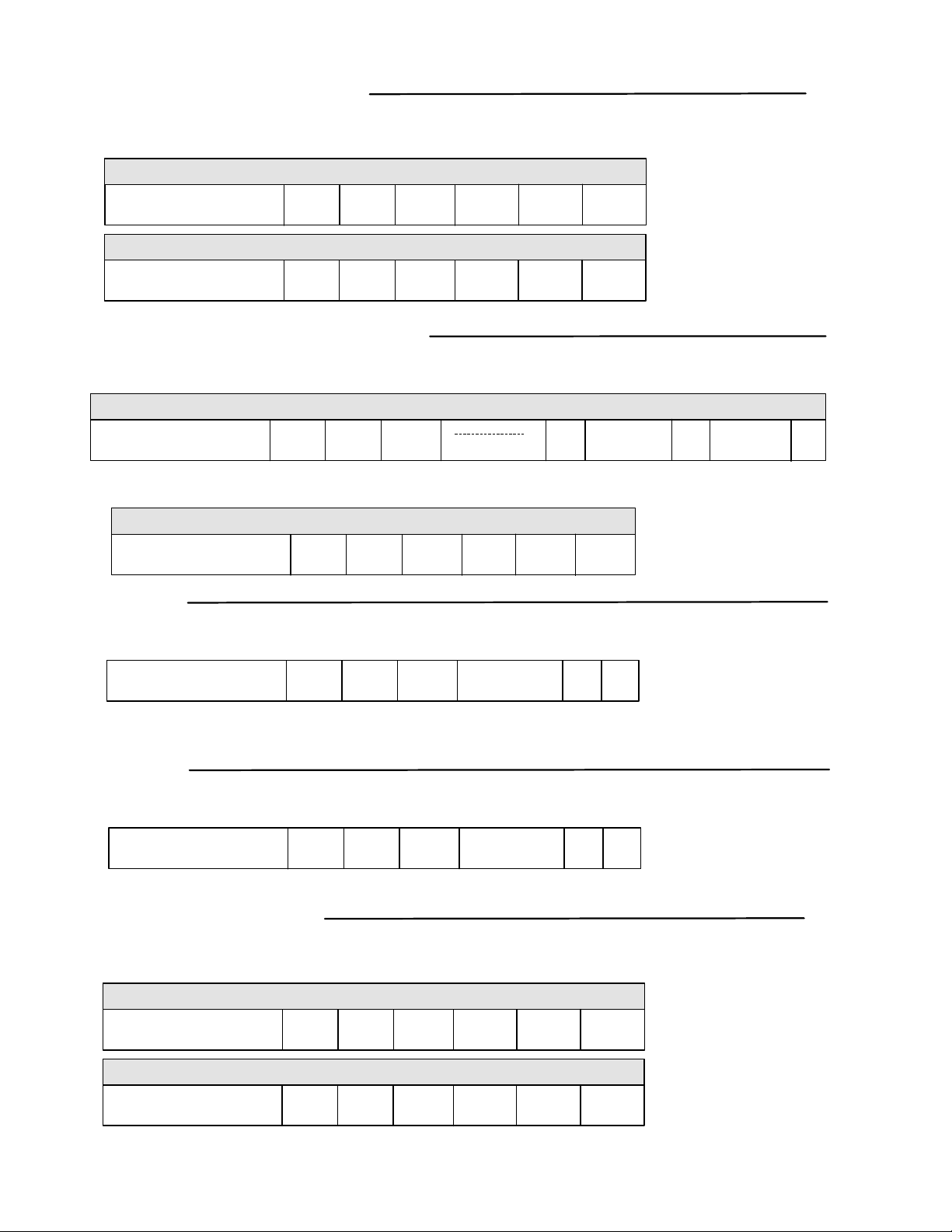
MANUAL PASSAGE MODE
This function puts the lock in an unlocked state, granting free egress (no code required) to all Users until the lock is returned to the
locked state. Returns to locked state at midnight and requires that the time be set (see “Set Time” below).
ENABLE
Enter MASTER CODE
Enter MASTER CODE
#
#
30
DISABLE
30
*
*
1
0
**
**
TEMPORARY USER SCHEDULE
This function allows you to restrict an existing Users’ access by a date range. Temporary User Schedules must be maintained or
access repeats annually. This function requires setting the date in the lockset (see “Set Date” below).
ADD TEMPORARY USER SCHEDULES
*
MMDD
(End Date)
Enter MASTER CODE
“Delete Temporary User schedules” allows you to delete existing Temporary User Schedules. This will delete ALL Temporary
User Schedules.
Enter MASTER CODE
#
DELETE TEMPORARY USER SCHEDULES
06
#
*
06
*
(User ID)
0
*
*
MMDD
(Start Date)
*
SET TIME
This function will set the time (HHMM). Time is set in 24 hour format (example: 3:30pm = 1530).
*
Enter MASTER CODE
Daylight savings time is enabled by default. To disable daylight savings, add a “0” (zero) at the end of the time entry.
(Example: 3:30pm = 15300)
#
12
*
HHMM
*
*
SET DATE
This function will set the Month, Date and Year. There are two formats available: Standard (default MM-DD-YY)
or European (DD-MM-YY).
Enter MASTER CODE
NOTE: FOR EUROPEAN DATE FORMAT SET: DD MM YY “0” (ZERO).
#
13
*
MMDDYY
*
*
DOUBLE CODE ENTRY
For higher security the lock can be set to require that twoUser codes be entered before access is granted.
SINGLE CODE
Enter MASTER CODE
Enter MASTER CODE
#
DOUBLE CODE
#
33
33
*
*
0
1
**
**
P:\INSTALLATION INST\ELECTRIFIED LOCKSETS/INST-E72K-A/INST-E72K-A.vsd REV - 07-08 Page 4
Page 5
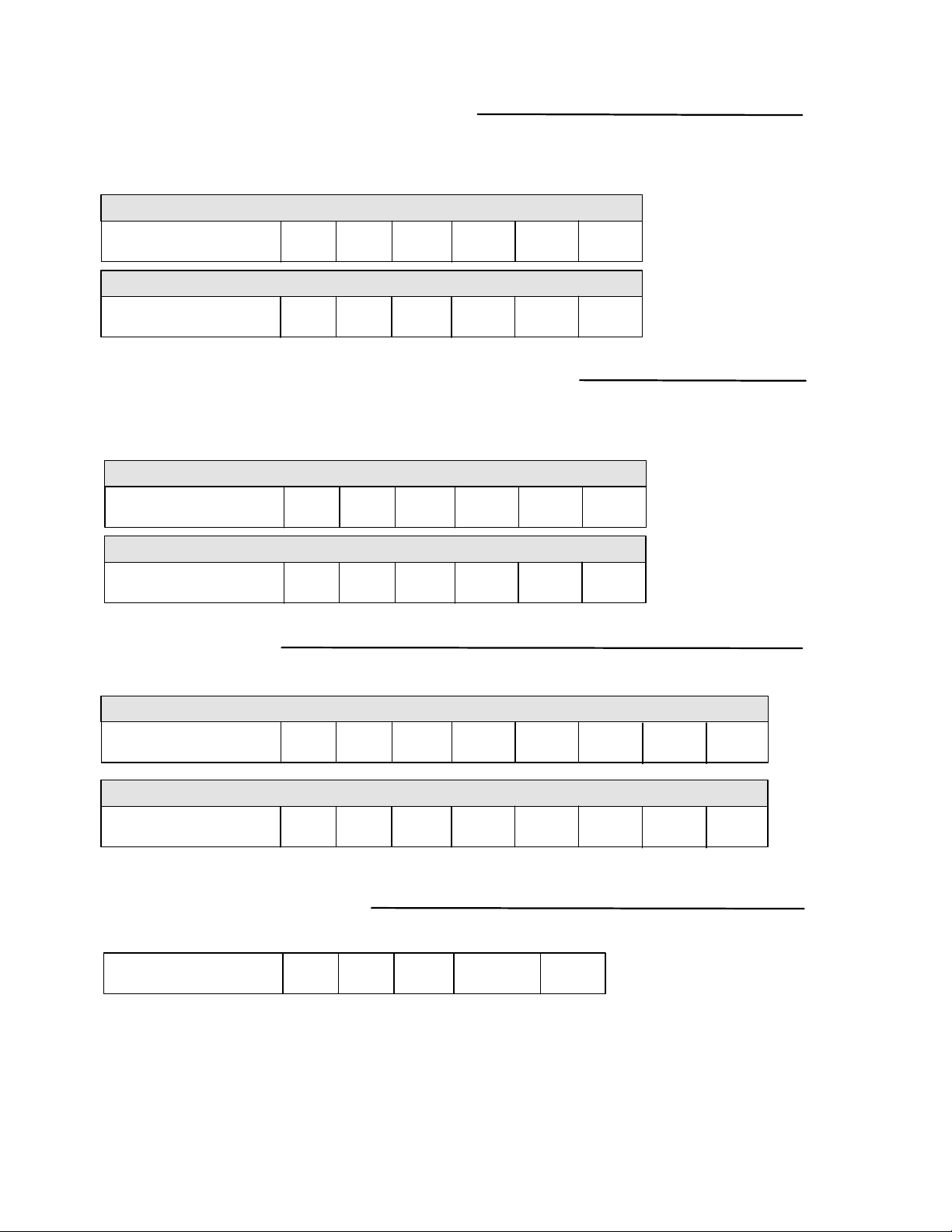
PRIVACY MODE/SECRETARY MODE
An E72K-A with the Privacy Mode option (Secretary Mode is default) will have a button installed on the inside housing. When the button
is pressed it will block out keypad entries (except User Codes from groups 01-03). When the inside lever is pressed the request to exit
switch will reset the keypad back to normal operating mode.
PRIVACY MODE
Enter MASTER CODE
Enter MASTER CODE
#
#
39
SECRETARY MODE
39
*
*
1
0
*
*
*
*
DISABLE/ENABLE THREE STRIKE LOCKOUT
The lock responds to three consecutive incorrect codes by displaying a red light and shutting down the keypad for 20 seconds. Subsequent
attempts with an incorrect code will increase the time to 40 seconds maximum. Disabling this feature allows an unlimited number of
incorrect codes to be entered without a lockout.
DISABLE
Enter MASTER CODE
Enter MASTER CODE
#
#
40
ENABLE
40
*
*
0
1
**
**
CLEAR MEMORY
If it becomes necessary to clear the memory of the E72K-A, there are two options other than the “Full Reset” option.
DELETE ALL USERS AND SCHEDULES
Enter MASTER CODE
Enter MASTER CODE
#
#
16
DELETE ONLY SCHEDULES
16
*
*
16
16
*
*
0
1
**
*
BATTERY CHECK STATUS
This function manually checks the battery status of E72K-A. The LED on the keypad will display visual indicator.
Enter MASTER CODE
Green – Green: Two green LED flashes indicate full power 5.25 volts and above.
Yellow – Yellow:Two yellow LED flashed indicate 5.25 to 4.75 volts.
Yellow – Red: Yellow then red LED flashes indicate 4.75 to 4.37 volts.
Red -Red: Two red flashes indicate below 4.37 volts. Batteries need to be changed.
NOTE: IF THE VOLTAGE OF THE BATTERIES FALLS TO 4.2v DC, THE
E72K-A WILL BEEP EVERY HOUR INDICATING LOW BATTERY STATUS.
P:\INSTALLATION INST\ELECTRIFIED LOCKSETS/INST-E72K-A/INST-E72K-A.vsd REV - 07-08 Page 5
#
17
*
Watch LED
*
*
Page 6
BATTERY INFORMATION
THE E72K-A IS SHIPPED WITH 4 “AA” ALKALINE BATTERIES: The life span has been tested in two different ways. The first test was
performed to see how many operations could be performed repeatedly before a failure. The test averaged 150 thousand operations. The second test was
performed over time for normal operations. This test revealed the the E72K-A batteries would last approximately 4 years at 80 -90 thousand operations.
Using the factory settings, the lockset is set for optimized power usage.
CHANGE THE BATTERIES: The batteries should not be disconnected longer than 10 minutes or there is a risk of affecting the lock’s memory.
IT IS RECOMMENDED TO USE ONLY ALKALINE BATTERIES: The alkaline battery has a gradual curve in the drop off voltage. This curve
determines the power settings for the two stages of battery warnings and the Fail Secure settings. A lithium battery differs from an alkaline battery in the
life cycle of the battery cell. A lithium battery has a very sharp drop off voltage, going from fully charged to a dead cell quickly. This make monitoring
the voltage settings impossible.
TWO STAGE LOW BATTERY WARNING: The E72K-A has a two stage low battery warning. The First warning stage will add a double beep and
Red LED when the user enters their code. The second warning stage will be a double beep every hour. BATTERIES SHOULD BE CHANGED
IMMEDIATELY. Double beeps will occur until the batteries fail.
BATTERY INFORMATION
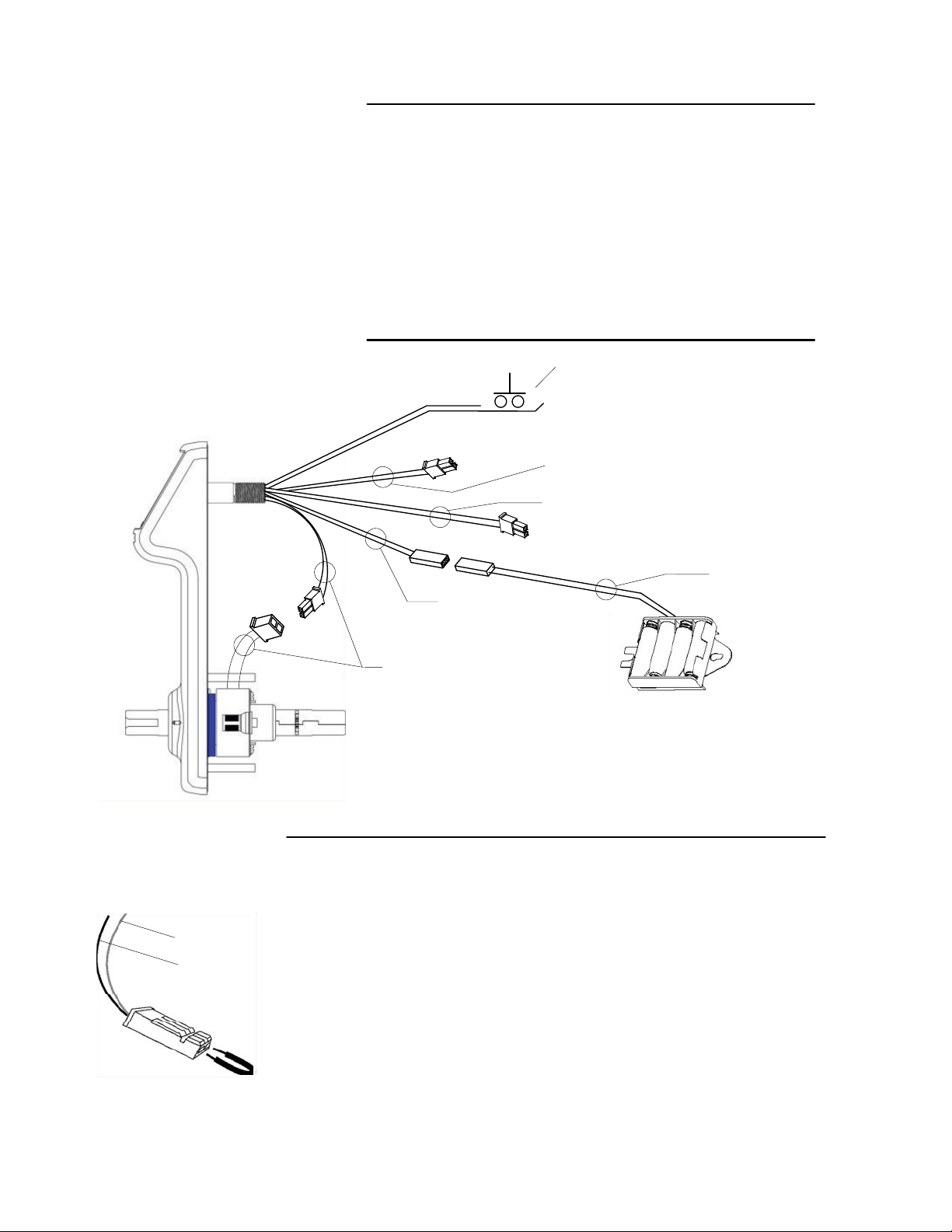
Secretary’s Button: Orange & Black
This can be wired to a Momentary Normally Open
(NO) switch. When pressed, lock will open for the set
amount of time (button not included).
Blue & Black
Request to Exit Switch (Factory Installed option)
Reset/Key Switch black & Yellow (Factory Installed option)
This option will monitor if a key is used to open a lock. For
resetting the E72K-A, see below.
RESET THE LOCK
Yellow
Black
Red & Black
Power RED (+) & Black (-)
6 Volts DC Connects to the
supplied battery pack
Motor Cable
Red & Grey lines to the
motor connector
1. Open battery cover (top of housing on inside of door).
2. Unplug the batteries.
3. Locate the Yellow and Black cable (behind battery pack).
4. Insert both ends of the reset wire (or metal paper clip) into the holes of the connector on
the yellow and black cable.
5. With the reset wire in place, reconnect the batteries (the LED will go RED then GREEN;
and you will hear the lock relock).
6. Remove the reset wire and replace the battery holder and cover onto the housing.
The lock is now reset. Now create the new Master Code (see page 2).
P:\INSTALLATION INST\ELECTRIFIED LOCKSETS/INST-E72K-A/INST-E72K-A.vsd REV - 07-08 Page 6
Page 7
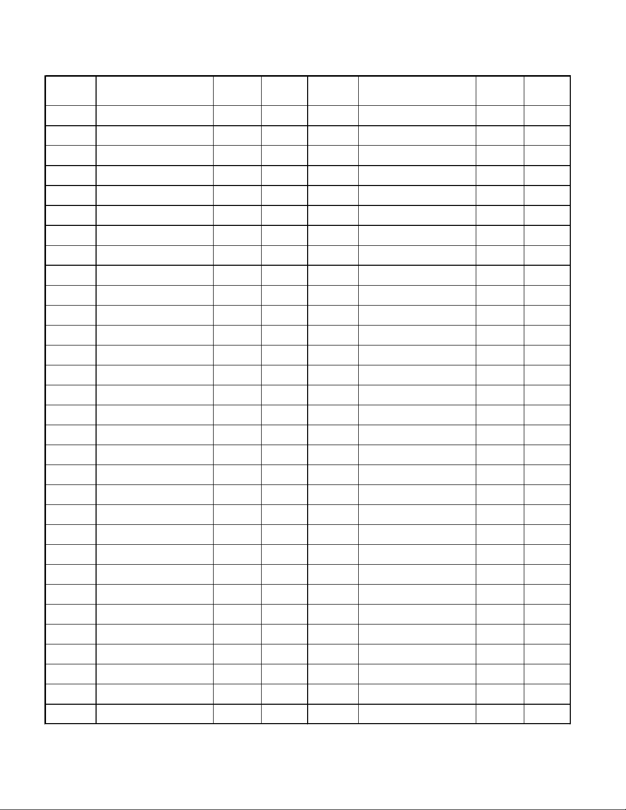
User
Number
Name
Group
Number
PIN
Code
User
Number
Name
Group
Number
PIN
Code
P:\INSTALLATION INST\ELECTRIFIED LOCKSETS/INST-E72K-A/INST-E72K-A.vsd REV - 07-08 Page 7
 Loading...