

Page 1
801 Avenida Acaso, Camarillo, Ca. 93012
(805) 494-0622 • Fax: (805) 494-8861
www.sdcsecurity.com • E-mail: [email protected]
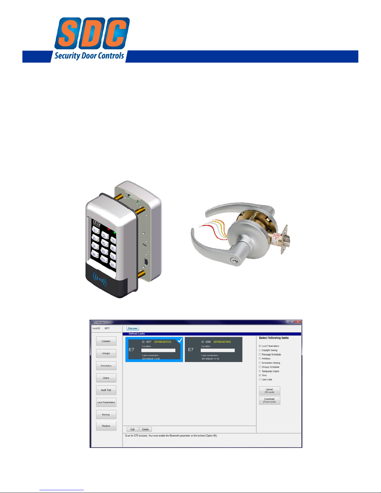
E70PS Series
PC Managed Electronic Lockset
E7 Software Installation & Operations Manual
P:\INSTALLATION INST\ACCESS CONTROLS\E75\INST-E7 SW Install Manual.vsd 10-14 Page Cover
Any suggestions or comments to this instruction or
product are welcome. Please contact us through
our website or email [email protected]
Page 2

1.0 Introduction
1.1 PC Requirements
Table of Contents
1
2.0 E7 Manager Software Installation
3.0 Before You Start
3.1 LED Indicators
3.2 Testing the Lock Operation
3.3 Lock Initialization
3.4 Entering/Exiting Programming Mode
3.5 Enabling Bluetooth Communications Mode (Function 80)
3.6 Changing the Administrator PIN Code
4.0 Getting Started
4.1 E7 Manager Layout & Features
4.2 Discovering a New Lock
4.3 Setting the Date & Time
4.4 Quick Start User Programming
5.0 E7 Manager Programming
5.1 Schedules
5.1.1 Group Schedules
5.1.2 Passage Schedules
5.1.3 Adding Holidays
5.1.4 Daylight Savings Time
5.2 Groups
5.3 Users
5.3.1 Add/Edit User Access
5.3.2 Copy Users from an Existing Lock
5.3.3 Export User Data to a File
5.3.4 Import User Data from a File
5.3.5 Temporary Users
5.4 Audit Trail
5.4.1 Download Events from a Lock
5.4.2 Export Events to a File
5.5 Lock Parameters
Entry Mode
Set Open/Unlock Time
Enable First Supervisor to Arrive
Delete Temporary Users When Expired
Enable Two User Codes Required
Set Keypad Lockout Attempts
Enable Audible Beep on Key Press
Enable Anti-Passback Mode
Enable Remote Input Mode
Enable Door Position Switch (DPS) Input
DPS Input Configuration
Enable Auxiliary Relay (Forced Door, Door Prop, Keypad Lockout, Access Grant)
Enable Holdup Alarm
5.6 Backup & Restore
5.6.1 Create a Database Backup
5.6.2 Restore a Database from a F
ile
1-2
3
3
3
3
4
4
5
6
7
7-8
9
9
10
10
10
11
11
11
11
12
12
12
13
14
14
P:\INSTALLATION INST\ACCESS CONTROLS\E75\INST-E7 SW Install Manual.vsd 10-14 Page i
Page 3
1.0 Introduction
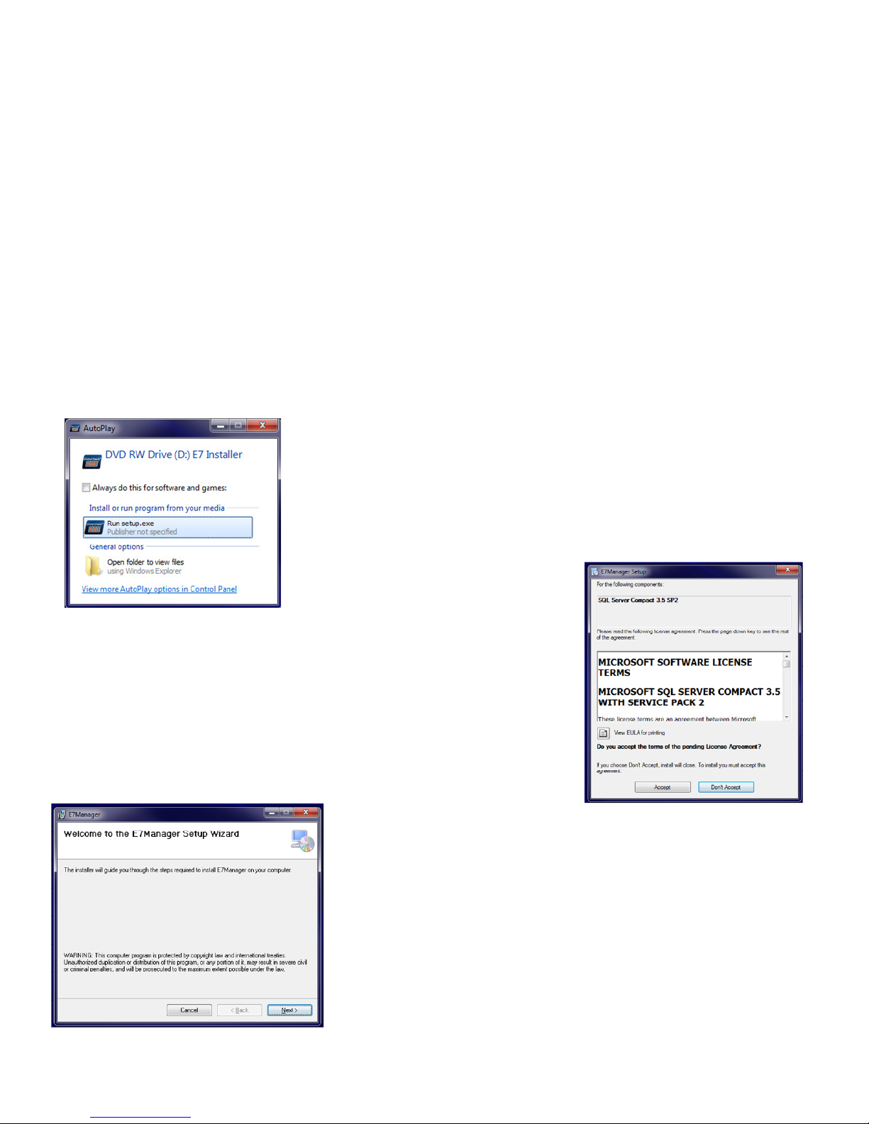
The E70PS Series incorporates SDC’s battery powered, motorized Grade 1 lock with the E7 Lock Management
Software. The software allows administrators to easily manage multiple locks & users from a single database.
Authorized Users, schedules and lock configurations are uploaded from a Bluetooth-enabled PC. Audit trail
information may be downloaded and exported as a comma-delimited file.
1.1 PC Requirements
• Supported Operating Systems: Windows XP Service Pack 3, Windows 7, Windows 8 (32-Bit and 64-Bit Systems)
• Processor: 2GHz or faster is recommended
• RAM: 2GB or more is recommended
• Hard Disk Space: 1GB or more is recommended
• Windows Administrative Rights
2.0 E7 Manager Software Installation
Insert the E7 Manager Installation CD into your computer CD/DVD drive.
From the AutoPlay window, select Run setup.exe
If AutoPlay is not enabled on your computer, use Windows Explorer to access
your CD/DVD drive. From Windows Explorer, right-click on setup.exe and
select “Run as Administrator”.
The E7 Manager database utilizes Microsoft SQL Server Compact 3.5 SP2. This
window will appear if it is not already installed on your PC.
You must accept the agreement to continue the installation.
After accepting the agreement, the E7 Manager Setup Wizard
window will appear.
Select “Next”.
P:\INSTALLATION INST\ACCESS CONTROLS\E75\INST-E7 SW Install Manual.vsd 10-14 Page 1
Page 4
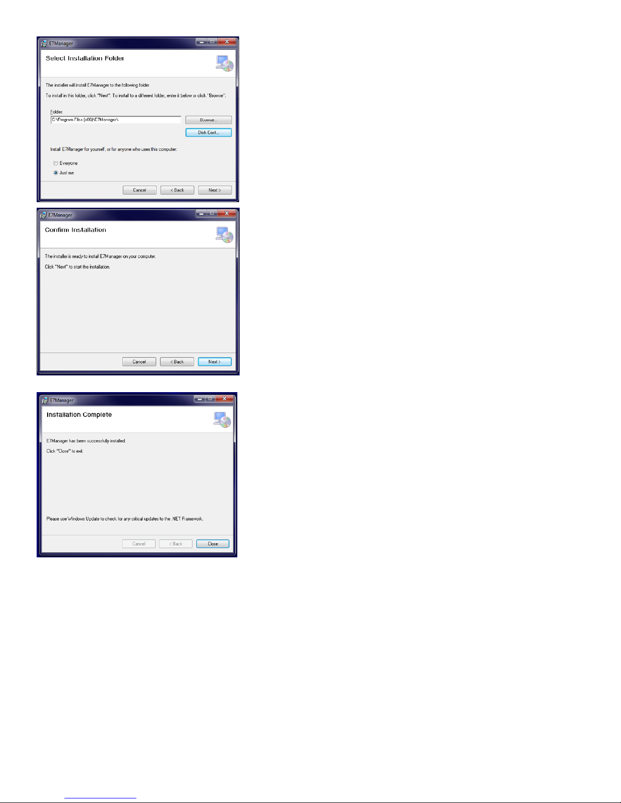
Select the Installation Folder. The default folder is recommended.
If multiple accounts log in the same computer, select whether the
program will be available to one or all users.
Select “Next”.
Select “Next” to confirm the installation.
Select “Close” to complete the installation. Please use Windows
Update to check for any critical updates to the .NET Framework.
P:\INSTALLATION INST\ACCESS CONTROLS\E75\INST-E7 SW Install Manual.vsd 10-14 Page 2
Page 5

3.0 Before You Start
3.1 LED & Audible Indicators
There are 2 LED indicators on the front face of the lock. The leftmost LED may illuminate RED, GREEN, or YELLOW.
The right LED will only illuminate BLUE.
From Normal Operational (Standby) Mode,
Both LEDs OFF
Momentary GREEN
Momentary RED
From Programming Mode,
= Standby Mode, or Keypad Lockout
= After each key press, or Access Granted
= Error
Flashing YELLOW
Flashing BLUE
GRN LED+Beep (Simultaneous)
Both LEDs OFF
GRN LED+Beep (x2)
GRN LED+Beep, RED LED+Beep, GRN LED+Beep
YEL LED+Beep, Pause, GRN LED+Beep (x3) = Exiting Program Mode
Alternating RED/GRN LED, then 3 Beeps
= In Programming Mode
= Bluetooth Enabled
= While performing any Function, an intermediate step has been accepted
= While performing any Function, waiting for user input
= Function Successfully Completed
= Entering Program Mode
= On Lock Power Up
3.2 Testing the Lock Operation
To test lock operation before initialization, enter *741. This temporary code will unlock the E75 for verifying proper
hardware installation. NOTE: The lock will unlock, but the Green LED will not light.
Once a lock initialization has been performed, this code is no longer valid until a factory reset is performed. A factory
reset will erase all the users, lock settings, and return the E75 back into the uninitialized factory default condition.
3.3 Lock Initialization
When the lock is first installed or after a factory reset has been performed, the E75 must be initialized with a 4-digit
lock ID before you will be allowed to enter programming mode. This step is required before using the E7
Management Software.
To Initialize the Lock: Press #9*123456#4-digit Lock ID#
Example: Press #9* 123456# 0001#
The above example enters a Lock ID of ‘0001’. If multiple locks are used, it is mandatory that each lock have its
own Unique Lock ID (0002, 0003, etc.).
3.4 Entering and Exiting Programming Mode
The E7 Management Software utilizes Bluetooth communications to transfer data to & from a lock. You must first put
the lock into Programming Mode to enable Bluetooth. NOTE: While in Programming Mode, the leftmost LED will flash
yellow (once/sec). Twenty seconds of inactivity will automatically exit you from programming mode and return you to
operational (standby) mode.
To Enter Programming Mode:
Example: Press #9# 01# 123456#
User 01 with default PIN Code 123456 is the Administrator and has full programming rights. It is recommended that this PIN
Code be changed, as instructed in 3.6. NOTE: The User must be the Administrator or must be assigned to Groups 2-5 to have
programming rights.
To Exit Programming Mode: Press **#
Example: Press **#
P:\INSTALLATION INST\ACCESS CONTROLS\E75\INST-E7 SW Install Manual.vsd 10-14 Page 3
Press #9# User No# User PIN Code #
Page 6

3.5 Enabling Bluetooth Communications Mode (Function 80)
You must enable Bluetooth Communications using the lock keypad before data can be transmitted to & from the lock.
NOTE: You must first be in Programming Mode to enable Bluetooth (Section 3.4). The lock will automatically exit
Bluetooth Mode after 2 minutes of upload/download inactivity.
To Enable Bluetooth Mode: Press 80#
Bluetooth communication is now enabled. T
he rightmost LED will flash BLUE (once/sec).
To Disable Bluetooth Mode: Press
Bluetooth communication is now disabled. T
*
he left LED will flash YEL to indicate the lock is in Programming Mode.
3.6 Changing the Administrator PIN Code
User 01 is the Administrator with full programming rights. The default PIN Code is ‘123456’. Changing the
Administrator’s PIN code must be done manually at the keypad.
NOTE: The Administrator’s PIN code must be 6 digits in length.
To Change the Administrator PIN Code: Press 03# 01# New PIN Code# New Pin Code#
Example: Press 03# 01# 987654# 987654#
You have just changed the Administrator Pin Code to ‘987654’.
P:\INSTALLATION INST\ACCESS CONTROLS\E75\INST-E7 SW Install Manual.vsd 10-14 Page 4
Page 7
4.0 Getting Started
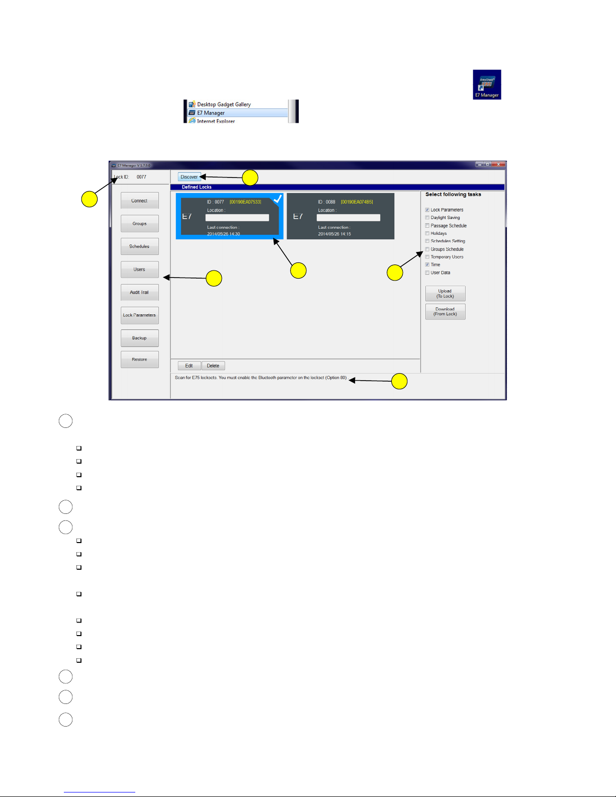
4.1 E7 Manager Layout & Features
Start the E7 Manager program by clicking on the E7 Manager Shortcut created on the Desktop
or in the Windows Start Menu
The program will automatically open to the ‘Connect’ screen:
2
6
3
1
Defined Locks Window – All locks that have been discovered by the software will appear here. The currenlty
1
4
5
selected lock is checked & highlighted in Blue. Each lock is identified with a:
Lock ID – This is the ID set during lock initialization (Section 3.3)
Hardware ID – Bracketed, yellow text
Location – Blank by default.
Last successful connection date & time
Discover Button – Used to add new locks into the database (Section 4.2)
2
Menu Navigation Buttons – Used to navigate between the available software menus:
3
Connect – Main startup screen. Add or delete locks. Upload and Download multiple task items.
Groups – Create User Groups (up to 32). Assign Schedule(s) to User Groups.
Schedules – Create Group Access Schedules (up to 32), Passage Schedules, Holidays, & enable Daylight
Savings Time.
Users – Add/Edit/Delete User PIN numbers and/or Card numbers (up to 3,000). Assign or change a Group
# to a user.
Audit Trail – Download transactions from the lock (up to 10,000 events). Export audit trail to a file.
Lock Parameters – Refer to Table of Contents (Section 5.5) for a list of parameters
Backup – Create a copy of the database on a local directory
Restore – Restore a saved copy of the database from a local directory
Upload/Download Tasks – Used to upload/download multiple database categories to/from the selected lock.
4
5
Message Box – Placing the mouse pointer over a button will display help information in this box.
6
Lock ID – The 4-digit Lock ID of the currently selected lock. Always verify that the desired lock is selected
before editing any lock parameters.
P:\INSTALLATION INST\ACCESS CONTROLS\E75\INST-E7 SW Install Manual.vsd 10-14 Page 5
Page 8
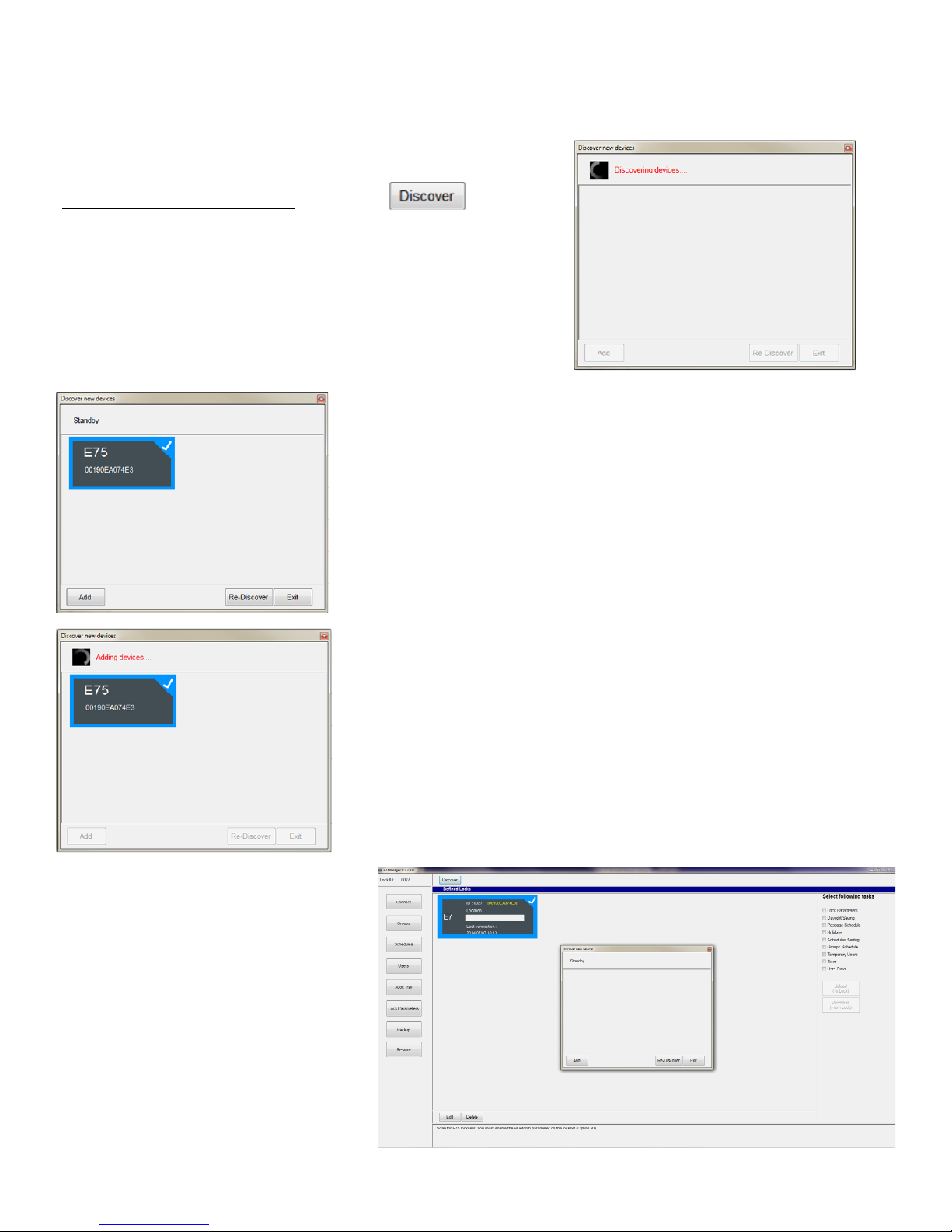
4.2 Discovering a New Lock
To add a new lock, you must first put the lock into Programming Mode, and then enable Bluetooth Mode. Refer to
Sections 3.4 & 3.5.
Navigate to the ‘Connect’ screen (default on startup)
While Bluetooth Mode is enabled, click on the button.
E7 Manager will attempt to discover anyBluetooth enabled device(s)
within range.
The discovered lock(s) will appear in the window. Select the desired lock(s)
to be added to E7 Manager. Selected locks will have a blue highlighted
border and checkmark.
If only one lock is discovered, it will automatically be selected.
If desired, update the lock Location by
selecting a lock and clicking ‘Edit’.
Type the new location name in the blank
field below ‘Location:’, and click ‘Save’.
Click the ‘Add’ button.
After a lock is successfully added, it will appear in the Defined Locks window.
Click ‘Exit’ to close the ‘Discover new devices’ window.
P:\INSTALLATION INST\ACCESS CONTROLS\E75\INST-E7 SW Install Manual.vsd 10-14 Page 6
Page 9
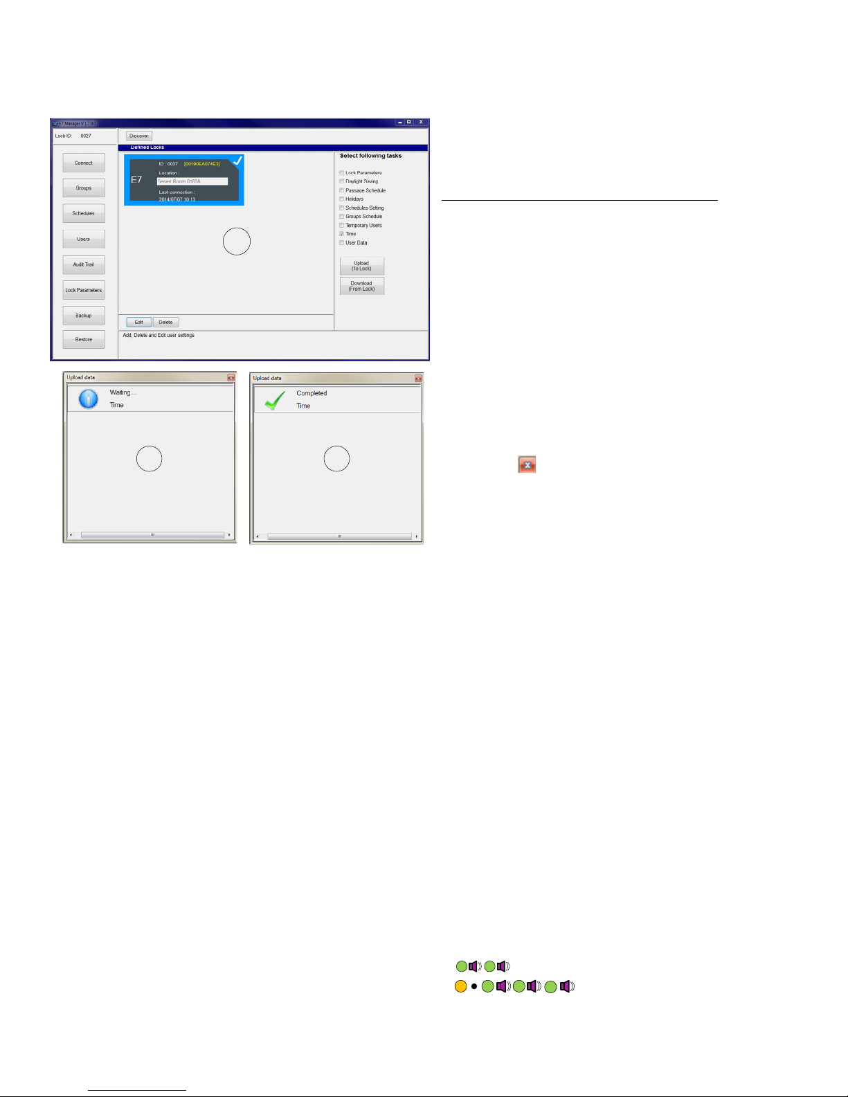
4.3 Setting the Date & Time
Setting the correct date and time is essential for proper operation of access schedules, and to maintain an accurate
audit trail.
From the ‘Connect’ screen, check the box next to the
‘Time’ task on the right.
While Bluetooth Mode is enabled at the lock, click on
the ‘Upload (To Lock)’ button.
1
The Upload data message window will appear.
The ‘Waiting…’ message will change to ‘Completed’
when the time has been successfully uploaded.
2 3
Click on the to close the window.
4.4 Quick Start User Programming
Below are step-by-step procedures for two typical programming scenarios. It assumes that the lock has been
initialized with a Lock ID and that the steps in Sections 4.2 & 4.3 have been completed.
Refer to Section 5 for additional programming options.
Typical Programming Example #1:
All users will be assigned to Group 06 (24/7 Access by default).
Keypad PIN OR Prox Card may be used to gain access.
Unlock Time = 3 seconds (default).
Step 1 – Navigate to the Users screen by clicking on the ‘Users’ button.
Step 2 – Verify that both the ‘Valid’ & ‘Enabled’ boxes are checked for each authorized user.
Step 3 – Verify that the Group field is set to ‘6’.
Step 4 – Enter a 4 to 6-digit PIN in the ‘Password’ field. If only Prox Cards are used, skip to Step 5.
Step 5 – Enter a valid card credential. This field consists of the 3-digit card facility code + 5-digit card number.
Leading zeros are not required for the facility code. If only PIN numbers are used, skip to Step 6.
Step 6 – When all users have been entered, click the ‘Save’ button (lower right).
Step 7 – At the lock, enable Bluetooth Mode (Section 3.5).
Step 8 – Click ‘Upload (to Lock)’.A window will appear while user data is being uploaded to the lock. The
upload process may take up to 60 seconds.
Step 9 – At the lock, exit Bluetooth mode by pressing ,
then exit progamming mode by pressing
Test the new users by entering a valid PIN code followed by ‘#’, OR by presenting a valid card to the reader.
P:\INSTALLATION INST\ACCESS CONTROLS\E75\INST-E7 SW Install Manual.vsd 10-14 Page 7
*
*
*
#
Page 10

Typical Programming Example #2:
Normal Users will be have access to the lock during normal business hours (M-F, 07:30 – 17:00).
System Managers will have 24/7 access, including Holidays.
Normal Users will not have programming rights.
System Managers will have full programming rights.
Keypad PIN OR Prox Card may be used to gain access.
Unlock Time = 3 seconds (default).
Step 1 – Navigate to the Schedules screen by clicking on the ‘Schedules’ button.
Step 2 – Create a System Manager schedule (choose Schedule #2, for example). Select all the Days of the
Week. Set the Start Time to 0 : 0. Set the End Time to be 23:59. Check Override Holidays.
Step 3 – Create a Normal User schedule (choose Schedule #10, for example). Select Monday - Friday. Set the
Start Time to 07:30. Set the End Time to be 17: 0. Click Save (lower right).
Step 4 – Navigate to the Groups screen by clicking on the ‘Groups’ button.
Step 5 – Create a System Manager group. Under Group #2, check ‘Schedule No. 1’. Using the drop-down
menu, select ‘Schedule #2 00:00 23:59’.
Step 6 – Create a Normal User group. Under Group #10, check ‘Schedule No. 1’. Using the drop-down
menu, select ‘Schedule #10 07:30 17:00’. Click Save.
Step 7 – Navigate to the Users screen by clicking on the ‘Users’ button.
Step 8 – Verify that both the ‘Valid’ & ‘Enabled’ boxes are checked for each authorized user.
Step 9 – Verify that the Group field is set to ‘2’ for System Managers. Verify that the Group field is set to ‘10’
for Normal Users.
Step 10 – Enter a 4 to 6-digit PIN in the ‘Password’ field. If only Prox Cards are used, skip to Step 11.
Step 11 – Enter a valid card credential. This field consists of the 3-digit card facility code + 5-digit card number.
Leading zeros are not required for the facility code. If only PIN numbers are used, skip to Step 12.
Step 12 – When all users have been entered, click the ‘Save’ button.
Step 13 – Navigate to the Connect screen. Under Select following tasks, check Schedules Setting, Groups
Schedule, and User Data.
Step 14 – At the lock, enable Bluetooth Mode (Section 3.5). From the Connect screen, click ‘Upload (To Lock)’.
A window will appear while data is being uploaded to the lock. The upload process may take up to 90
seconds.
Step 15 – At the lock, exit Bluetooth mode by pressing ,
then exit progamming mode by pressing
Test the new users by entering a valid PIN code followed by ‘#’, OR by presenting a valid card to the reader.
P:\INSTALLATION INST\ACCESS CONTROLS\E75\INST-E7 SW Install Manual.vsd 10-14 Page 8
*
*
*
#
Page 11
5.0 E7 Manager Programming
As a general rule, there are four basic steps to adding new users to the E7 Management Software:
1. Create user group schedules (Section 5.1.1)
2. Create user groups (Section 5.2)
3. Assign user groups to individual users (Section 5.3.1)
4. Upload changes to the lock
Sections 5.4, 5.5, & 5.6 cover advanced programming functions.
5.1 Schedules
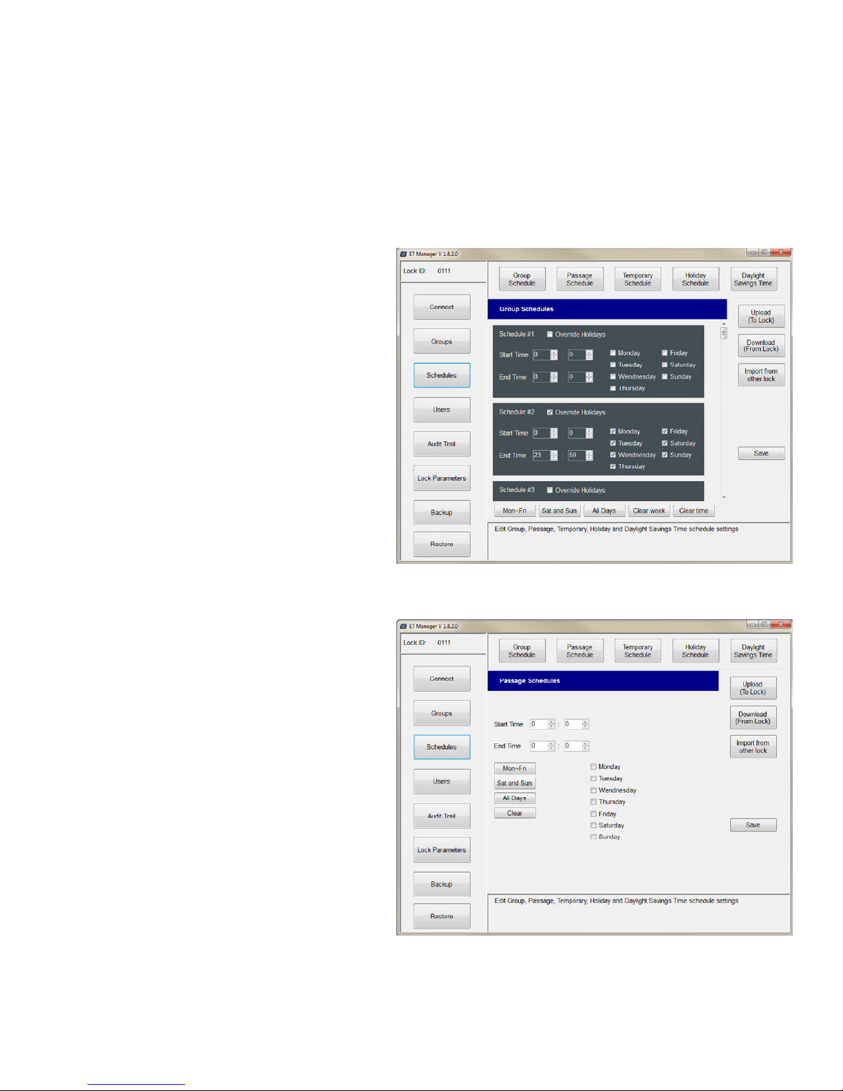
5.1.1 Group Schedules
There are 32 possible group schedules. Choose a
schedule to edit.
Set the Start Time & End Time in a 24HR format (For
example, 16:30 = 4:30pm).
Check the Days when the schedule will be active.
Check ‘Override Holidays’ if required. Selecting this
option will allow assigned users to have access on
days designated as Holidays.
Click Save.
Enable Bluetooth communications at the lock and
select ‘Upload (To Lock)’
5.1.2 Passage Schedules
A passage schedule will unlock the lock for an
extended period of time (e.g., during normal business
hours.)
Notes:
1. Only one passage schedule time period is allowed
per lock
2. Passage schedules will not be active on Holidays
Set the Start Time & End Time in a 24HR format (For
example, 16:30 = 4:30pm).
Check the Days when the passage schedule will be
active.
Click Save.
Enable Bluetooth communications at the lock and
select ‘Upload (To Lock)’
P:\INSTALLATION INST\ACCESS CONTROLS\E75\INST-E7 SW Install Manual.vsd 10-14 Page 9
Page 12
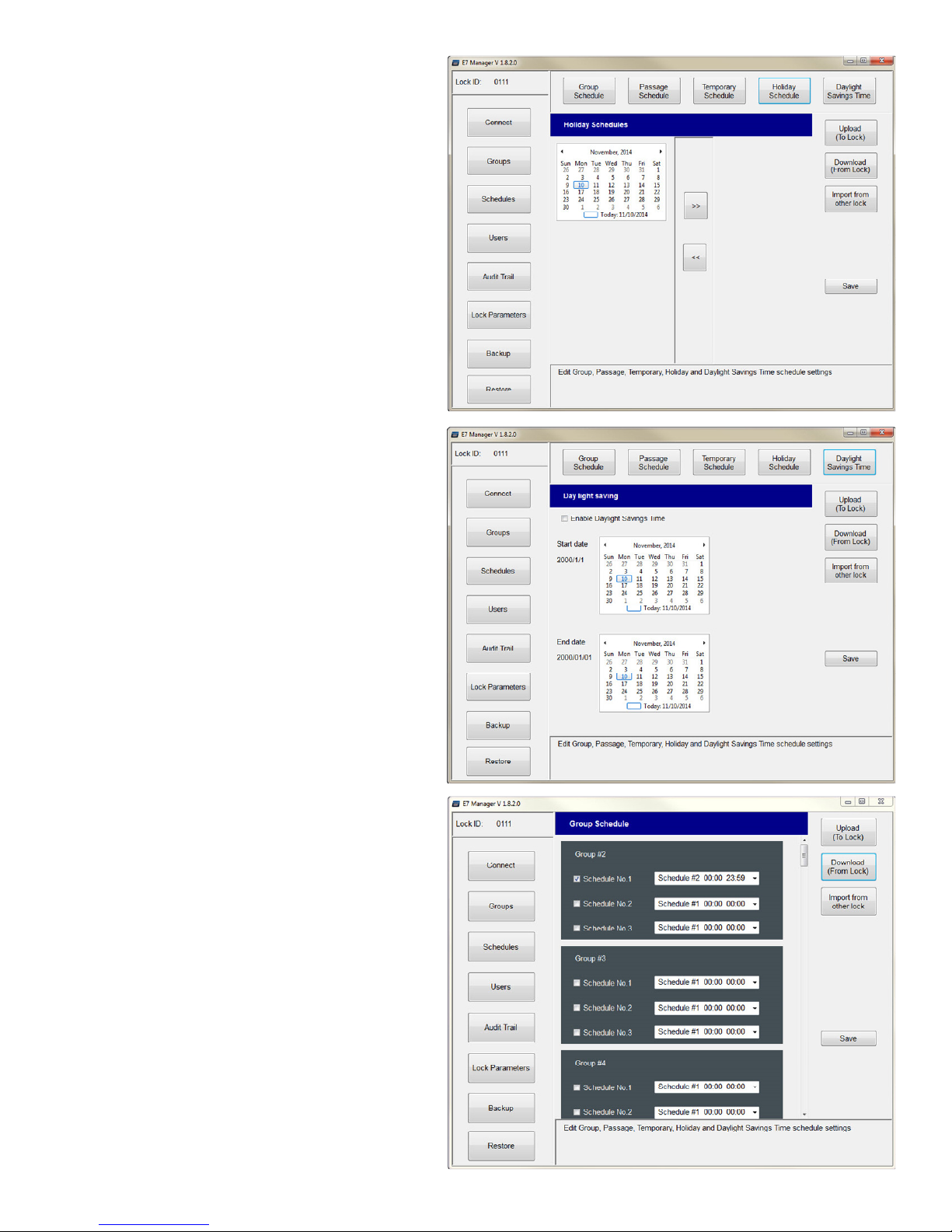
5.1.3 Adding Holidays
Up to 32 separate Holidays may be programmed.
NOTE: Users that are not assigned to a schedule that
can ‘Override Holidays’ will be denied access on
Holidays.
Using the calendar, click to highlight the day you
desire to configure as a holiday.
Click on the ‘>>’ button. The selected date will appear
on the right as a holiday.
Add additional days as required, and click Save.
Enable Bluetooth communications at the lock and
select ‘Upload (To Lock)’
5.1.4 Daylight Savings Time
Using the calendars,
Set the DST Start Date & End Date. You will see the
corresponding date change under the “Start date” &
“End date” text.
Once the dates are set, check the ‘Enable Daylight
Savings Time’ box.
Click Save. Enable Bluetooth communications at the
lock and select ‘Upload (To Lock)’
NOTE: The DST Start & End Dates need to be set
annually.
5.2 Groups
There are 32 available Groups. Choose a Group to edit.
NOTES:
1. User Group #1 is reserved for the Administrator.
2. User Groups #2-5 will have programming rights.
3. All other User Groups do not have programming
rights.
Check the box next to the schedule you want to apply
(Schedule No. 1, 2, and/or 3). You may apply up to 3
schedules per Group.
Using the drop-down menu, select the desired
schedule. Schedules are defined in Section 5.1.1.
Click Save. Enable Bluetooth communications at the
lock and select ‘Upload (To Lock)’
P:\INSTALLATION INST\ACCESS CONTROLS\E75\INST-E7 SW Install Manual.vsd 10-14 Page 10
Page 13
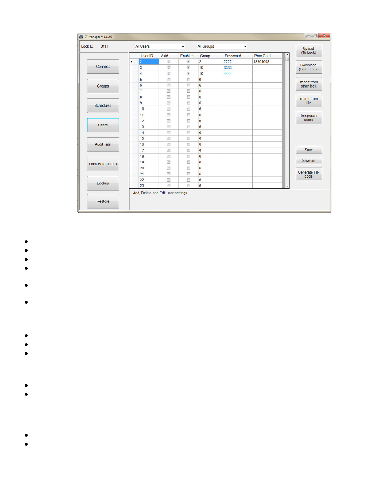
5.3 Users
5.3.1 Add/Edit User Access
There are 3000 users available. User ID ‘1’ is reserved for the Administrator. To add an access user,
Check the ‘Valid’ box next to the user you want to add. Unchecking this box will delete user.
Check the ‘Enabled’ box to enable the user. Unchecking this box will disable the user, but not delete them.
Enter the Group # assigned to the User. Reference Section 5.2.
Under ‘Password’, enter an access PIN #. The PIN must be 4 to 6 digits long. Skip this step if only prox cards are
used.
Under ‘Prox Card’, enter a valid card credential. This field consists of the 3-digit card facility code + 5-digit card
number. Leading zeros are not required for the facility code.
Click Save. Enable Bluetooth communications at the lock and select ‘Upload (To Lock)’
5.3.2 Copy Users from an Existing Lock
You may copy User Data from a lock that is already existing in the database. To copy the user data,
Click the ‘Import from other lock’ button. A separate window will appear listing all the existing locks.
Select the lock whose User data you wish to copy by clicking the box.
Click ‘Import’. A message will appear confirming that the data has been successfully imported. Click Save.
5.3.3 Export User Data to a File
The User database may be exported as a *.csv file, viewable & editable in Microsoft Excel®. To export the user data,
Click the ‘Save as’ button. A ‘Save as’ window will appear.
Select a file location and name. Click Save.
5.3.4 Import User Data from a File
The User database may be imported from a previously exported *.csv file. NOTE: This will override any existing user
data. To import the user data file,
Click the ‘Import from file’ button.
Select a .csv file to be imported. Click Open.
P:\INSTALLATION INST\ACCESS CONTROLS\E75\INST-E7 SW Install Manual.vsd 10-14 Page 11
Page 14
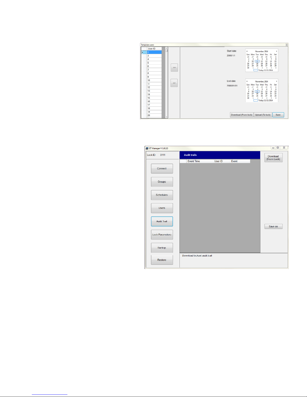
5.3.5 Temporary Users
From the Users menu, click the ‘Temporary users’ button. The Temporary users window will appear.
Select a User ID from the left.
Click on the ‘>>’ button. The user # will appear on
the right.
Select the user by clicking anywhere within the dark
gray box. The box will be highlighted with a blue
border and checkmark.
Adjust the Start & End dates as required. Click Save.
Close the window. From the Users screen, follow
the procedure outlined in Section 5.3.1.
5.4 Audit Trail
5.4.1 Download Events from a Lock
The lock will retain the previous 10,000 normal
access or alarm events.
Click on the ‘Audit Trail’ menu button.
Enable Bluetooth communications at the lock and
select ‘Download (From Lock)’.
NOTE: Navigating away from the Audit Trail screen
will clear the Audit Trail information, and it will be
need to be downloaded again.
5.4.2 Export Events to a File
Downloaded events may be exported as a *.csv file,
viewable in Microsoft Excel®.
Click the ‘Save as’ button. A ‘Save as’ window will
appear.
Select a file location and name. Click Save.
P:\INSTALLATION INST\ACCESS CONTROLS\E75\INST-E7 SW Install Manual.vsd 10-14 Page 12
Page 15
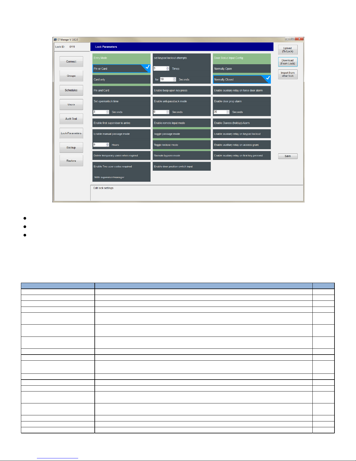
5.5 Lock Parameters
Check to enable. Group and passage schedules are delayed until a user assigned to Groups 2-5 has accessed the lock
Disabled
are disabled, but not deleted.
checked, one of the two user codes must belong to Groups 2-5.
time (10-255 seconds).
Check to enable. An audible beep is heard after every key press.
Enabled
Check to enable. Sets the time before a PIN or Card can be used again after a authorized access (0-100 secs)
Disabled
put into one of three modes: Toggle passage mode, toggle lockout mode, momentary bypass mode.
Check to enable. Enable to monitor forced door or door prop conditions.
Disabled
When the DPS input is enabled, this sets the contact configuration (N/O or N/C)
N/C
Check to enable the aux relay output on a forced door. Latches until a valid card or PIN is presented
Disabled
(10-255 seconds). Latches until the door closes.
holdup alarm. Relay activates for 2 seconds.
Check to enable.
Disabled
Check to enable.
Disabled
Check to enable.
Disabled
The Lock Parameters window allows the user to:
Select ‘Upload (To Lock)’ to upload lock parameter changes to a lock, or
Select ‘Download (From Lock)’ to view/edit an existing lock’s parameters, or
Select ‘Import from other lock’ to copy settings from another existing lock.
Enable Bluetooth communications at the lock, and Download the existing lock parameters.
Edit the Lock Parameters as required and Click Save. Enable Bluetooth communications at the lock and upload the
changes to the lock.
Parameter Description Default
Entry Mode Sele cts the lock entry mode. Check 'Pin or Card', 'Card only', or 'Pin and Card' Pin or Card
Set open/unlock time Sets the normal unlock time. 3 Sec
Enable first supervisor to arrive
Enable manual passage mode This option is disabled
Check to enable. Temporary users will be deleted after ex piration when enabled. When disabled, temporary users
Delete temporary users when expired
Check to enable. Two user codes are required to access the lock. Additionally, if 'With supervisor/manager' is
Enable Two user codes required
Sets the number of invalid keypad attempts before the keypad is locked out (1-9 attempts). Sets the keypad lockout
set keypad lockout attempts
Enable beep upon key press
Enable anti-passback mode
Check to enable the remote input on the lock. When a momentary short is detected across the input, the lock will be
Enable remote input mode
Enable door position switch input
Door Status Input Config
Enable aux. relay on force door alarm
Check to enable the aux relay output on a door prop. Door prop alarm occurs if the door is held beyond the set time
Enable door prop alarm
Check to enable the aux relay output on a duress alarm. Pressing 99 * before a PIN will unlock the door & trigger the
Enable Duress (holdup) Al arm
Enable aux. relay on keypad lockout
Enable aux. relay on access grant
Enable aux. relay on first key pressed
Disabled
Disabled
Disabled
Disabled
Disabled
Disabled
P:\INSTALLATION INST\ACCESS CONTROLS\E75\INST-E7 SW Install Manual.vsd 10-14 Page 13
Page 16

5.6 Backup & Restore
5.6.1 Create a Database Backup
NOTE: This will create a backup of ALL locks in the database. Only one backup is required for all locks.
Click on the ‘Backup’ button to create a backup of the database.
Choose a file location and name to Save the *sdf file.
5.6.2 Restore a Database from a File
This function can be used to restore a database after a new software installation.
Click on the ‘Restore’ button to restore a database from an existing backup file.
Locate and select a valid *.sdf file to Open.
Select the locks you wish to restore. Selecting a lock will highlight the lock with a blue border and checkmark.
Click ‘Restore from selected’.
P:\INSTALLATION INST\ACCESS CONTROLS\E75\INST-E7 SW Install Manual.vsd 10-14 Page 14
 Loading...