

Page 1

P:\INSTALLATION INST \Access Controls\INST-917 QUICK REF\INST-917 QUICK REF.vsd REV A 05-09 Page 1
Any suggestions or comments to this instruction or
product are welcome. Please contact us through
our website or email [email protected]
SECURITY DOOR CONTROLS
3580 Willow Lane, Westlake Village, CA 91361-4921 • (805) 494-0622 • Fax: (805) 494-8861
www.sdcsecurity.com • E-mail: [email protected]
917 QUICK REFERENCE/WORKSHEET
NOTE: [ ] means press keys simultaneously
Factory Default Master Code is 1234
Make all electrical hookups per drawings in Installation Instructions
Basic Programming:
1. Enter program mode
2. Program User code:
3. Assign User to Main Relay 0:
4. Set Main Relay time:
5. Assign REX to Main Relay:
Addtional Programming
6. Delete User:
7. Change Master Code:
8. Reset to factory default settings:
9. Master Reset
BEWARE! ERASES MEMORY
BEWARE! ERASES MEMORY
Press [*1] Master Code *
Press [*1] Master Code * [*2] User Number # PIN Code * PIN Code *
Press [*1] Master Code * [*0] User Number # 0 *
Press [*1] Master Code * [*3] User Number of seconds # 0 *
Press [*1] Master Code * [*4] 0 *
Press *, red LED will turn on
Touch wire on Pin 10 (GRY/BLK) to wire on Pin 12 (ORG/BLK)
yellow LED will turn on.
Release wires. After 2-3 seconds the green LED will turn on.
Default Master Code is 1234
User Number from 2-120. PIN code up to 6 digits
Users can be assigned to Relay 0, & outputs 1-3
Time (1-225 sec.)
REX can be assigned to Relays 0, & outputs 1-3
Press [*1] Master Code * [*2] User Number # * *
Press [*1] Old Master * [*2] 1# New Master * New Master *
Press [*1] Master Code * Press [*9] *
Code Code Code
Deletes user
Master code is User 1
Erases memory
Erases all memory & returns to factory
default Master code of 1234.
Note:
If you make an input error before entering *: wait 5 seconds and the command memory will be cleared automatically (or press # to clear manually). Start again.
Five operating errors within 60 seconds will trigger the Auto Lockout function which disables the keypad for 4 minutes and 15 seconds (255 seconds).
Remember the new Master code.
Page 2

917 EXAMPLE PROGRAMMING
The following steps will set the 917 to:
User code – 1493
Unlock for 3 seconds
Enable REX switch input
NOTE: [ ] means press keys simultaneously
P:\INSTALLATION INST \Access Controls\INST-917 QUICK REF\INST-917 QUICK REF.vsd REV A 05-09 Page 2
Programming:
1. [*1] 1234* [*2] 11#1493*1493*
2. [*1] 1234* [*0] 11#0*
1. [*1] 1234* [*3] 3#0*
1. [*1] 1234* [*4] 0*
Enters Programming Mode & Assigns User 11 the PIN code of 1493
Master code is (1234)
[*1] means * and 1 keys pressed simultaneously
Action
Enters Programming Mode & Assigns User 11 (PIN 1493) to Main Relay 0
Enters Programming Mode & Main Relay Timer 0 set for 3 second unlock time
Enters Programming Mode & Assign REX to Main Relay 0
Try the new code: Press 1493*
Page 3
SECURITY DOOR CONTROLS
3580 Willow Lane, Westlake Village, CA 91361-4921 • (805) 494-0622 • Fax: (805) 494-8861
www.sdcsecurity.com • E-mail: [email protected]
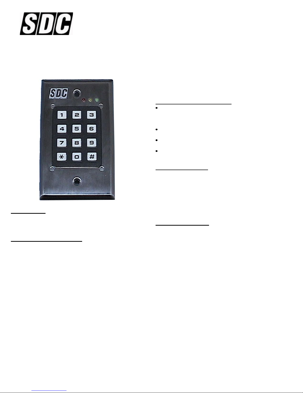
917 ENTRYCHECK STAND-ALONE KEYPAD
INSTALLATION INSTRUCTIONS
Self-test Diagnostics Mode
Enter the following sequence: 1 2 3 4 5 # 6 7 8 9 0 *. The red
and green LEDs should be alternately flashing. You do not
need to be in programming mode or know the master code to
run the self-test feature.
This test the keys, the LEDs, the microprocessor, and the
keypad memory.
After the test, either the red LED will indicate an error or the
green LED will show that no error was detected.
The keypad will resume normal operation once the red or
green LED status has been displayed.
Using This Manual
First, brackets and spaces are not part of the codes. They are used
here to clarify the operations and group like functions. Square
brackets are used to indicate that the keys inside the brackets are
to be pressed at the same time (requiring two keys to be pressed
simultaneously reduces the chance that someone will accidentally
get into programming mode). When entering a code in brackets,
first press the star key and, while holding down the star key, press
Description:
The 917 EntryCheck keypad operates on 12 or 24 volts AC or DC.
It offers over 1,000,000 possible user codes – from one to six
digits – to it’s 120 users and has a non-volatile EEPROM memory.
Understanding the LEDs:
The three colored lights above the keypad (LEDs) provide
information on the state of the unit. NOTE: A ‘slow’ flash is once
every two seconds, and a fast flash is once every second.
Green LED:
STEADY: Power on, no errors and no outputs are active.
SLOW FLASHING: No errors, at least one output is active.
FAST FLASHING: Keypad is programming mode.
Red LED:
STEADY: General error condition (usually caused by an
input error such as entering an invalid user code):
try again.
SLOW FLASHING: Error condition, at least one output is
active.
Yellow LED: For ADA requirements, the yellow LED keypress
indicator can be enabled during programming.
See the [*6] programming option for more details.
the second key. Release them both together.
Using This Keypad
Each user on the system is assigned two different codes/numbers.
The first code is the user number. This number (from 1 to 120) is
used to keep track of who is assigned to the system. All leading
zeroes are ignored. The second code is the PIN code (Personal
Identification Number). This is a 1 to 6 digit programmable code
that the user will enter into the keypad to activate certain functions.
This code can have leading zeroes as part of the code. This
information is recorded and stored in a safe place for future use.
The keypad can support a total of 120 users (user number 1
belongs to the Master User with a default PIN number of 1 2 3 4).
Recognizing the User: Because of the different PIN code lengths
that can be assigned to each user, it is necessary for the user to
press the (*) key after the PIN code has been entered. That tells
the electronics to verify the number entered. If the number entered
is validated, the outputs assigned to the user will be activated. For
example, to operate the keypad using the default master code of
1 2 3 4 (the only code that is pre-programmed with the unit) enter
1 2 3 4 *. While the door is unlocked, or whatever job your unit is to
perform, the green LED will blink at a slow rate.
Red & Green LEDs Alternately Flashing: Keypad is in SELF-
TEST DIAGNOSTIC MODE.
P:\INSTALLATION INST\Access Controls\INST-917\inst-917.vsd REV F 05-09 Page 1
Any suggestions or comments to this instruction or
product are welcome. Please contact us through
our website or email [email protected]
Page 4

How to Program Your 917 Keypad
Keep careful track of user numbers, whom they are assigned to,
assigned outputs, etc. as you program them. Keep the list in a safe
place. Press the buttons firmly. If you will be programming many
things at once, it may save time to temporarily assign a simple onedigit Master Code. Be sure to change back when you’re finished to
avoid compromised security. Whenever the * and any other character
are included in brackets [*x], press the * first and, while holding the *
down, press the other key. Release them both together.
[*1] Enter Program Mode (First Step)
Press * and 1 at the same time. Enter the Master Code (1 2 3 4 is the
factory default) then *. The green LED should now be rapidly flashing.
For example: [*1] 1 2 3 4 * will put you in the program mode. This
must be done for each program change.
[*2] Add/Change/Delete User (To add or change a User Code)
First, enter program mode (see first step).
Enter [*2], then the user number you wish to add or change (from 1 to
120 inclusive) followed by #, then the new PIN code (up to 6 digits)
followed by *, then the new PIN code again, followed by * (for
verification).
To change an output time:
First, enter program mode (see first step).
Enter [*3], then the time (0-255 seconds) followed by #, then the
output (0-6) followed by *.
For example: [*3] 3 0 # 0 * will assign a time of 30 seconds to
Output 0. Please note that you may change only
one output timer at a time.
[*4] Programming the Remote Trigger
The Remote Trigger activates the assigned Outputs at the press of a
remote doorbell-type button (momentary contact). A typical use would
be as a request-to-exit or it could be activated by a guard in response
to a Panic signal (see below) after verifying a person is authorized to
enter a secure area. There are four possible outputs: 0, 1, 2, and 3.
The Remote Trigger also activates the Key-Active output like any
normal key.
To select the Remote Trigger outputs:
First, enter program mode (see first step).
Enter [*4], then the outputs (023, 03 or 12 etc.) you wish the Remote
Trigger to activate, followed by the *. The choices for Outputs are:
0, 1, 2, and 3. If no outputs are entered, Remote Trigger will be
disabled.
For example: [*2] 4 4 # 2 1 2 5 *2 1 2 5 * will assign a user number
of 44 and a PIN code of 2125.
NOTE: [*2] 1# 38714* 3874* will change the Master Code to 38714.
Do not forget it.
To delete a User Code:
First, enter program mode (see first step).
Enter [*2], then the user number you wish to delete (from 2 to 120
inclusive), then press #, then *, then *.
For example: [*2] 7 5 # * * will delete the PIN code and all
assignments for user number 75
NOTE: The Master Code, which is the PIN code for user number 1
cannot be deleted but it may be changed.
[*3] Programming the Output (0-4) Timers
The output time is how long an output remains active when triggered.
The range is 0 to 255 seconds (maximum of 4 minutes 15 seconds).
If a time of 0 is entered, the output will toggle on/off each time it is
triggered or give a brief pulse as noted below.
Timer OUTPUT assignments:
TIMER TIME = 0 DEFAULT
Timer /Out0 (Main Relay) Toggle 5 sec
Timer /Out1 Toggle 15 sec
Timer /Out2 Toggle 25 sec
Timer /Out3 Toggle 35 sec
Timer /KeypadActive 7 msec pulse 10 sec
For example: [*4] 0 2 * will cause Remote Trigger to energize outputs
0 and 2.
NOTE: [*4] * will disable the Remote Trigger as no outputs are
assigned to it.
Please note that the default is all outputs active (0, 1, 2 and 3).
[*5] Programming the Panic Outputs
The Panic function triggers up to four outputs when the (*) and the (#)
keys are pressed together. If used outside the door, it can be used to
alert security that someone without a valid code seeks entry. If used
inside the door, it can act as a remote trigger. To comply with NBFAA
false alarm guidelines, this method of triggering an output should not
be used to send panic signals to a remote monitoring station.
To select the Panic outputs:
First, enter program mode (see first step).
Enter [*5], then the outputs (013, 23 or 12 etc.) you wish the Panic to
trigger, followed by the (*). The choices for outputs are 0, 1, 2, and 3.
If no output is entered, the Panic function will be disabled.
For example: [*5] 0 1 2 3 * will assign outputs 0-3 to the Panic
function.
[*5] 3 * causes output 3 to be assigned to the Panic function.
NOTE: [*4] * Output 3 is active as a factory default for the Panic
function.
P:\INSTALLATION INST\Access Controls\INST-917\inst-917.vsd REV F 05-09 Page 2
Page 5

[*6] Programming the Yellow LED: On/Off
When on, the yellow LED lights when any key is pressed.
First, enter program (see first step).
Enter [*6] then 1 or 0 (1 enables the yellow LED and 0 disables it),
then *.
For example: [*6] 0 * will turn the yellow LED off (the default is ON).
[*7] Enable/Disable ALL PIN code Access
When disabled, no PIN (including the Master Code) will activate the
outputs. Programming functions, Remote Trigger and Panic are not
disabled. This can be used to immediately control all access while
changing selected user codes in case of a security problem.
To disable all user access:
First enter program mode (see first step).
Enter [*7], then 0 or 1 (0 to disable user access and 1 enables it), then
* (the default is ENABLED).
For example: [*7] 0 * will disable all user codes.
[*7] 1 * will re-enable all user codes.
Troubleshooting Tips:
If you make an input error (e.g. if you enter a non-existent User
Code) and press the star key, the red LED will light. Simply start
over.
Do not make the mistake of thinking you have to ‘clear’ the red
LED if you make an error. Just re-enter the correct number. The
red LED will clear automatically.
If you make an input error before entering *; wait 5 seconds and
the command memory will be cleared automatically (or press # to
clear manually). Start again.
Five operating errors within 60 seconds will trigger the Auto
Lockout function, disabling the keypad for 4 minutes and 15
seconds (255 seconds).
Be sure you are pressing the buttons firmly. The yellow LED
should come on with each key pressed, unless that feature has
been disabled.
[*8] Programming the Keypad Active Output: On/Off
When on, the first key pressed for any reason triggers the Output 4 for
the length of time set above. It is intended to activate an overhead
light, surveillance camera etc..
To program the Keypad Active Output:
First, enter program mode (see first step).
Enter [*8] 0 * then 0 or 1 (0 for ON or 1 for OFF) then *.
For example: [*8] 0 * will disable Keypad Active (the default
is ENABLED).
[*9] Erase Keypad Memory/Reset ALL to Factory
Default Settings (use with caution).
This is used when most or all or the programming has to be changed,
as when a keypad has been moved to a new location.
To reset all programming to factory defaults:
First, enter program mode (see first step).
Enter [*9] then *.
For example: [*9] * will immediately and permanently clear the
entire memory. There is no reprieve.
Be careful.
[*0] Assign Selected Outputs to Users
This will allow you to assign any combination of the four Outputs. If
no Outputs are selected, then all Outputs will be disabled for this user
number. This feature can be used to temporarily disable a user
without having to delete the user from the memory.
First, enter program mode (see first step).
Enter [*0], then (UID code) followed by #, then desired Outputs, (0 to
3) followed by *.
For example: [*0] 1 0 9 # 0 2 3 * will assign Outputs 0, 2 and 3 to
User 109.
[*0] 6 4 # * will assign assign no outputs to User 64.
Factory Default Settings:
If the settings have not been changed after shipment, or if they have
been reset, they are as follows:
Master Unit #1 – Code is 1 2 3 4.
Remote Trigger will activate Main Relay/Output
0, Output 1, Output 2 and Output 3.
Panic Trigger will activate Output 3.
All Outputs are set for a timed Operation:
Main Realy/Output 0 = 5 seconds
Output 1 = 15 seconds
Output 2 = 25 seconds
Output 3 = 35 seconds
Yellow LED/Sounder enabled.
Keypad Active enabled.
NOTE: Whenever the * and any other character are included in
brackets [*x], press the * first and, while holding the * down, press the
other key. Release them both together.
Notes:
Keeping records: the User number (1-120) is not the same as the PIN
CODE. You should keep a record of your User numbers vs. User
names.
The correct use of the green LED is to indicate an entry is unlocked.
If the installation does not use a separate annunciator/light to indicate
to the end-user the the entry is unlocked, it is important that all PIN
codes be programmed to activate only one output (Door Lock). If
more than one output is needed, such as an ALARM disable, then
both outputs should be programmed for the same time-out to avoid
any confusion by the next user.
P:\INSTALLATION INST\Access Controls\INST-917\inst-917.vsd REV F 05-09 Page 3
Page 6
ORANGE/BLACK
PINK/BLACK
GRAY/BLACK
WHITE
GRAY
VIOLET
BLUE
GREEN
YELLOW
ORANGE
RED
BLACK
J4
1
J3
1
1
USER I/O WIRING HARNESS
DEFAULT RESET
REMOTE TRIGGER RETURN
REMOTE TRIGGER
OUOT3/PANIC [SINK 500 mA]
OUT2 [SINK 500mA]
OUT1 [SINK 500mA]
KEY ACTIVE [SINK 50mA]
J2
U3U1
U2
J6
J1
RELAY
NC
CNO-+
GROUND
+V FILTERED
GREEN-LED
RED-LED
YELLOW-LED
1
J5
USER I/O
CONNECTOR
REMOTE TRIGGER
NORMAL OPEN
TWISTED P AIR
MOV
12/24V AC/DC
POWER SUPPLY
12
11
10
9
8
7
J5
6
5
4
3
2
1
MAGNETIC
DOOR LOCK
(FAIL SAFE)
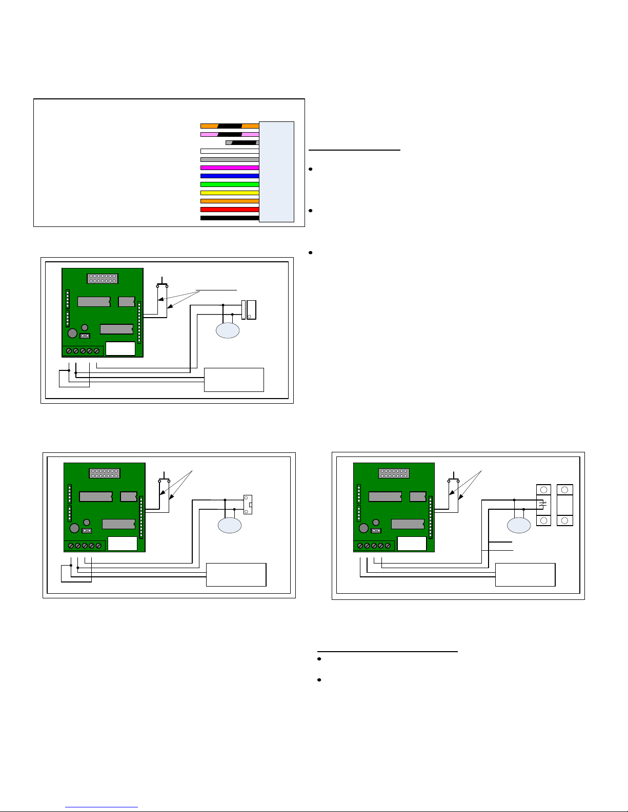
Installation Tips:
System Wiring Recommendations
The REMOTE TRIGGER LINE should be wired with either TWISTEDPAIR wire or SHIELDED wire to reduce the chance of noise problems.
If using SHIELDED wire, tie the shield to the ground at one end only –
preferably the power supply ground.
All ground and signal return line should terminate at only one place,
that being the POWER SUPPLY GROUND. This will keep GROUND
CURRENT noise to a minimum. This can be in the form of a common
ground lug near the power supply or Alarm Control Panel.
Install MOV device as close to the actuator (door lock, etc.) as
possible to prevent kickback voltage from damaging the keypad.
When installing the 917 keypad in a single-gang metal box (1.8"W x 2.9"H).
place insulating tape on the housing near the location of J1 on the board.
As the spacing is tight, this will prevent any strands of wire from shorting to
the metal box. Also ensure that the FRONT of the metal box is mounted
FLUSH with the front of the wall stud and NOT flush with the sheetrock. It
is RECOMMENDED that all new installations be mounted in a standard
plastic, single-gang box.
ELECTROMAGNETIC DOOR LOCK
J2
J4
1
J3
U1
1
J6
1
J1
CNO-+
U3
U2
1
J5
RELAY
NC
USER I/O
CONNECTOR
ELECTROMAGNETIC DOOR STRIKE
REMOTE TRIGGER
NORMAL OPEN
TWISTED PAIR
MOV
12/24V AC/DC
POWER SUPPLY
ELECTRIC
DOOR STRIKE
(FAIL SECU RE)
J2
J4
1
J3
U1
1
J6
1
J1
CNO-+
U3
U2
1
J5
RELAY
NC
USER I/O
CONNECTOR
REMOTE TRIGGER
NORMAL OPEN
TWISTED PAIR
MOV
To Alarm
Panel
12/24V AC/DC
POWER SUPPLY
Shunting a normally closed zone
External Device Current Limits
The SINK capability of 500mA applies to 12V AC/DC or
REGULATED 24VDC power and jumper J6 installed.
For unregulated 24VDC or AC supplies, derate the SINK current
to 50mA and REMOVE jumper J6.
P:\INSTALLATION INST\Access Controls\INST-917\inst-917.vsd REV F 05-09 Page 4
Page 7
J2
J4
1
J3
U1
1
1
J1
CNO-+
U3
U2
J6
RELAY
NC
1
J5
USER I/O
CONNECTOR
TYPICAL ALA RM
CONTROL PANEL
ARM/DISARM
TERMINALS
+12 VOLTS
-12 VOLTS
Specifications
Mechanical
Board Dimensions: 1.75" W x 2.8" H x 1.0" D
Environmental
Temperature: -20F to +130F (-28c to + 54C)
Humidity: 90%
Features
Low cost, Easy to Use.
Single-Gang, Flush-mount Design
12-24V AC/DC Operation
120 Users, 1- to 6- Digit Codes
ARMING/DISARMING
A TYPICAL CONTROL PANEL
On-Board 6 amp Form “C” Relay
5 individual Outputs
5 User-Programmable Timers
Error Key Lockout
Non-Volatile EEPROM Memory
J2
Easy-to-Use Front programming
Indoor use
J4
1
J3
U1
1
1
U2
J6
J1
RELAY
NC
CNO-+
U3
11
USER I/O
CONNECTOR
1
J5
AUXILIARY RELAY
+12/24
KEY ACTIVE OUT1/2/3
SEE USER I/O WIRING
HARNESS FOR PINOUT
12/24V AC/DC
POWER SUPPLY
NO
NC
C
Electrical
Supply Voltage
12 or 24 volts AC or DC
@ 12 volts AC/DC – jumper J6 installed
@ 24 volts regulated DC – jumper J6 installed
@ 24 volts AC/DC unregulated – jumper J6 removed
Max. supply voltage – 28V AC/DC – jumper J6 removed
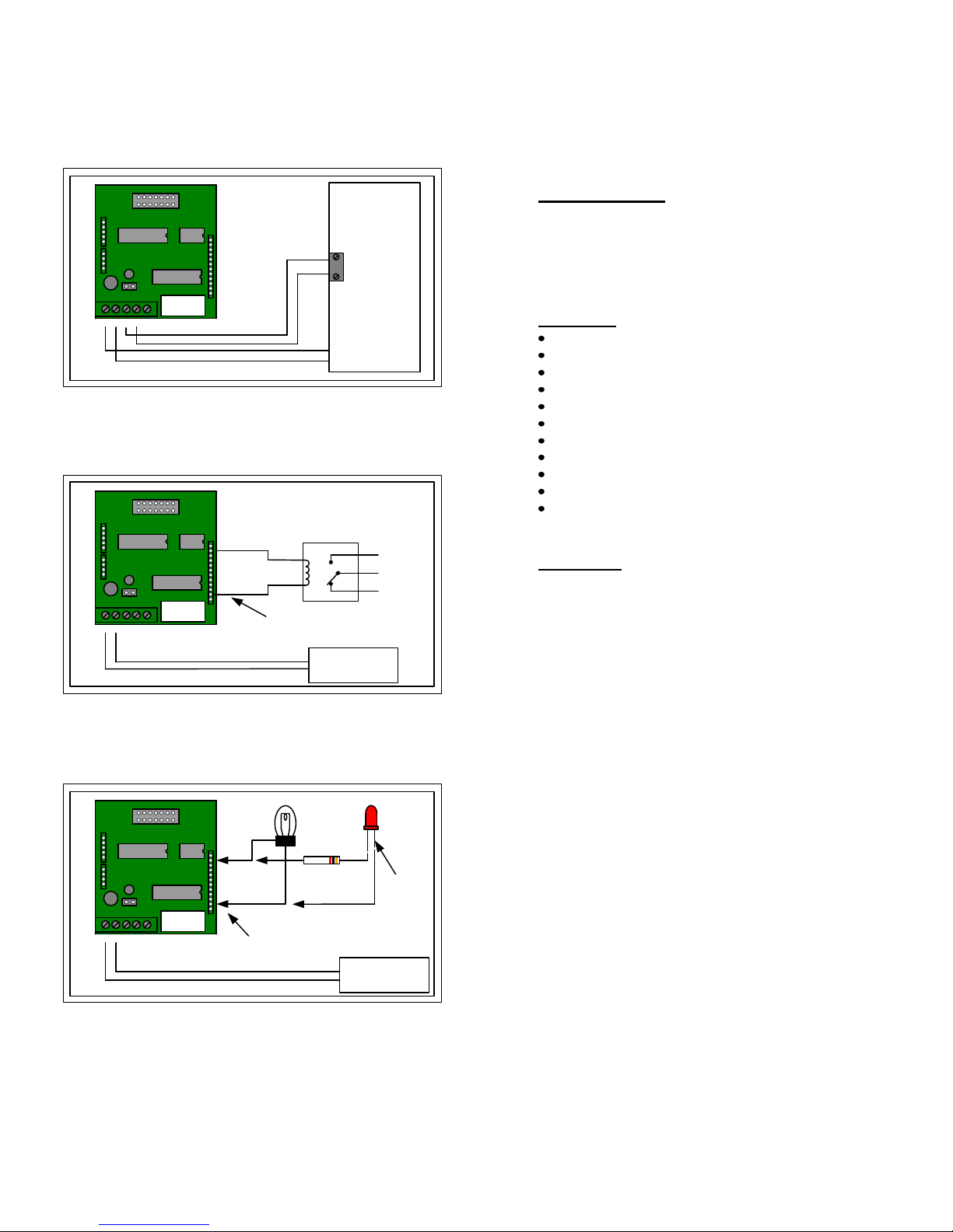
AUXILIARY RELAY WIRING
J2
J4
1
J3
U1
1
1
J1
CNO-+
U3
U2
J6
RELAY
NC
LAMP
+12
11
USER I/O
CONNECTOR
1
J5
KEY ACTIVE OUT1/2/3
SEE USER I/O WIRING
HARNESS FOR PINOUT
LED
1K 1/4W
RESISTOR
OBSERVE MAXIMUM
CURRENT LIMITS!!!
CATHODE
12/24V AC/DC
POWER SUPPLY
EXTERNAL LAMP WIRING
P:\INSTALLATION INST\Access Contro ls\INST-917\inst-917.vsd REV F 05-09 Page 5
Output Current Limits
@ 12VDC 500mA (sink)
@ 24 VDC regulated 500 mA (sink)
@ 24 unregulated (J6 removed) 50 mA (sink)
MAIN-RELAY – 10amp surge, 6amp continous @ 30VDC
Maximum Wire Size for J1 – 16AWG
General Keypad Limits
Remote Trigger minimum ON time – 100ms
Keypad Debounce time – 100ms
Keypad life – 1,000,000 operations per key
User Memory write cycle limit – 1,000,000 cycles
User Memory retension > 40 years
Applications
Storage closets Machinery Controls
Residential/Commercial Doors Self-Storage Facilities
Multi-Tenant Buildings Pools/Saunas
Recreation Centers Restaurant Freezers
Safe Rooms Computer Rooms
 Loading...