

Page 1
801 Avenida Acaso, Camarillo, Ca. 93012 • (805) 494-0622 •
www.sdcsecurity.com • E-mail: [email protected]
INSTALLATION INSTRUCTIONS EH SERIES
ELECTRICAL
ELECTROMAGNETIC DOOR HOLDER
This product is a high quality electromagnetic holding device intended for use in fire door
applications, but can be used for other magnetic applications.
PLEASE READ INSTRUCTIONS CAREFULLY!
PERFORMANCE DATA
MODEL
1224
24120
24220
VOLTAGE DC / mA AC / mA TERMINALS Lb. Kg.
12 V
24 V
24 V
120 V
24 V
220 V
40
40
20
-
20
-
38
36
19
20
19
15
C & L
C & H
C & L
C & H
C & L
C & H
30
30
40
35
20
22
13.6
13.6
18.1
15.8
9.0
9.8
HIGH HOLDING FORCE / SPECIAL APPLICATIONS:
MODEL
1224
24120
VOLTAGE DC / mA AC / mA TERMINALS Lb. Kg.
24 V
120 V
85
-
81
100
C & L
C & L75110
34.0
49.8
To obtain performance values in table above, apply high
listed voltage to low voltage terminals (C & L).
NOTE: This configuration can only be applied to Models
1224 & 24120.
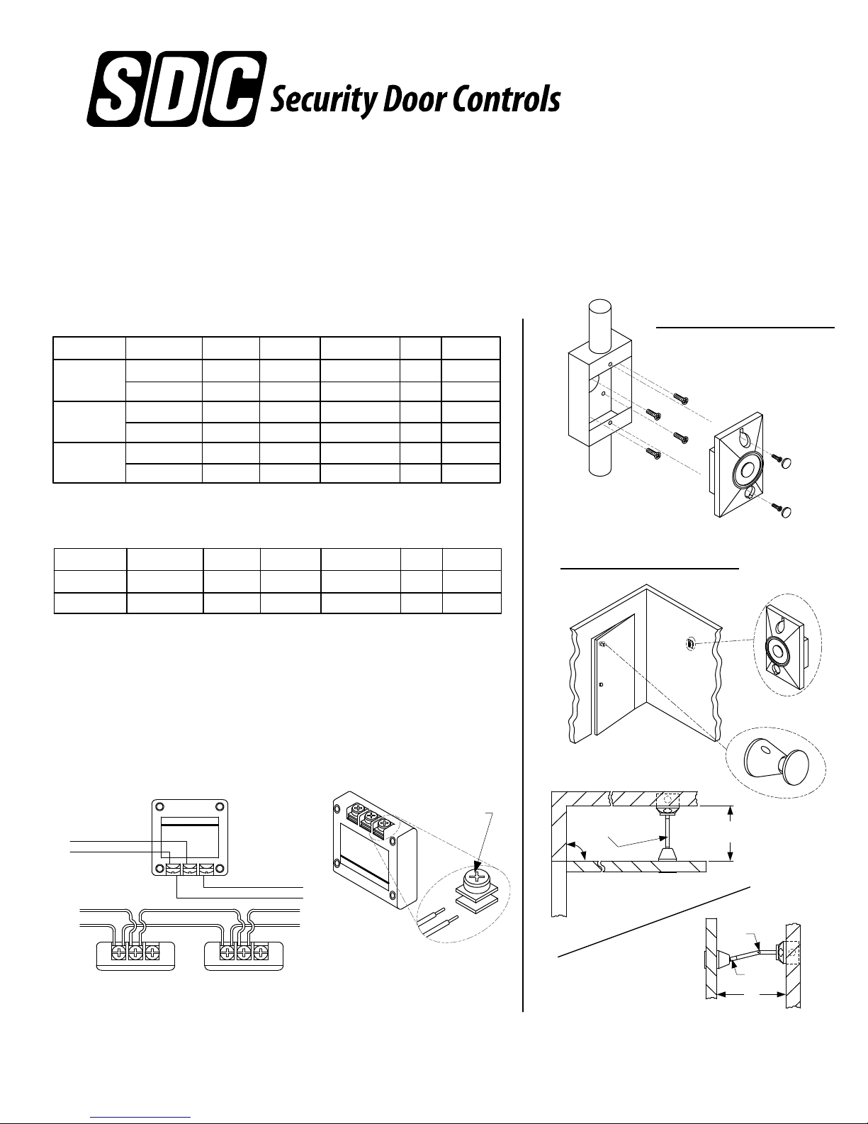
SURFACE MOUNTING
GENERAL MOUNTING
C -COMMON
L – LOW VOLTAGE
H – HIGH VOLTAGE
LOW VOLTAGE
POWER INPUT
P:\INSTALLATION INST\ACCESSORIES\INST-EH SERIES.vsd REV C 10-14 Page 1
L H
C
HIGH VOLTAGE
TO NEXT UNIT
#6-32 SCREW &
SEM PLATE
WALL
EXAMPLE:
5" OVERALL DISTANCE
USE EHR2 (2" EXTENSION)
o
90
EXTENSION:
TO CALCULATE EXTENSION LENGTH;
SUBTRACT 3" (117mm) FROM WALL TO
DOOR AT DESIRED ANGLE.
DOOR
MIS-ALIGNMENT
Any suggestions or comments to this instruction or
product are welcome. Please contact us through
our website or email [email protected]
5"
[127mm]
EHRA4
EHR1
8"
[203mm]
Page 2
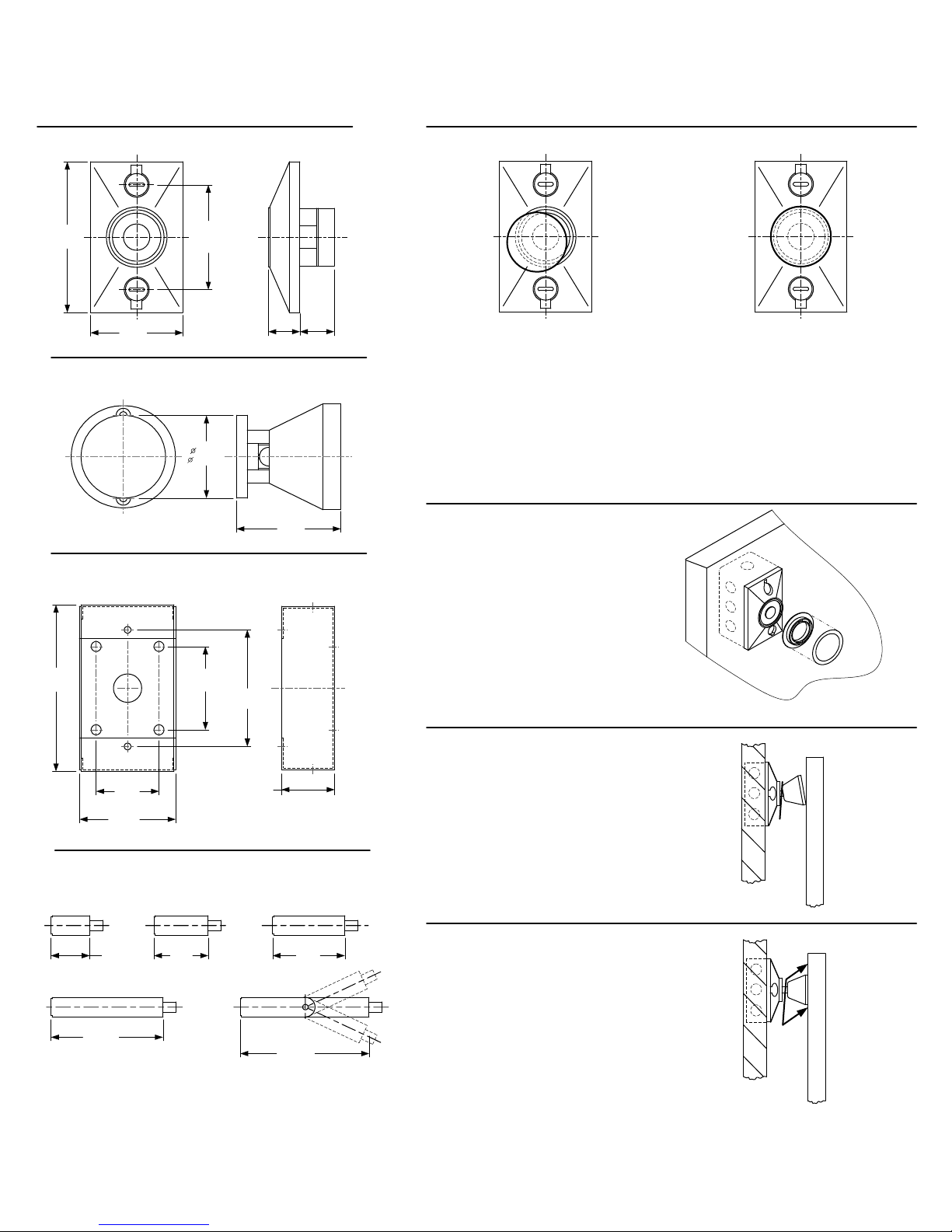
GENERAL DIMENSIONS
DOOR MAGNET
ASSEMBLY INSTRUCTIONS
CATCH PLATE MOUNTING
4-5/8”
[117.5mm]
2-3/4”
[70mm]
3-5/16”
[84.1mm]
CATCH PLATE ASSEMBLY
1-3/4”
[ 44.5mm]
SURFACE MOUNT BACK BOX
4-5/8”
[117.5mm]
2-3/8”
[60mm]
3-5/16”
[84mm]
15/16”
[24mm]
2-1/8”
[54mm]
1-1/16”
[27mm]
WRONG
STEP 1:
With door magnet securely
fastened, aligned and energized,
proceed with swivel base
assembly.
NOTE: If door extensions are
required, install before step 2.
STEP 3:
With catch plate assembly
attached magnetically to door
magnet, peel adhesive backing
off mounting template and slide
over catch plate, making sure
adhesive side faces door.
RIGHT
STEP 2:
Attach swivel portion to magnet,
being careful to center the catch
plate over the magnet.
L
L
A
W
1-3/4”
[44.5mm]
2-3/4”
[70mm]
1-1/2”
[38.1mm]
EXTENSION RODS
EHR1 EHR15 EHR2
1”
[25.4mm]
EHR3
3”
[76.2mm]
PART NUMBER + A = CHROME // PART NUMBER + C = BRASS
P:\INSTALLATION INST\ACCESSORIES\INST-EH SERIES.vsd REV C 10-14 Page 2
1-1/2”
[38.1mm]
EHRA4
[50.8mm]
4”
[101.6mm]
2”
WALL
STEP 4:
Gently close door and with one
hand adjust base of catch plate
to lie flat against the door.
STEP 5:
While keeping slight pressure on
door, slide mounting template
over catch plate to door surface
and apply pressure to template
in a few spots.
WALL
WALL
DOOR
DOOR
Page 3
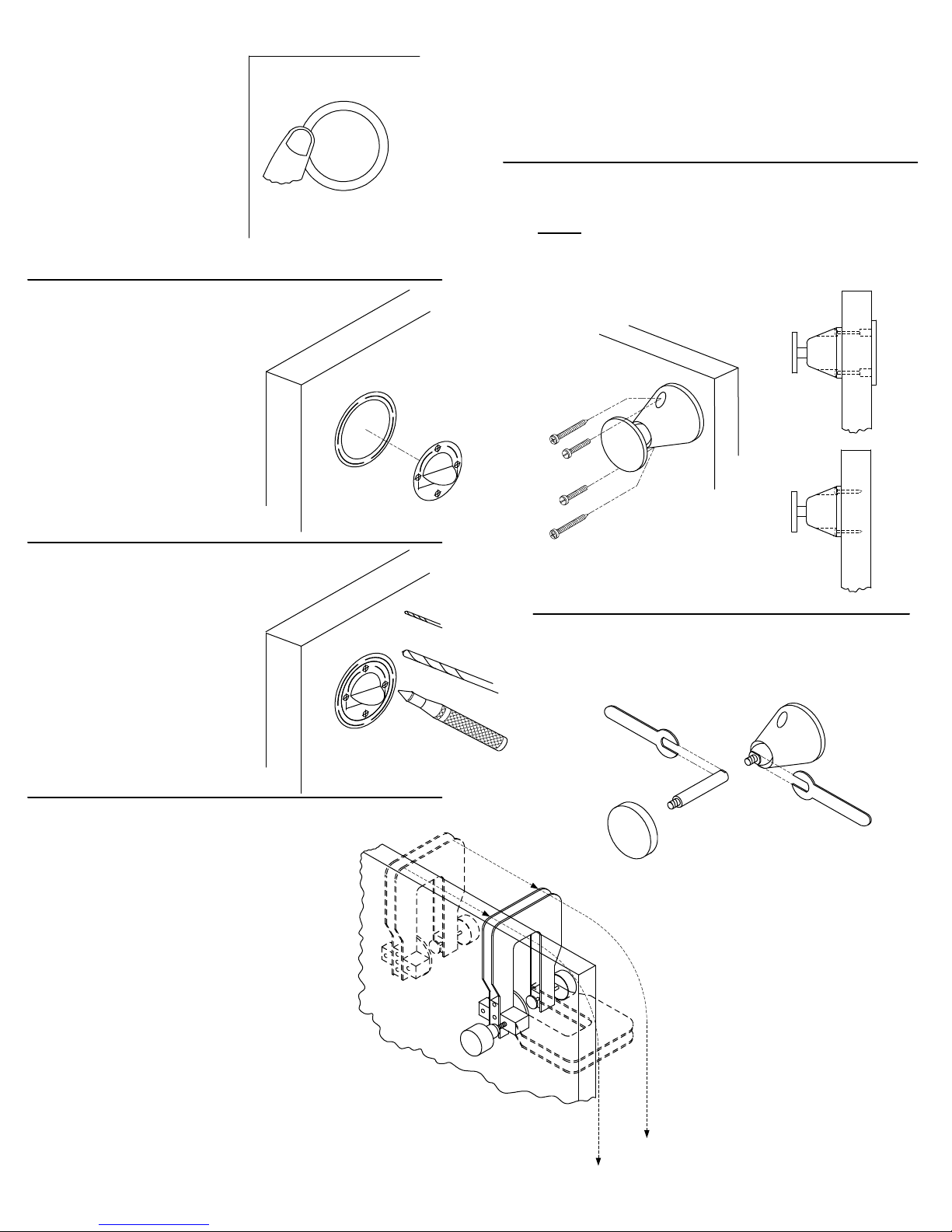
STEP 6:
Opening door will reveal
mounting template. Apply
final pressure to insure
template does not fall off
while assembly takes place.
DOOR
STEP 8C:
G
T
N
I
E
T
M
N
P
U
O
M
R
E
A
L
A
T
E
S
N
O
I
T
C
D
U
R
I
N
T
S
If mounting catch plate assembly directly to door, drill
1/8”dia. pilot hole approximately 1 to 1-1/2” deep,
being careful not to go through door.
STEP 9:
For either style of mounting (thru door/direct) remove
ONLY alignment template, then place swivel in center.
Align holes, then insert screws and tighten assembly
fully. Lastly, remove mounting template.
STEP 7:
Insert alignment template into
center of mounting template.
Use tab to rotate to fine
adjustment. While holding
alignment template with one
hand, remove adhesive
backing of tab, then push flat
against door.
STEP 8 A:
If not using door assembly
drill fixture, center punch
points indicated on
alignment template for either
horizontal or vertical
mounting. For best results,
drill 1/8” pilot holes first, then
follow with 5/16” dia drill.
R
O
O
D
DOOR
DOOR
R
O
O
D
1/8”
CATCH PLATE EXTENSION ROD
5/16”
ASSEMBLY:
STEP 8 B:
If using door assembly drill fixture,
alignment template is not required.
Locate drill bushing end into mounting
template, holding firmly flat against door,
then tighten slightly. Make sure fixture is
flat against edge of door, tighten fully and
drill through using 5/16” dia. drill.
P:\INSTALLATION INST\ACCESSORIES\INST-EH SERIES.vsd REV C 10-14 Page 3
 Loading...