

Page 1
801 Avenida Acaso, Camarillo, Ca. 93012 • (805) 494-0622 •
www.sdcsecurity.com • E-mail: [email protected]
INSTALLATION INSTRUCTIONS
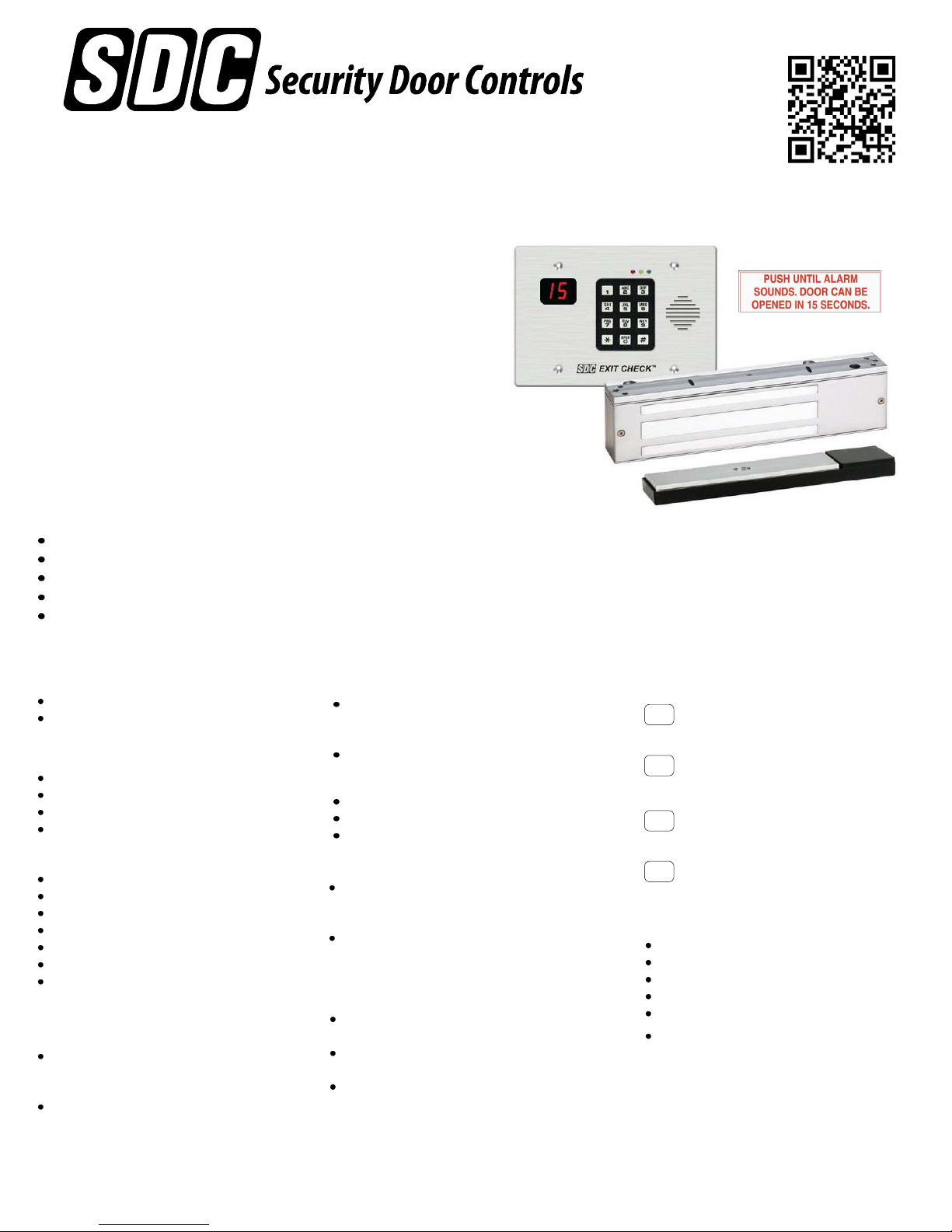
101-DE/101-KDE
Verbal Exit Instructions or
Alarm Tone Only and
Digital Countdown Display
Application:
When unauthorized egress is initiated SDC
through the door for 15 seconds (or 30 seconds). Meanwhile, the person
exiting must wait while personnel or security responds. The door unlocks
after 15 seconds have elapsed permitting egress. When powered by a fire
control supervised power supply, the lock will release immediately in an
emergency. The integral digital keypad eliminates the need to carry and
locate keys for reset and bypass functions.
Exit Check
Exit Check®applications include:
Restricting the egress of wandering patients for their own safety.
HUGS®Infant Protection System compatibility
Restricting the egress of commercial center patrons for security application needs.
Controlling pedestrian traffic in transportation facilities, including airport jetways and tarmacs
Reducing Shoplifting and Employee Theft
®
delays egress
Features:
Egress Delay
15 or 30 second exit delay
1 or 2 second nuisance delay
Built-In 3 Function keypad
Alarm and lock reset
1 to 30 second bypass
Sustained bypass
Additional keyswitch optional
Built-In Annunciation
Armed mode
Nuisance mode
Irreversible egress mode
Release mode
Digital countdown mode
Field selectable voice notification or tone
Field selectable male voice with security
message or female voice with safety
message
Triggering Options
Egress alarm triggered by door
movement when used with SDC
1500DE series EMLocks.
Trigger input from external device
field selectable (N/O or N/C)
P:\INSTALLATION INST\Delayed Egress\INST-101DE_KDE.vsd Rev D 09-14 Page 1
Control Inputs
1 to 30 second request-to-exit and bypass
input with anti-tailgate and jumper
selectable door prop alarm.
Reset
Monitoring Outputs
Armed mode
Egress initiation status
Released status
Optional EMLock Outputs
Door position sensor – indicates door
open and door closed, commonly used to
verify egress after release.
Magnetic bond sensor – indicates locked
with full holding force, low holding force,
unlocked and tampering.
Choice of Mounting
Recessed mounted
(3 gang metal plaster ring included)
Surface mounted with optional 3 gang
box (DEC-J)
Optional shroud (SHD-J) to be used with
DEC-J surface box.
Display Modes
15
Door armed and locked.
Alarm countdown has ended,
door is unlocked and alarm sounding
00
until reset.
Door unlocked and alarm is shunted
- -
(REX or Bypass)
Door has been opened after REX,
- -
- -
- -
Bypass or Alarm.
Code Compliance
IFC International fire Code
IBC International Building Code
NFPA 101 Life Safety Code
NFPA 1 Uniform Fire Code
California Building Code
Field selectable automatic or manual
power up after emergency release or
power loss. Use of manual power up
complies with California Building Code
(OSHPD) requirements.
Any suggestions or comments to this instruction or
product are welcome. Please contact us through
our website or email [email protected]
Page 2
101-DE/101-KDE Operational Description
The door is closed and secured by latching hardware. The model 101-DE/101-KDE Exit Check controller sends power
to the magnetic lock or Delayed Egress Panic Device to lock the door in the secured position. The integral digital
display shows the unlock delay time.
Activation / Alarmed Release :
Activation of the Exit Check’s trigger input initiates the 15 or 30 second unlock cycle . A pre-activation warning tone is
sounded during the short nuisance delay period and the integral display starts counting down. To prevent false alarms,
removing the trigger input activation during the nuisance delay period will silence the pre-activation warning tone, reset
the countdown display and keep the door locked.
Once the nuisance delay period has been exceeded, the Exit Check continues to count down during an irreversible
door release cycle. The integral digital countdown display and voice commands continue to inform the person intending
to exit of the seconds remaining until unlock. An alarm output is activated to alert personnel of an unauthorized exit.
After the 15 or 30 second delay cycle has expired, the Exit Check will remove power to the locking device, releasing the
door and allowing free egress.
Reset / Relock:
The Exit Check can be manually reset by authorized personnel by closing the door and entering a code on the integral
digital keypad, momentarily turning the optional reset key switch to the reset position or by momentarily activating a N/O
switch connected to the remote reset terminals.
Request to Exit / Authorized Bypass:
A Request to Exit cycle is initiated by entering an authorized REX code on the integral digital keypad, momentarily
turning the optional key switch to the bypass position or momentarily activating a N/O switch connected to the REX
terminals. The power will be removed from the locking device allowing free egress. After the request to exit cycle has
expired, the Exit Check will automatically reapply power to the locking device to re-secure the door.
Unlocking the door for extended periods of time (Authorized Bypass mode) is accomplished by entering an Authorized
Bypass code on the integral keypad, momentarily turning the optional key switch to the Bypass position or placing a
maintained closure across REX terminals. Releasing the closure across the REX terminals will restart the Request to
Exit cycle. Entering the Reset code on the integral digital keypad, or momentarily turning optional key switch to the
Reset position will immediately reapply power to the locking device to re-secure the door.
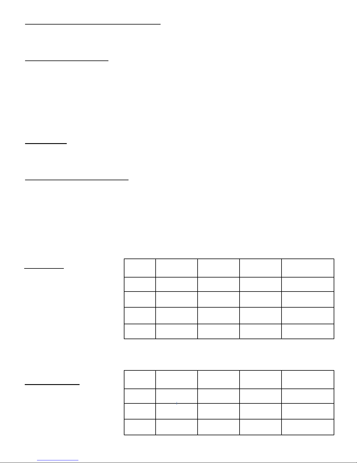
(NFPA-101)
The 101-DE/101KDE operation
complies with the following building
and fire codes: NFPA 101; NFPA 1UFC; UBC; IBC; IFC; SBC;
California Building Code. Listings:
UL Listed: Special Locking
Arrangements and Auxiliary Locks;
California State Fire Marshal
(CSFM) Listed.
Option
Code
NA
ND
NH
NC
(CBC Compliant)
Delay Release
Time
15 sec or 30 sec
Selectable
15 sec
Fixed
30 sec
Fixed
Fixed
Nusiance
Time
1 sec or 2 sec
Selectable
0 sec or 1 sec
Selectable
0 sec or 1 sec
Selectable
0 sec or 1 sec
Selectable
Reset after
Alarm
Manual
Manual
Manual
Manual15 sec
Lock Status on
Power-Up
Locked or Unlocked
Selectable
Locked or Unlocked
Selectable
Locked or Unlocked
Selectable
Unlocked
Fixed
Per BOCA compliance, the Exit Check is manually reset by authorized personnel after an alarm by closing the door and
actuating the integral reset key switch or by momentarily closing a contact connected to the remote reset terminals. In
addition, reset will be automatically initiated once the door has been opened, then closed and remains closed for 30
consecutive seconds.
(BOCA/Chicago)
Code
The 101-DE/101-KDE operation
Option
complies with BOCA National
BD
Building Code and the Chicago
Building Code: UL Listed, Special
BH
Locking Arrangements and Auxiliary
Locks.
P:\INSTALLATION INST\Delayed Egress\INST-101DE_KDE.vsd Rev D 09-14 Page 2
BC
Delay Release
Time
15 sec
Fixed
30 sec
Fixed
15 sec
Fixed
Nusiance
Time
0 sec or 1 sec
Selectable
0 sec or 1 sec
Selectable
0 sec
Fixed
Reset after
Alarm
Auto/Manual
Auto/MAnual
Auto/Manual
Lock Status on
Power-Up
Locked or Unlocked
Selectable
Locked or Unlocked
Selectable
Locked or Unlocked
Selectable
Page 3
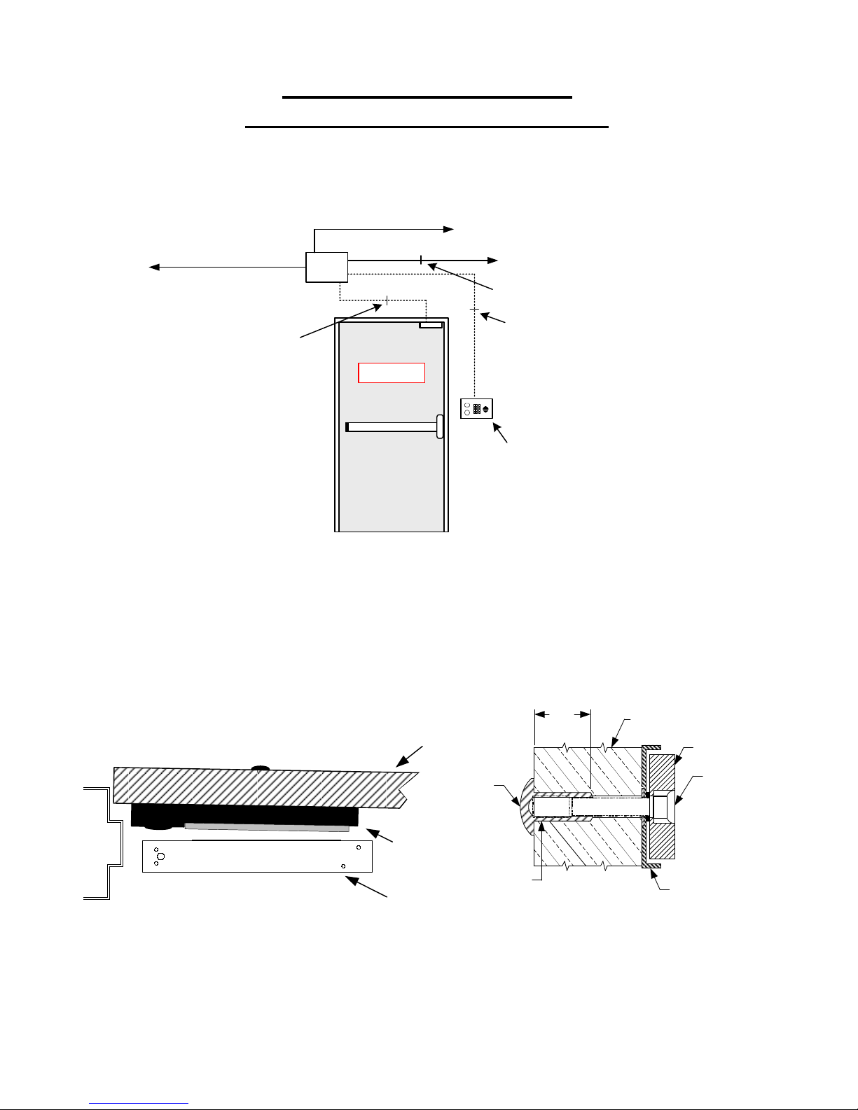
Typical System Wiring –
Single Door w/ Latching Hardware
WARNING:
APPLICATION OF VOLTAGE TO THE DRY CONTACT INPUTS OF THIS UNIT
WILL CAUSE PERMANENT DAMAGE AND VOID THE WARRANTY
2 conductors
To Smoke Detection
System – Dry, Closed
Contact
4 conductors
3 conductors
Power
Supply
PUSH UNTIL ALARM
SOUNDS. DOOR CAN BE
OPENED IN 15 SECONDS.
AC Mains
To Fire Panel – Dry, Closed Contact
2 conductors
6 conductors
101-DE
101-KDE
Models: 1511DE, 1571DE & 1581DE
Note: Armature assembly with tray
required for proper operation of the
trigger switch.
Mount magnet and armature
tray assembly per template
P:\INSTALLATION INST\Delayed Egress\INST-101DE_KDE.vsd Rev D 09-14 Page 3
Door
Armature tray
assembly
EMLock
SEX NUT
1/2”
1–1/4"
DOOR
ARMATURE
5/16 – 18
ARMATURE
MOUNTING
SCREW
ARMATURE HOLDER
Page 4
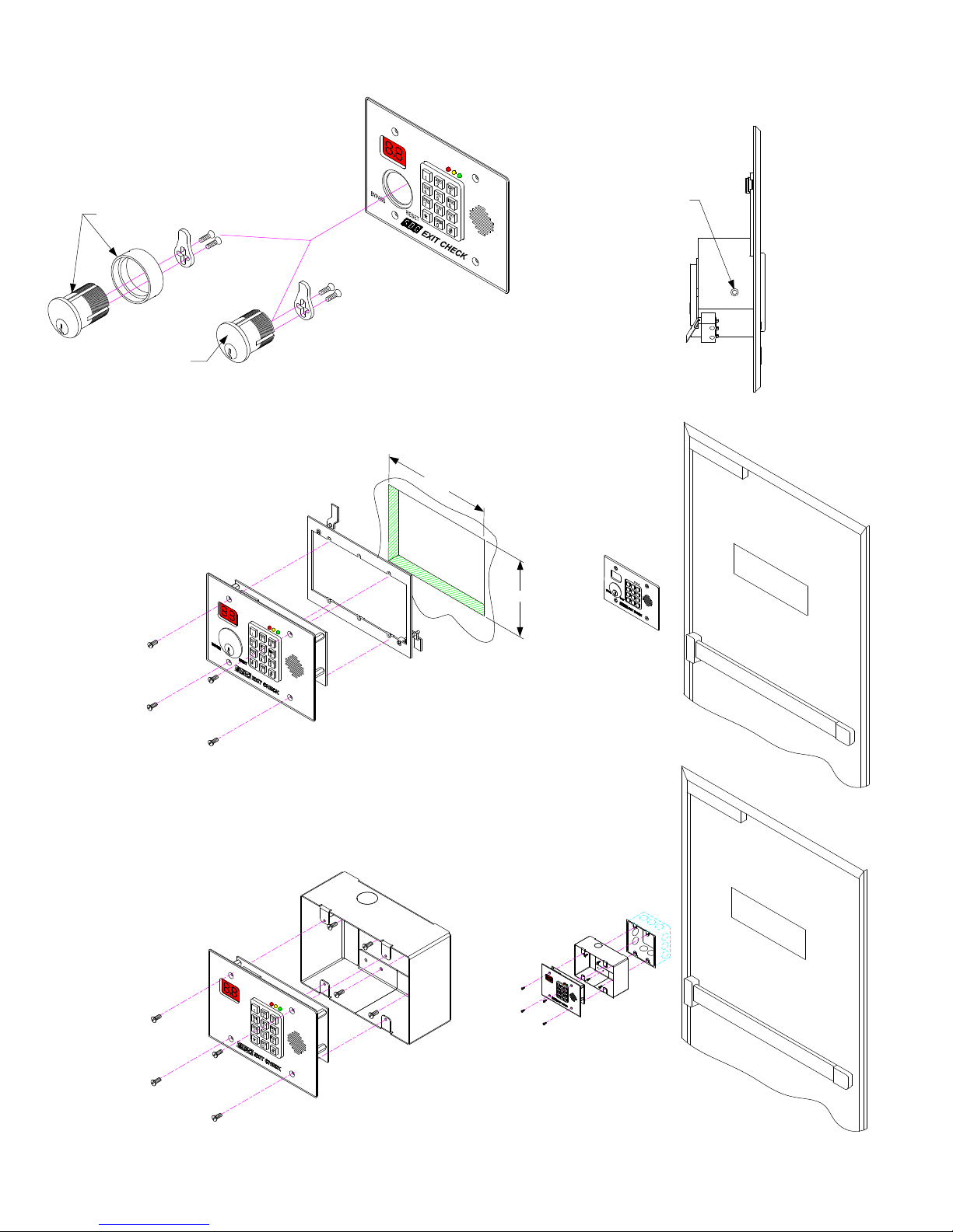
1-1/4” KEY CYLINDER
REQUIRES COLLAR
1-1/8” KEY CYLINDER
7185SC1-26D-KD
1) Cut hole in dry wall to
dimensions shown.
2) Mount wall bracket
over hole.
KEY CYLINDER INSTALLATION
(KDE Model Only)
WITH KEY CYLINDER IN PROPER
POSITION INSIDE SWITCH BLOCK,
TIGHTEN THE SET SCREW TO
LOCK CYLINDER IN PLACE.
RECESSED MOUNTING
DRY WALL
5-3/4”
3) Carefully insert unit and
secure with screws
supplied.
2) Carefully insert unit and
secure with screws
supplied.
3-3/4"
SURFACE MOUNT 3 GANG BOX OVER
EXISTING RECESSED 2 GANG BOX
1) Attach optional 3 Gang Surface
Mount Box to existing recessed 2 gang
box using screws supplied.
P
U
S
H
D
U
O
N
O
T
I
R
L
A
C
L
A
A
N
R
B
M
E
S
S
O
O
E
P
C
U
E
O
N
N
N
D
E
D
S
D
.
S
I
N
.
1
5
P
U
S
H
D
U
O
N
O
T
I
R
L
A
C
L
A
A
N
R
B
M
E
S
S
O
E
O
P
C
U
E
O
N
N
N
D
E
D
S
D
S
.
I
N
.
1
5
P:\INSTALLATION INST\Delayed Egress\INST-101DE_KDE.vsd Rev D 09-14 Page 4
Page 5
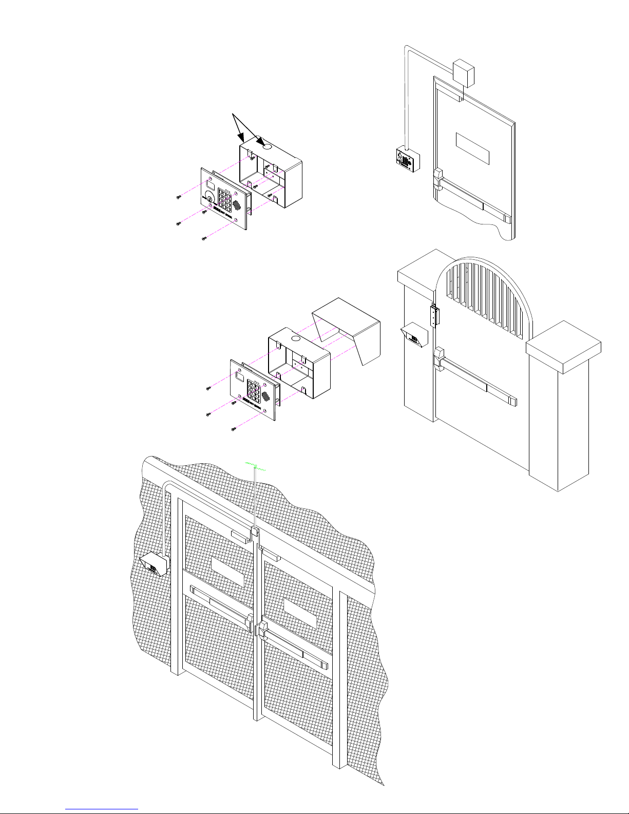
1) Attach optional 3 Gang Surface
Mount Box to wall using
screws supplied.
1a) Knockouts are located on
two surfaces of the box to
allow wire conduit insertion.
2) Carefully insert unit and
secure with screws
supplied.
1) Use optional 3 Gang Box inside
optional Shroud as a template to
drill pilot holes through
shroud and into post (or wall).
SURFACE MOUNT
3 GANG BOX
TO WALL
OUTSIDE WALL or
POST MOUNTING
with WEATHER SHROUD
P
U
S
S
H
O
U
U
N
N
O
T
D
I
P
L
S
A
E
.
D
N
L
A
O
E
R
D
O
M
I
R
N
C
1
5
A
S
N
E
B
C
E
O
N
D
S
.
2) Mount 3 Gang Box and Shroud
to Post with screws supplied.
3) Carefully insert unit and
secure with screws
supplied.
To
Power
Supply
P
U
S
S
H
O
U
U
N
N
O
T
D
I
L
P
S
E
A
.
D
N
L
A
O
E
R
D
O
M
R
I
N
C
1
5
A
S
N
E
B
C
E
O
N
D
S
.
P
U
S
S
H
O
U
U
N
N
O
T
D
I
P
L
S
E
A
.
D
L
N
A
O
E
R
D
O
M
I
R
N
C
1
5
A
S
N
E
B
C
E
O
N
D
S
.
101-DE CONTROLLERS ARE
CAUTION:
DESIGNED FOR INDOOR USE.
UNIT IS NOT WATER PROOF
P:\INSTALLATION INST\Delayed Egress\INST-101DE_KDE.vsd Rev D 09-14 Page 5
Page 6
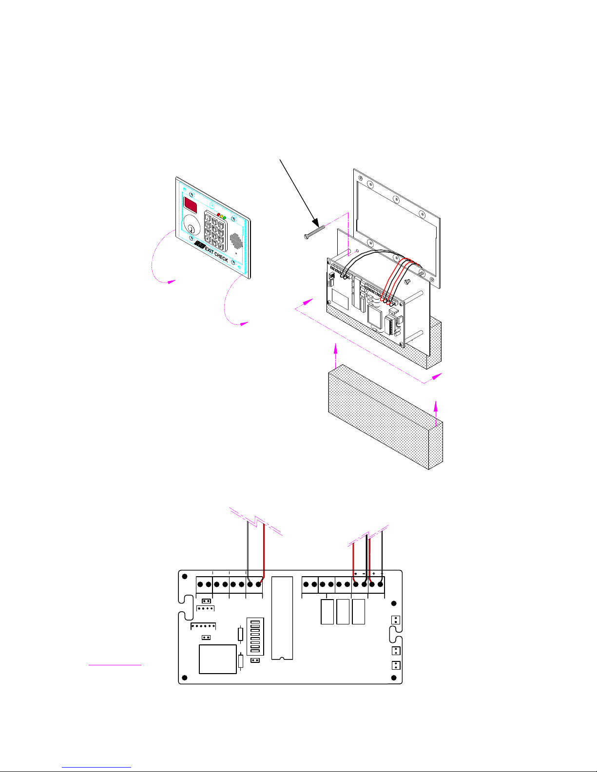
RECOMMENDED MOUNTING
PROCEDURE
USE 1-1/4” SCREWS SUPPLIED WITH
WALL MOUNT FRAME TO HANG UNIT
TEMPORARILY FOR WIRING PURPOSES
A
SLIDE PACKING FOAM BETWEEN WALL
AND UNIT TO PREVENT DAMAGE TO FACEPLATE
C NO C NO C NO C NO
J6
J4
REXTRIG RESET IBO
RESET
KEYPAD
C NCNOC NCNO
LOCK RED RLY GRN RLY
PWR
A
WIRE UNIT AS SHOWN
(SHOWN WITH NO OPTIONS).
VIEW A-A
P:\INSTALLATION INST\Delayed Egress\INST-101DE_KDE.vsd Rev D 09-14 Page 6
J1
SP1
Page 7
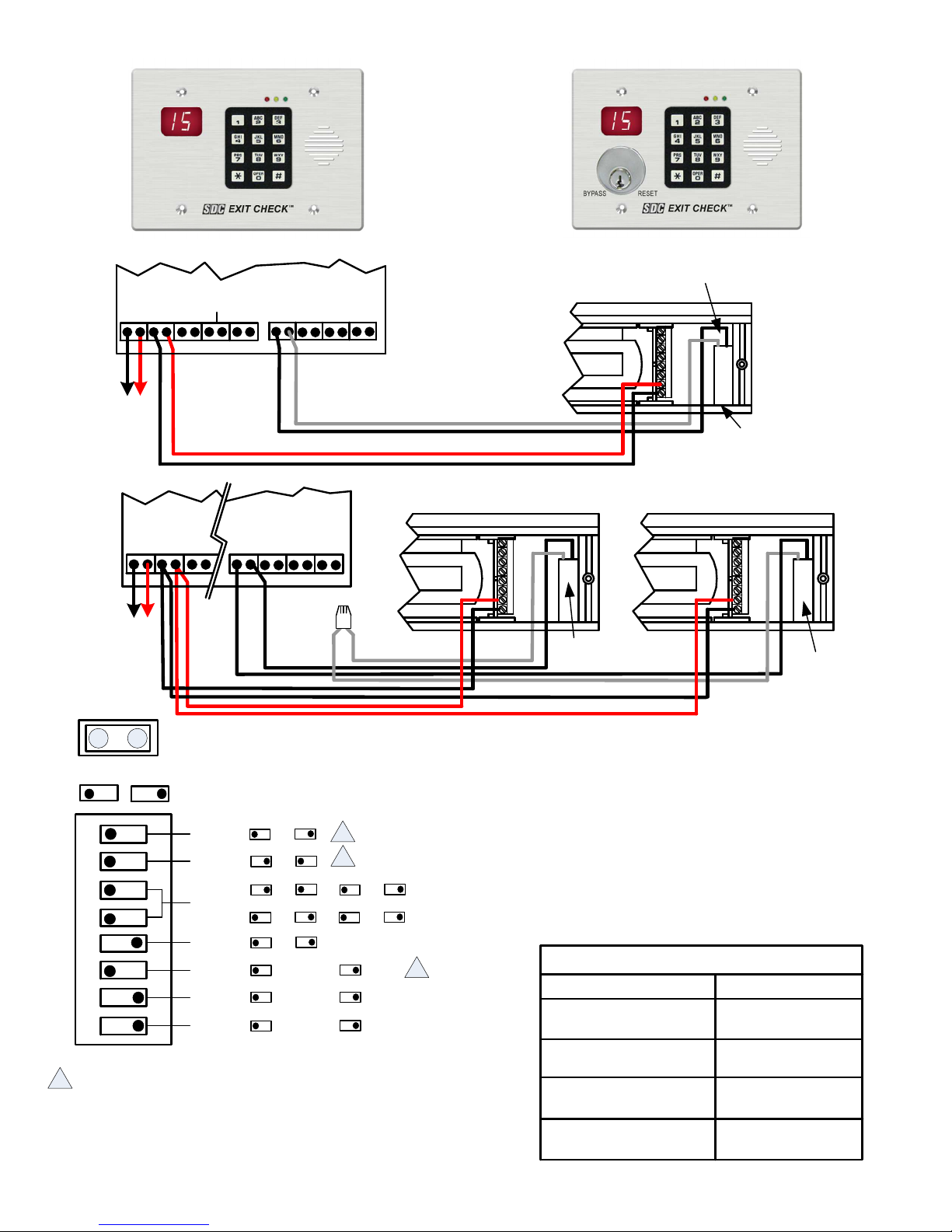
PWR
To
Power
Supply
MODEL 101-DE
101-DE / 101-KDE
RED RLY TRIG REX RESET
LOCK
- +- +
GRN RLY
NO C NCNO C NC
MODEL 101-KDE
Trigger
Switch
IBO
C NOC NOC NO
C NO
+ 3 4 5 6 7 8
-
SDC MODELS
1511DE 1575DE
1571DE 1576DE
1581DE
Note for 1581DE only:
Peel double sided tape on
trigger switch clip and stick
flush against end-block and
sidewall as shown.
101-DE
101-KDE
RESET
PWR LOCK RED R
NO C
TRIG REX
IBO
C NOC NOC NO- +- +
C NO
To
Power
Supply
JUMPER J1*
[OFF]
[ON]
DIP SWITCH
SETTINGS
1 2 3 4 5 6 7 8
WARNING!
*
CONTACT THE AUTHORITY HAVING JURISDICTION FOR APPROVAL
PRIOR TO SELECTING DELAY TIME OR PWR-UP SETTINGS
Functionality of the switches vary with the program option code. See Page 2
for a detailed description.
P:\INSTALLATION INST\Delayed Egress\INST-101DE_KDE.vsd Rev D 09-14 Page 7
ON
DELAY
TIME
NUISANCE
DELAY
REX/BYPASS
PERIOD
TRIGGER
TYPE
PWR UP
STATE
ALARM
TYPE
MESSAGE
15
30
*
2
1
15 20 30 1
UNLOCKED LOCKED
TONE
ONLY
FEMALE
MSG
*
N/CN/O
VOICE/TONE
MALE
MSG
*
+ 3 4 5 6 7 8
-
+ 3 4 5 6 7 8
-
l
Trigger
Switch
Trigger
Switch
PAIR OF
DOORS
*JUMPER J1 (DOOR PROP)
INSTALLED: The 101DE/KDE will enter the alarm mode if the
door is held open past the request to exit period.
REMOVED: The 101DE/KDE will remain unlocked if the door is
held open past the request to exit period. No alarm will sound.
The 101DE/KDE will relock and rearm upon closure of the door.
CONTROLLER SPECIFICATIONS
INPUT VOLTAGE 12 VDC OR 24 VDC
MAX CURRENT DRAW 180mA @ 12/24 VDC
(CONTROLLER ONLY)
MAX CURRENT 1 Amp @ 12/24 VDC
(LOCK OUTPUT)
MONITOR RELAYS 1 Amp @ 12/24 VDC
CONTACT RATING (RESISTIVE)
TEMPERATURE 0 C – 70 C
o o
Page 8
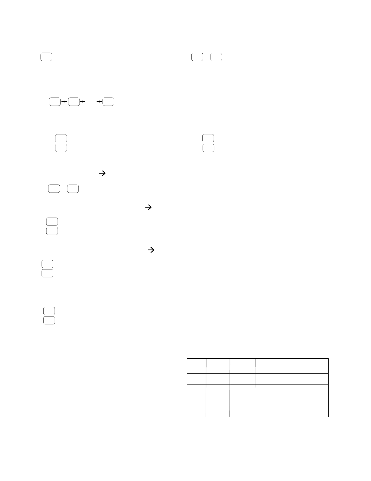
System Operation
POWER-UP UNLOCKED
The door is unlocked. To enter the
- -
Armed Mode, turn the keyswitch to
Reset or enter the Reset Code
“11 ” on the keypad
POWER-UP LOCKED
15
30
or
The door is
locked and
secure
*
DELAYED EGRESS MODE
15 14 01
...
The door is still locked and secure. The display is counting
down with audible alarm/voice instructions. Once the display
reaches “00”, the door will unlock.
ALARMED UNLOCKED [Alternating Display]
The door is unlocked and the alarm
00
is sounding. To return to Armed
Mode, close the door and turn the keyswitch
to Reset or enter the Reset Code “11 “
on the keypad
*
00
The door is unlocked and
has been opened
- -
- -
- -
RESET [Armed] Keypad Code 11 (Green LED solid)
*
15
30
or
AUTHORIZED EGRESS [REX] Keypad Code 22 (Green LED Solid)
The door is locked and secure
*
Door Closed
- -
- -
Door has
- -
- -
been opened
The door is unlocked until the REX timer has expired or
until the door has been opened and then closed.
BYPASS [Maintained Unlock] Keypad Code 33 (Green LED Flashing)
Door Closed
- -
Door has
- -
- -
- -
been opened
The door is unlocked indefinitely. To return to Armed Mode, enter the
Reset Code “11 “on the keypad.
*
*
KDE Model Only:
KEY SWITCH BYPASS [Maintained Unlock] (Green LED Solid)
Door Closed
- -
Door has
- -
- -
- -
been opened
The door is unlocked indefinitely. To return to Armed Mode, close the door and
turn the keyswitch to RESET or enter the Reset Code “11 “ on the keypad.
*
Keypad Programming
FACTORY PROGRAMMED CODES
Pin
User
No.
01
02
03
04
Code
1234
11
22
33 Bypass
*
*
*
*
Output
Code
NA
2
3
4
Master Code (default)
Reset
Authorized Exit (Rex)
GREEN
RED
YELLOW
KEYPAD STATUS LEDS
Steady :
Fast :
Flash
Steady :
Flash :
Slow :
Flash
Power on, No errors,
No outputs are active
No errors,
At least one output is active
General error, invalid code
entered
For ADA requirements, it will light
each time a key is pressed
Keypad is in Programming Mode
If the factory programmed codes are acceptable for your
installation, no additional programming is required.
Function
P:\INSTALLATION INST\Delayed Egress\INST-101DE_KDE.vsd Rev D 09-14 Page 8
Page 9
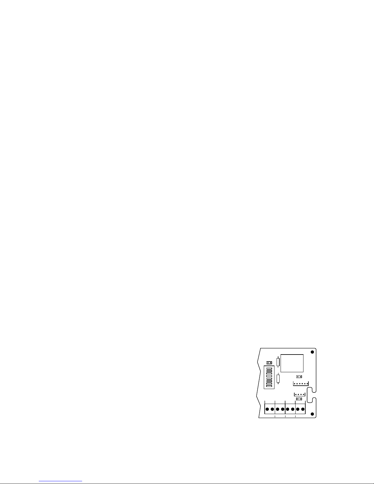
Changing the Master Code
User 1 is always used as the Master Code and is required to access keypad programming. The Factory
Default Master Code is “1234 ”. It is strongly recommended that a new Master Code is assigned after
installation. WRITE DOWN THE NEW CODE. If the master code is lost, you must use the keypad reset jumper
on the main circuit board to enter programming mode by using the Default Master Code.
To Change the Master Code (User 1)
1) Enter Programming Mode: Press 99# Master Code .
2) Assign new Master Code : Press 1# 01# New Pin Code# Output Relay # .
For example: 99# 1234 1# 01# 3871# 0# changes the Master code from 1234 to 3871.
3) Press to exit programming mode.
**
*
*
*
*
Entering Programming Mode
Press 99# Master Code .
For example: 99# 1234 Enters programming mode using the Default Master Code.
*
*
Adding a User / Changing User Pin Codes (Option 1)
To add a user:
Press 1# User Number (2 digits)# New Pin Code# Output Relay # .
For example: 1# 05# 55# 3# adds user 5's pin code as one that will activate authorized exit.
*
*
Deleting a User (Option 2)
To add a user:
Press 2# User Number (2 digits)# .
For example: 2# 05# deletes user 5.
*
*
Erase All Users (Option 8)
To ERASE ALL USERS!!
Press 8# .
All users are erased and the Default Master Code is reset to 1234.
*
Exit Programming Mode
Press .
**
Output Relay Codes
2= Reset
3= Authorized Exit
4= Bypass
Returning the Keypad to Factory Default Settings
Short the Keypad Reset [J4] jumper terminal located on the main controller board.
Press 99# 1234 8# .
Press 3#1#2# . Sets the Output #1 (Reset) for 2 seconds.
Press 3#2#2# . Sets the Output #2 (Auth Exit) for 2 seconds.
Press 3#3#0# . Sets the Output #3 (Bypass) for latching.
Press 1#02#11#2# . Adds user # 2 with a code of 11. [Reset]
Press 1#03#22#3# . Adds user # 3 with a code of 22. [Auth Exit]
Press 1#04#33#4# . Adds user # 4 with a code of 33. [Bypass]
Press to exit programming mode.
**
Remove the shorting jumper from the KP RST terminal.
P:\INSTALLATION INST\Delayed Egress\INST-101DE_KDE.vsd Rev D 09-14 Page 9
*
*
*
*
*
*
*
*
J1
REXTRIG RESET IBO
C NO C NO C NO
KEYPAD
RESET
J4
J6
C NO
Page 10
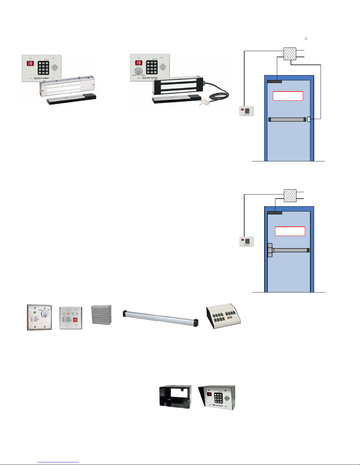
MODELS
101-DE
101-KDE
Door Without Latch Assembly
Activation By Sure Exit Push Bar
Power Supply
R
TO FIRE COMMAND
CENTER
115 VAC
1581DEV
1571DEV
1575DEU
1576DEU
1511DEV
DELAYED EGRESS CONTROLLER
101-DE Wall mount controller with keypad control and reset, 180mA @ 12/24 VDC.
101-KDE Wall mount controller with both keypad and key switch control and reset (less cylinder).
MAGNETIC LOCK WITH INTEGRATED ACTIVATION SENSOR
Specify 2 for pair of doors.
1511DEV Single, 1650 lbs. holding force, 670/350 mA @ 12/24 VDC, 628 std
1571DEV Single, 1200 lbs. holding force Energey Saver, 250/125 mA @ 12/24 VDC, 628 std
1581DEV Single, 650 lbs. holding force, 440/220 mA @ 12/24 VDC, 628 std
Outdoor Locks.
1575DEU Single outdoor magnetic lock with bond sensor, 630
1576DEU Single face drilled outdoor magnetic lock with bond sensor, 630
Lock Finish
Not available with outdoor lock
V 628 Clear Anodized Aluminum (Std) X Dark Bronze Power Coat (313/613 equal)
Y Black Anodized
Optional Outputs
B Magnetic Bond sensor, indicates locked with full holding force, low holding force,
unlocked, tampering and obstructions (1581DEV SPST only).
D Door position sensor, indicates door open and door closed. Commonly used to
verify egress after alarm and exit delay activation. Not available with 1581DE,
1576DE or 1575DE.
VI Spanish, or English and Spanish, or English and French verbal announcement.
VIC Custom verbal announcement (minimum 10 piece purchase).
PUSH UNTIL ALARM
SOUNDS. DOOR CAN BE
PUSH UNTIL ALARM
OPENED IN 15 SECONDS.
SOUNDS. DOOR CAN BE
OPENED IN 15 SECONDS.
MSB550/PSB560
REX Bar
Power Transfer
Hinge or Loop
Door With Latch Assembly
Activation By Door Movement
Power
Supply
PUSH UNTIL ALARM
SOUNDS. DOOR CAN BE
OPENED IN 15 SECONDS.
Standard Exit
Device
No switch
No Power Transfer
TO FIRE COMMAND
CENTER
115 VAC
ACCESSORIES
MSB550 Mechanical REX Exit bar for activation of locks on doors without latch assemblies.
PSB560 Sure Exit® REX sensor bar for activation of locks on doors without latch assemblies
101-SP External 15W speaker connects directly to 101-DE for enhanced decibels on site or
remote voice message annunciation.
101-4AM Four door station with LED’s and alarm tone for remote annunciation (indoor use).
TCC Desk top console for remote control and annunciation of 4 – 12 doors.
101-1AK Outdoor reset/bypass key switch with LED and Audible annunciator. 2-gang outdoor
box required. (Interior 101-DE and 1575DE or 1576DE outdoor magnetic lock required).
(Cylinder not included).
DEC-J 3-gang Interior surface mount box for 101-DE
1, 2 or 3 gang box mounted.
SHD-J Shroud for surface mount box DEC-J outdoor use
DEC-J required.
Only 101DE/KDE have been UL Listed as
Special Locking Arrangements to UL
standard 294 and NFPA 101.
P:\INSTALLATION INST\Delayed Egress\INST-101DE_KDE.vsd Rev D 09-14 Page 10
DEC-J
101-DE, DEC-J, SHD-J
SPECIFICATIONS
Inputs:
Voltage input: Auto sensing 12/24 VDC
Reset input: N/O, Dry
Rex input: N/O, Dry
Trigger: N/C or N/O, Dry
IBO input: N/O, Dry
Monitoring Outputs:
Alarm Output:
1 Amp @ 30VDC SPDT, dry
Locked Output:
1 Amp @ 30VDC SPDT, dry
Mechanical Specifications:
Controller: 6.5" x 4.5" x 1.5"
(165 x 114 x 38mm)
1581DE: 8.75" x 2.125" x 1.25"
(222 x 54 x 32mm)
1571DE/1511DE: 11" x 2.75" x 1.562"
(279 x 69.9 x 39.7mm)
1575DE/1576DE: 8.7" x 2.5" x 1.6"
(221 x 63.5 x 41mm)
Page 11
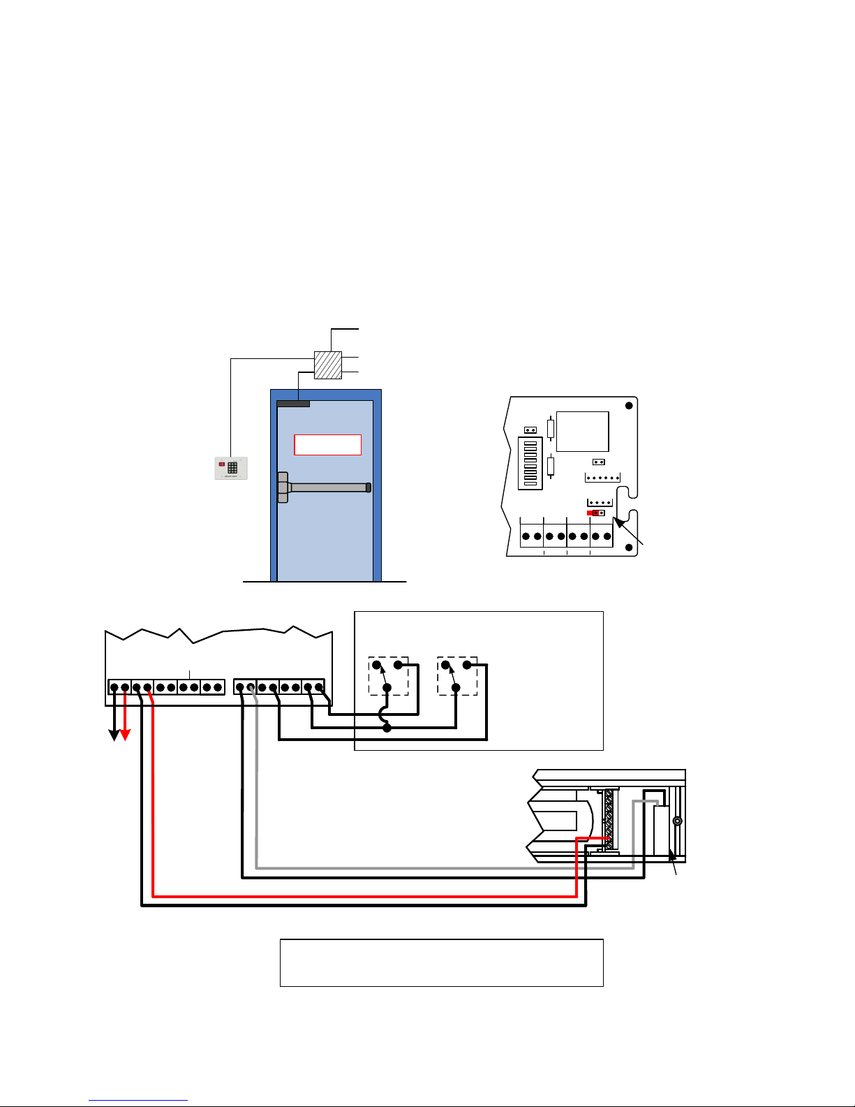
Connecting to a Infant/Patient Monitoring System
1. Locate jumper [J6] (above the IBO input). Verify that it is NOT installed across both pins.
2. Close AND hold the REX input. The 101-DE will be in Bypass Mode and will be unlocked.
3. Whenever the IBO input is closed AND held, the 101-DE will immediately relock and rearm.
Egress is possible by activating the Exit Check’s trigger input and initiating the irreversible 15 or 30 second
unlock cycle.
4. Releasing the IBO input will return the 101-DE to the Bypass Mode.
5. Releasing the REX input will rearm the system.
6. Upon power-up, you must manually reset the lock to activate the IBO input.
Door With Latch Assembly –
Activation By Door Movement
TO PATIENT MONITORING
Power
Supply
SYSTEM
TO FIRE COMMAND
CENTER
115 VAC
PWR
To
Regulated
Power
Supply
101-DE / 101-KDE
LOCK RED RLY
- +- +
GRN RLY
NO C NCNO C NC
TRIG REX RESET
C NOC NOC NO
PUSH UNTIL ALARM
SOUNDS. DOOR CAN BE
OPENED IN 15 SECONDS.
Standard Exit
Device
No switch
No Power Transfer
IBO
C NO
Close to
Override
Bypass
Close &
Hold to
Unlock
J1
KEYPAD
RESET
REXTRIG RESET IBO
C NO C NO C NO C N O
PATIENT
MONITORING
SYSTEM
J4
J6
Jumper must be removed.
+ 3 4 5 6 7 8
-
1511DE 1575DE
1571DE 1576DE
1581DE
P:\INSTALLATION INST\Delayed Egress\INST-101DE_KDE.vsd Rev D 09-14 Page 11
Trigger
Switch
Connection to a Infant/Patient Monitoring
System has not been investigated by UL.
Page 12
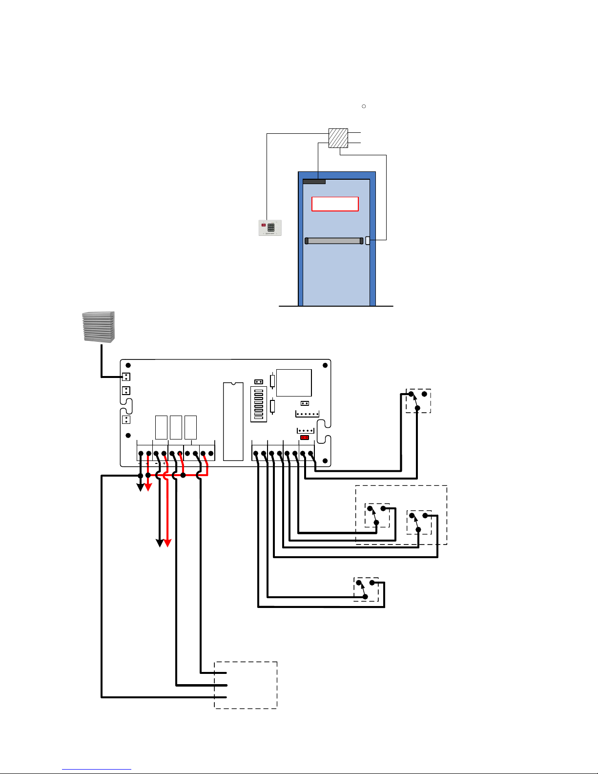
Connecting Optional Accessories
Remote Speaker
w/ plug-in
connector
101-SP
SP1
PWR
LOCK RED RLY GRN RLY
Door Without Latch Assembly
Activation By Sure Exit Push Bar
Power
Supply
PUSH UNTIL ALARM
SOUNDS. DOOR CAN BE
PUSH UNTIL ALARM
OPENED IN 15 SECONDS.
SOUNDS. DOOR CAN BE
OPENED IN 15 SECONDS.
MSB550/PSB560
REX Bar
J1
KEYPAD
J4
RESET
R
TO FIRE COMMAND
CENTER
115 VAC
Power Transfer
Hinge or Loop
EXTERNAL
DPS**
Door Contact required for
**
Anti-Tailgate and Door Prop
operation, when a remote
trigger device is used.
REXTRIG RESET I BO
J6
Jumper [J6] must be installed
across both pins.
C N CNOC NCNO
C NO C NO C NO C NO
Door Contact is shown with
the door closed.
To
Regulated
Power
Supply
Lock
Power
P:\INSTALLATION INST\Delayed Egress\INST-101DE_KDE.vsd Rev D 09-14 Page 12
REMOTE
ANNUCIATION
GRN LED (+)
RED LED (+)
LED COM (-)
101-1A or
101-1AK
REMOTE
RESET
REMOTE
TRIGGER
REMOTE
BYPASS
MSB550,
PSB560
101-1AK
 Loading...