

Page 1

USER INSTRUCTION GUIDE FOR
RECREATIONAL DIVING EQUIPMENT
(GROUPE - BREATHING - REGULATORS)
CONTENTS
1 Important regulations . . . . . . . . . . . . . . . . . . . . . . . . . . . . . . . . . . . . . . . . . . . . . . . . . . . . . . . . . . I-2
2 Terminology / Applications . . . . . . . . . . . . . . . . . . . . . . . . . . . . . . . . . . . . . . . . . . . . I-2
3 Technical safety regulations
. . . . . . . . . . . . . . . . . . . . . . . . . . . . . . . . . . . . . . . . . I-3
4 Model descriptions. . . . . . . . . . . . . . . . . . . . . . . . . . . . . . . . . . . . . . . . . . . . . . . . . . . . . . . . . . . . . . . . I-4
5 Technical descriptions
. . . . . . . . . . . . . . . . . . . . . . . . . . . . . . . . . . . . . . . . . . . . . . . . . . . . . . . . I-5
6 Technical specifications . . . . . . . . . . . . . . . . . . . . . . . . . . . . . . . . . . . . . . . . . . . . . . . . . . . I-20
7 Preparation for use
. . . . . . . . . . . . . . . . . . . . . . . . . . . . . . . . . . . . . . . . . . . . . . . . . . . . . . . . . . . . . . I-21
8 Use of the equipment . . . . . . . . . . . . . . . . . . . . . . . . . . . . . . . . . . . . . . . . . . . . . . . . . . . . . . . . I-22
9 Procedures after use. . . . . . . . . . . . . . . . . . . . . . . . . . . . . . . . . . . . . . . . . . . . . . . . . . . . . . . . . . . I-23
10 Care and attention . . . . . . . . . . . . . . . . . . . . . . . . . . . . . . . . . . . . . . . . . . . . . . . . . . . . . . . . . . . . . . . I-23
11 Maintenance
. . . . . . . . . . . . . . . . . . . . . . . . . . . . . . . . . . . . . . . . . . . . . . . . . . . . . . . . . . . . . . . . . . . . . . . . . . . . . I-25
12 Inspection. . . . . . . . . . . . . . . . . . . . . . . . . . . . . . . . . . . . . . . . . . . . . . . . . . . . . . . . . . . . . . . . . . . . . . . . . . . . . . . . . . . . . I-25
13 Troubleshooting
. . . . . . . . . . . . . . . . . . . . . . . . . . . . . . . . . . . . . . . . . . . . . . . . . . . . . . . . . . . . . . . . . . . . . . I-25
14 Additional combinations. . . . . . . . . . . . . . . . . . . . . . . . . . . . . . . . . . . . . . . . . . . . . . . . . . . . I-26
15 Accessories
. . . . . . . . . . . . . . . . . . . . . . . . . . . . . . . . . . . . . . . . . . . . . . . . . . . . . . . . . . . . . . . . . . . . . . . . . . . . . . I-26
I - 1
ENGLISH
Page 2

1. IMPORTANT REGULATIONS
WARNING: SCUBA complying with EN 250 are not intended for more than one
user to breath at the same time.
If the SCUBA are used by more than one diver at the same time, then the cold
water and breathing performance may not fulfil the requirements of EN 250.
For your protection while using SCUBAPRO
®
life support equipment, we call your
attention to the following:
a. Any use of the equipment is conditional to reading, understanding, and following
this user instruction guide.
b. Use of the equipment is limited to those applications described in this guide and
for purposes granted in writing from SCUBAPRO
®
.
c. The equipment must be serviced annually (e.g. examined, serviced, and if
required, repaired) by an authorized SCUBAPRO
®
repair technician. This
maintenance must be documented (we suggest our SCUBAPRO
®
Log/Service
Book). Only original SCUBAPRO
®
parts may be used for maintenance and repair.
d. If the equipment is improperly serviced, or repaired by persons not trained by
SCUBAPRO
®
, and in cases where the equipment is used for purposes not
specifically designated; liability for the correct and safe function of the equipment
transfers to the owner/user.
e. instructions and statements contained in this document are based on the latest
information available prior to printing. SCUBAPRO
®
reserves the right to make
changes at any time.
f. Local statutes and regulations must be followed when transporting this equipment.
2. TERMINOLOGY / APPLICATIONS
SCUBAPRO®recreational diving equipment includes: self-contained, open circuit
compressed air underwater breathing apparatus (i.e. SCUBA). SCUBA equipment
allows a diver to breathe underwater by carrying a portable supply of regulated
compressed air with him underwater.
The purpose of a breathing regulator system is to reduce the pressure of the
compressed air in the cylinder and supply breathable air to the diver upon demand.
The system also provides outlets for underwater pressure gauges and intermediate
pressure hoses for inflation of buoyancy control devices, dive suits, etc...
NOTE: FOR SIMPLICITY, PRESSURE REGULATORS AND DEMAND VALVES ARE
REFERRED TO AS “1st STAGE” AND “2nd STAGE” REGULATORS,
RESPECTIVELY, THROUGHOUT THE REST OF THIS DOCUMENT.
A breathing regulator system consists of: a first stage regulator coupled with one or
more second stage regulators which have depth limitations. Any individual diving
activitiy is limited by the experience and condition of the individual diver. SCUBA
should not be used deeper than 50 meters (130 ft).
EN250:2000 regulates the minimum requirements for recreational SCUBA equipment
in Europe. SCUBAPRO
®
equipment conforms to EN250:2000.
User Instructions for Breathing Regulators
I - 2
Page 3

EN250:2000 requires that the minimum SCUBA unit consist of the following elements:
• Compressed air cylinder(s) conforming to national regulations of the
corresponding European Standard.
• Breathing regulator: consisting of a first and second stage regulator set.
• Face mask and mouthpiece, full face mask, or diving helmet.
•
Frame or holding device for air cylinder(s) with the possibility to mount the harness.
• Carrying system.
• Safety system, including at least one of the following:
a. submersible pressure gauge,
b. reserve valve,
c. active low pressure warning device.
• Instructions for use must be included.
3. TECHNICAL SAFETY REGULATIONS
The recommendations and advice of a recognized recreational diving instructional
agency should be followed on every dive. Before participating in any diving activity,
a thorough course of instruction in the theory and practices involved in diving
should be successfully completed.
This user instruction guide does not replace a complete course of diving instruction!
Prospective diving students should undergo and pass a diving medical
examination prior to commencing instruction. Active divers should be re-examined
as required by their physician.
Air cylinders should by filled with quality compressed air only (in accordance with
EN 12021). Poor quality air can cause corrosion to form in the cylinder as well as
lead to regulator system icing and malfunction in low temperature environments.
When transporting high pressure cylinder(s), national and local regulations for the
transportation of dangerous goods (GGVS) should be observed. Regulations for
using air cylinders is covered in the “use and handling of gasses” (TRG 402, para
4 and 5) and is described in other governmental regulations.
Cold water diving regulator:
SCUBA systems intended for use in temperatures below 10°C (50° F) must employ
regulator sets proven for cold water diving.
Required safety devices:
In addition to those requirements detailed in “2 Terminology / Applications” SCUBA
sets intended for use in certain exceptional operations conditions must meet
additional criteria.
• Whenever the amount of air remaining must be known (e.g. cave, cavern,
wreck, current, or ice diving) a submersible pressure gauge (spg) is required.
• Whenever the use of a spg is difficult or impossible (e.g. Iow visibility) a reserve
valve or active warning device is required.
I - 3
User Instructions for Breathing Regulators
ENGLISH
Page 4
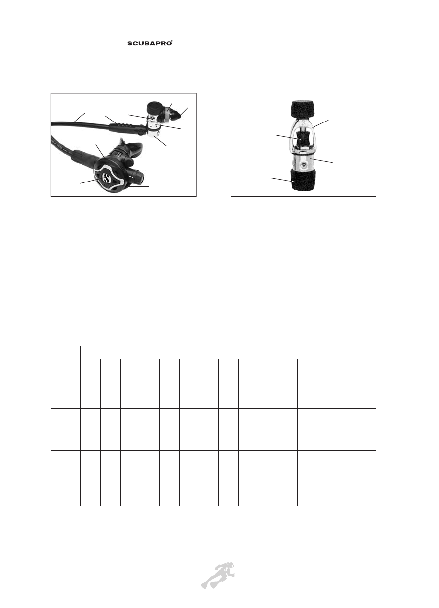
4. MODEL DESCRIPTIONS
a. 1st Stage MK25 a. 1st Stage MK2 Plus
b. din retaining shaft with knurled retaining wheel b. Retaining yoke and screw (Yoke
c. Low pressure swivel ports system)
d. High pressure port c. Protective cap
e. Inlet protector DIN / INT d. Inlet protector
f. 2nd Stage S600
g. Purge button
h. Bubble deflector
I. Protective hose sleeve
j. Low pressure hose
4.1 Authorized SCUBAPRO®regulator “set”.
(some combinations may not be available in all countries).
SCUBAPRO®2nd stage octopus are provided standard with:
• a yellow cover,
• a 100 cm low pressure hose, and
• an octopus holder.
User Instructions for Breathing Regulators
I - 4
e
b
a
c
f
g
j
h
i
d
fig. 1 : MK25 DIN / S600
fig. 2 : MK2 Plus INT
b
a
d
c
2nd Stages
MK2 Plus
XXXX XX
INT/DIN
MK17 A.F.
X XXXX XXXX XXX
INT/DIN
MK16
X XXXX
INT/DIN
MK18
X XXXXXXXX
INT/DIN
MK25 A.F.
X XXXXXXXXX XXX
INT/DIN
MK20
X
NITROX
MK25T
XXX XXXX X X X X
INT/DIN
MK25 SA
XXX XXXX X X X X
INT/DIN
MK11
XXXXX
INT/DIN
1st Stages
X650T X650 S600T
S600/
CLASSIC
S600 S550
G250
HP
D400
R290/
R380/
R390
R290/
R380/
R390
OCTOPUS
R190
R190
OCTOPUS
S555
R295/
R395
R295/
R395
OCTOPUS
Page 5

I - 5
5. TECHNICAL DESCRIPTIONS
High quality material and engineering used in the manufacture of SCUBAPRO
®
regulators insure maximum reliability and safety. SCUBAPRO®has been building
high quality diving equipment for over 35 years. All SCUBAPRO
®
regulator systems
consist of two stages. The 2nd stage is a negative pressure activated, breathing
controlled demand regulator. The 1st stage, connected to the cylinder valve, is
intended to reduce the high pressure air supply (200-300 bar) down to an
intermediate pressure of 9.5 bar (135 psi) over ambient pressure. The regulated
pressure air is supplied to the 2nd stage via a low pressure hose.
5.1
A.F. and T.I.S. (ANTIFREEZE MK25’s and THERMO
INSULATING SYSTEM) (EU/USA patents)
The above two systems for first stages regulator have to be installed by a qualified
SCUBAPRO®service technician.
They have been designed to provide resistance to freezing in accordance with
European Norms (EN250:2000) for cold water performance at < 10°C (50°F) (ref.
section 5.11.3).
5.2 Thread or Yoke Connections
SCUBAPRO®first stage regulators are currently available with either of two
different cylinder valve connections :
• Threaded : this connector uses a knurled and threaded retaining wheel and
complies with ISO 12209-2 (200 or 300 bar).
• Yoke : this international connector consists of a yoke and knob type fixing screw
for use in systems up to 230 bar and complies with ISO 12209-1.
Cylinder connections can be exchanged by an authorized SCUBAPRO
®
repair
technician.
5.3 Conical sintered filter
The conical sintered filter has a 300% larger surface area than disc shaped filters.
The filter traps rust and other large particles before their entering into the 1st stage
regulator.
5.4 H.P. cave cone seat
Designed and patented by SCUBAPRO®, the cave cone seat in the balanced piston
first stages eliminates the annoying “whistling” common with other piston type 1st
stages. (EU patent Nr 0.310.738).
5.5 Down-stream system
“Down-stream” describes a valve that opens with air flow. With a down-stream
system, the delivery valve in the 2nd stage opens automatically (like a safety valve)
if the intermediate pressure supplied by the 1st stage increases above expected
User Instructions for Breathing Regulators
ENGLISH
Page 6

pressures. This approach insures that air is supplied to the diver should the 1st stage
malfunctions and offers considerably lower inhalation resistance compared to an
“up-stream” configuration.
5.6 Intermediate pressure hose
In 1983 SCUBAPRO®developed an intermediate pressure “SuperFlow” hose that has
a 33% higher air flow capacity for the same external diameter. The SuperFlow hose
fits all SCUBAPRO®regulators, including those manufactured before 1983.
5.7 Mouthpiece
The orthodontic mouthpiece is designed to fit perfectly in the mouth and adapt to teeth
and gums achieving maximum comfort whilst securing the second stage firmly in place.
5.8 Full face mask
Any SCUBAPRO®2nd stage regulator, minus the mouthpiece, can be fitted to the
SCUBAPRO®full face mask (p/n 24.150.000) by an authorized SCUBAPRO®repair technician.
5.9 Registration
All SCUBAPRO®regulators are marked with a serial number (s/n). On the metal 2nd
stages, the s/n can be found on the rear surface above the bubble deflector. On most
plastic 2nd stage regulators, the s/n may be found on the rear face of the bubble
deflector or on the mouthpiece surface. The D400 has the s/n on the side of the body.
All 1st stage regulators display the s/n on the main body.
5.10 Silicone
The diaphragm and air exhaust valve are manufactured from fine, highly sensitive
silicone material. This extremely flexible material reduces the effort required for
breathing during both inhalation and exhalation.
5.11 Compatibility
Reverse compatibility; a company philosophy. New components are designed to be
compatible with older versions of similar models. Even an old MK5 1st stage can be
brought up to date with the latest components.
5.12 Worldwide Lifetime Guarantee
SCUBAPRO®offers the original owner of all new breathing regulators a lifetime guarantee
covering material and manufacturing defects for all components except mouthpieces and
intermediate pressure hoses. Documented annual service and inspection by an
authorized SCUBAPRO
®
repair technician is mandatory to maintain this Guarantee.
5.13 EN250:2000 Approval
All SCUBAPRO®regulators exceed the strict requirements required by the European
Standard EN250:2000. When fitted with a T.I.S./A.F. (antifreeze) kit, all SCUBAPRO
®
1st stage regulators conform to the requirements for cold water conditions.
User Instructions for Breathing Regulators
I - 6
Page 7
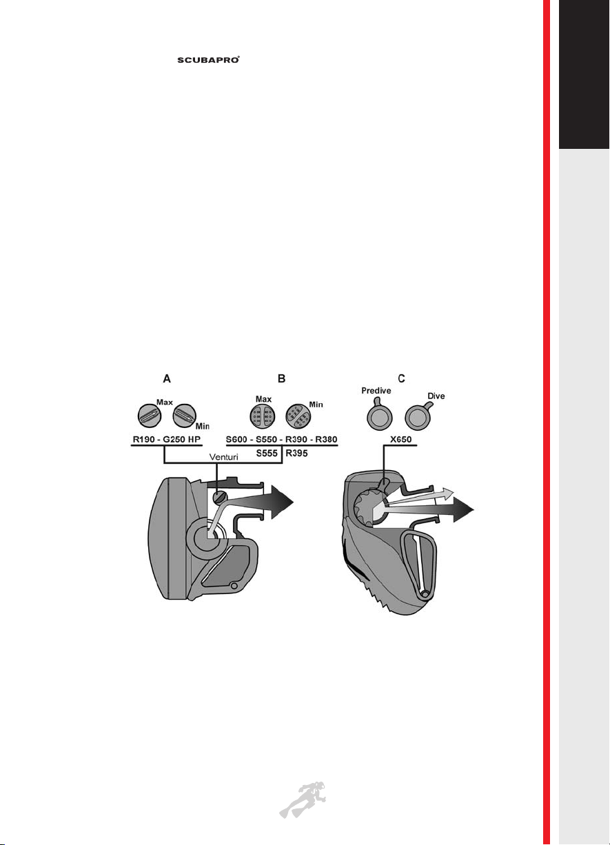
5.14 V.l.V.A. (Venturi lnitiated Vacuum Assist)
Many SCUBAPRO®regulators are equipped with a diver-controlled V.I.V.A. Others have
an internal V.I.V.A. or one that can be adjusted by an authorized SCUBAPRO®technician.
V.l.V.A. (US Patent 4,796,618) allows the diver to finely control the inhaled air
stream. This is possible by situating a flow vane in the mouth piece orifice. The
angle of the vane controls the flow of air into the divers mouth. Adjusting the V.l.V.A.
control lever on the outside of the 2nd stage can maximize the venturi effect of the
breathing air stream. High speed air flowing over the vane produces a low pressure
area behind it, pulling the diaphragm in and depressing the valve actuating lever
and opening the inlet valve.
Adjusting the Venturi effect (fig. 3):
•
Turn the lever to the MIN/PREDIVE position when entering water, during buddy breathing,
or when using the 2nd stage as an alternative air source (Octopus)
or when descending head-first.
•
Turn the lever to the MAX/DIVE position to achieve maximum air flow, during dive.
5.15 1st Stage MK2 Plus (Standard Piston) T.I.S.
Simplicity, reliability, and minimum servicing effort are the halimarks of the MK2 1st
stage regulator. Being manufactured since 1963, it contains only one moving part:
the piston. The small size and low weight are the major advantages of the MK2, yet
it still offers four intermediate pressure ports and one high pressure port. It is T.I.S.
compatible for cold water diving.
Note: Designed for the maximum resistance to most conditions, a minimum of care
and maintenance is recommended (see point 10. CARE AND ATTENTION).
I - 7
User Instructions for Breathing Regulators
fig. 3
ENGLISH
Page 8

5.16 1st Stage MK25T (Titanium) (Balanced) A.F./T.I.S.
As for many other diving products, SCUBAPRO®had always been at the forefront of
technology and materials. It was the first ever, for example, to introduce a first stage
regulator fully made out of titanium as far back as 1988. This new model is thus the
evolution of this brought to perfection, in which new technologies and ideas have been
applied to the already legendary MK20 (now MK25).
Titanium is a very unique material, which weighs half as much as brass (typical material
used for first stage manufacturing) yet has superior mechanical and electrochemical
properties. The latter allow the preformance and cosmetic appearance of the product to
remain unchanged over time. In addition to the already exceptional performance
characteristics of the base project, these are the new model features:
- T.l.S. (Thermal Insulating System) (EU/USA patent)
It consists of a soft and rigid sleeve combination around the 1st stage stainless steel
piston to insulate the very cold through air flow from the water around, to prevent ice
formation around the spring which is coated (fig. 4). The ice-breakers on the rigid
bushing interrupt the ice formation, which tends to break off upon forming (patents no.
EU 0.811.549 – no. USA 5.775.368)
T.I.S. 2 version: a second soft sleeve has been added over the 1st one, to further
improve the thermal insulation of the piston.
- Composite Piston (C.P.) (Pat. pend.)
(low pressure side made of technopolymer with double o-ring, HP shaft of stainless
steel)(fig. 4). This solution improves the above T.I.S. function, to insulate air flow
passing from the water around, especially where the air expands at most (inside the
low pressure piston head) : the combination of the two solutions (C.P. and T.I.S.)
allows to get the highest flow rate of any first stage (almost 10.000 l/min) with an
extreme cold water resistance, thanks also to the new antifreeze cap (see below).
- Antifreeze Cap (A.F.) (pat. pending)
Its external ribs (fig. 5) almost make double the external thermal exchange surface in
contact with water, still further delaying the ice formation, even below the EN 250:2000
cold test limit (2°C).
- Rapid Intermediate Pressure Adjustment (pat.) (to be performed by Authorized
Scubapro Technicians only) : the intermediate pressure can now be adjusted
externally, and needn’t disassemble the first stage. An adjustment screw made out of
stainless steel (to avoid gripping between titanium parts) moves the high pressure
seat axially. Rotation is hampered by an antifriction spacer.
Given the superior mechanical resistance and imperviousness to all chemical and
electrochemical agents of the materials employed, maintenance is reduced to a
minimum and limited to only the sealing elements (o-rings, gaskets, seats, etc.)(refer
to section 10, Care and Maintenance).
User Instructions for Breathing Regulators
I - 8
Page 9

5.17 1st Stage MK25 - S.A. (Stainless Steel - Alloy)
(Balanced) A.F./T.I.S.
This version is the natural evolution of our UltraLight line, to which we have added
new features and functions that eliminate the minimal usage defects encountered
there, still keeping the minimum weight.
It is a composite material regulator, which utilizes the optimum material for each
function and location.
All “static” components (cap, main body, etc.) are made out of a special aluminum
alloy, anodized (refer to section 5.21).The other components, subjected during use
to harsher conditions and/or dynamic loading and friction (swivel, yoke retainer,
yoke screw, etc.) are made out of stainless steel. The latter are perfectly compatible
with the alloy since they preserve, over time, their technical and esthetic properties
: in order to prevent the alloy body in direct contact with the brass of the hose
fitting, on one of the two HP ports, there is a stainless steel adapter to fit the said
HP hose.
In addition to the absolute low weight, the nice esthetics and to the already
exceptional performance characteristics of the MK20 (now MK25), this new model
features new and innovative technical solutions:
- T.l.S. (Thermal Insulating System) (EU/USA patent)
It consists of a soft and rigid sleeve combination around the 1st stage stainless
steel piston to insulate the very cold through air flow from the water around, to
prevent ice formation around the spring which is coated (fig. 4). The ice-breakers
on the rigid bushing interrupt the ice formation, which tends to break off upon
forming (patents no. EU 0.811.549 – no. USA 5.775.368)
T.I.S. 2 version: a second soft sleeve has been added over the 1st one, to further
improve the thermal insulation of the piston.
- Composite Piston (C.P.) (Pat. pend.)
(low pressure side made of technopolymer with double o-ring, HP shaft of stainless
steel)(fig. 4). This solution improves the above T.I.S. function, to insulate air flow
passing from the water around, especially where the air expands at most (inside
the low pressure piston head) : the combination of the two solutions (C.P. and
T.I.S.) allows to get the highest flow rate of any first stage (almost 10.000 l/min) with
an extreme cold water resistance, thanks also to the new antifreeze cap (see
below).
- Antifreeze Cap (A.F.) (pat. pending)
Its external ribs (fig. 5) almost make double the external thermal exchange surface
in contact with water, still further delaying the ice formation, even below the EN
250/2000 cold test limit (2°C).
- Rapid Intermediate Pressure Adjustment (pat.) (to be performed by Authorized
SCUBAPRO
®
Technicians only) : the intermediate pressure can now be adjusted
externally, and needn’t disassemble the first stage. An adjustment screw made out
of stainless steel (to avoid gripping between titanium parts) moves the high
pressure seat axially. Rotation is hampered by an antifriction spacer.
I - 9
User Instructions for Breathing Regulators
ENGLISH
Page 10

Given the superior mechanical resistance and imperviousness to all chemical and
electrochemical agents of the materials employed, maintenance is reduced to a
minimum and limited to only the sealing elements (o-rings, gaskets, seats, etc.)(refer
to section 10, Care and Maintenance)
User Instructions for Breathing Regulators
I - 10
fig. 4
fig. 5
T.I.S. AND COMPOSITE PISTON (C.P.)
RIGID THERMOINSULATING
SLEEVE W/ICE-BREAKER RIBS
HP AIRL.P. AIR
SOFT SLEEVE T.I.S. 2
STAINLESS STEEL
PISTON SHAFT (C.P.)
TECHNOPOLYMER
PISTON HEAD (C.P.)
THERMOINSULATED
SPRING (COATED) (T.I.S.)
SOFT SLEEVE T.I.S.
Page 11

5.18 1stStage MK25 (Balanced) A.F./T.I.S.
The MK25 1ststage comes straight from the legendary MK20, to which latest new
concepts and technologies have been applied :
- T.l.S. (Thermal Insulating System) (EU/USA patent)
It consists of a soft and rigid sleeve combination around the 1st stage stainless
steel piston to insulate the very cold through air flow from the water around, to
prevent ice formation around the spring which is coated (fig. 4). The ice-breakers
on the rigid bushing interrupt the ice formation, which tends to break off upon
forming (patents no. EU 0.811.549 – no. USA 5.775.368)
T.I.S. 2 version: a second soft sleeve has been added over the 1st one, to further
improve the thermal insulation of the piston.
- Composite Piston (C.P.) (Pat. pend.)
(low pressure side made of technopolymer with double o-ring, HP shaft of stainless
steel)(fig. 4). This solution improves the above T.I.S. function, to insulate air flow
passing from the water around, especially where the air expands at most (inside
the low pressure piston head) : the combination of the two solutions (C.P. and
T.I.S.) allows to get the highest flow rate of any first stage (almost 10.000 l/min) with
an extreme cold water resistance, thanks also to the new antifreeze cap (see
below).
- Antifreeze Cap (A.F.) (pat. pending)
Its external ribs (fig. 5) almost make double the external thermal exchange surface
in contact with water, still further delaying the ice formation, even below the EN
250:2000 cold test limit (2°C).
- Rapid Intermediate Pressure Adjustment (pat.) (to be performed by an
Authorized SCUBAPRO
®
Technicians only) : the intermediate pressure can now be
adjusted externally, and needn’t disassemble the first stage. An adjustment screw
made out of stainless steel moves the high pressure seat axially. Rotation is
hampered by an antifriction spacer.
The remarkably stable intermediate pressure and higher flow of air produced by the
MK25 stems from the piston construction. The pneumatically balanced air flow
through the piston, a development pioneered by SCUBAPRO
®
in the 60’s, remains
unaffected by changes in cylinder pressure.The high pressure air from the cylinder
acts radially around the piston stem without exerting a moving force. The force used
to move the piston and close the valve is generated by the fluctuating pressure
working against the main spring.
The consistent air flow rate is principally due to the construction details . Most 1st
stage regulators are designed for maximum performance with a full cylinder. The
MK25 design was conceived to insure maximal performance with lower supply
pressures as well. Small bores were increased to allow higher air flow at lower
pressures. The piston diameter was increased and its stem length adjusted to
maximize available flow to the 2nd stage, increasing overall performance.
Intermediate pressure ports are situated on a swivel turret allowing 360° rotation
even while pressurized. The swivel has 5 intermediate pressure ports: 4 situated
I - 11
User Instructions for Breathing Regulators
ENGLISH
Page 12

radially from the flow, and one at top dead center. The center port offers 15% greater
air flow than the radially situated ports. High pressure outlets are found on each side of
the main body, permitting an spg and/or console to be connected on either the right or
leflt side.
Note: Designed for the maximum resistance to most conditions, a minimum of care
and maintenance is recommended (see point 10. CARE AND ATTENTION).
5.19 Diaphragm 1st stages: MK17 A.F. and MK11
In a diaphragm first stage, water pressure is transmitted to the H.P. valve by a
flexible membrane that seals the internal HP mechanism; this is the best solution
when diving in dirty or cloudy or contaminated water. High quality of materials and
innovative engineering solutions used in the manufacture of MK17 /MK11 provide
maximal performance and reliability.
The MK17 is an over balanced first stage with design and performances
characteristic of the SCUBAPRO® family:
1. The small size and low weight are the major advantages of the MK17, yet is still
offers four intermediate pressure ports and two high pressure ports.
2. It is a balanced first stage, with a built in antifreeze system.
3. Replaceable HP seat and HP poppet for durability and easy servicing.
4. Two special LP ports (HFP), close to the diaphragm, offer ~15% greater air flow.
5. The Dry balance chamber prevents the water contact with the diaphragm and the
spring, the regulator then achieves the best cold water performances.
The MK11 is a 1st stage with all of MK17 functional characteristics, but it is lighter
and smaller because of the absence of the dry balance chamber.
Note: Designed for the maximum resistance to most conditions, a minimum of care
and maintenance is recommended (see point 10: CARE AND ATTENTION).
5.20 2nd Stage R190
This is the most popular standard regulator in the world. The case made of fiberglass
and graphite reinforced polyamide guarantees low weight, high resistance to wear,
and superb breathing comfort. It can be configured for an intermediate pressure hose
connection on the right or on the left for use as an alternate air source (octopus).
The V.l.V.A. can be adjusted both in and out of the water (see point 5.14 V.l.V.A. - fig.3).
A decrease in breathing assistance can be an advantage when entering the water,
descending head first, in strong currents, or to prevent unwanted “Free flow” when
using the second stage as an octopus. It is provided with an antiengraving system
(see point 10. CARE AND ATTENTION, Storage - fig.11).
Use and maintenance ( see point 8-9-10-11 on the manual).
User Instructions for Breathing Regulators
I - 12
Page 13

5.21 2nd Stage R290
This second stage is the R190’s natural evolution which is the most popular
regulator in the world.
Lightweight (150 g. only) and reduced size (25% smaller) are the two remarkable
improvements of this unit, still maintaining, or rather, optimizing all the R190’s features.
The R290 can be assembled with the L.P. hose either on the right or on the left
side.
The R290 has a preset moderate Venturi effect which prevents the unwanted free
flow: it can be adjusted by an Authorized Scubapro repair technician to the
personal requirement of the diver.
Use and maintenance (see point 8-9-10-11 on the manual).
5.22 2nd Stage R295
This second stage is the R290’s natural evolution.
The main innovations are the greater performances due to the new lever and the
new diaphragm with the new disc that allows a lower friction.
The new shape of the lever offers a more progressive and constant air flow.
The R295 can be assembled with the LP hose either on the right or on the left side.
The R295 has a preset moderate Venturi effect which prevents the unwanted free
flow: it can be adjusted by an Authorized Scubapro repair technician to the
personal requirement of the diver.
Use and maintenance (see point 8-9-10-11 on the manual).
5.23 2nd Stage R390
This second stage is the R190's natural evolution which is the most popular
regulator in the world for maximum reliability and performances.
Lightweight (150 g. only) and reduced size (25% smaller) are the two remarkable
improvements of this unit, still maintaining, or rather, optimizing all the R190's features.
The R390 can be assembled with the L.P. hose either on the right or on the left
side.
The R390 allows to personalize the Venturi effect, by simply adjusting a lever
(fig. 3 - see point 5.14 V.l.V.A.). A decrease in breathing assistance can be an
advantage when entering the water or when descending head first.
Use and maintenance ( see point 8-9-10-11 on the manual).
5.24 2nd Stage R395
This second stage is the R390’s natural evolution.
The main innovations are the greater performances due to the new lever and the
new diaphragm with the new disc that allows a lower friction.
The new shape of the lever offers a more progressive and constant air flow.
The R395 can be assembled with the LP hose either on the right or on the left side.
I - 13
User Instructions for Breathing Regulators
ENGLISH
Page 14

The R395 allows to personalize the Venturi effect, by simply adjusting a lever (fig 3 –
see point 5.14 V.I.V.A.). A decrease in breathing assistance can be an advantage
when entering the water or when descending head first.
Use and maintenance (see point 8-9-10-11 on the manual).
5.25 2nd stage S600 / CLASSIC /S600T
In this model, all SCUBAPRO® features developed from many years of experience
have been concentrated in order to offer the best comfort, performances and
durability, in a pleasant design.
Lightweight, reduced size, anti-icing system, orthodontic mouthpiece, are some key
aspects of this project as well as the inhalation and vacuum assist control (V.I.V.A.),
the pneumatically balanced poppet and a new design.
- Weight: S600/CLASSIC= 168g.; S600T =152g. These are the SCUBAPRO®
lightest second stages, thanks to the use of carbon fibre and TITANIUM (with the
S600T).
- Pneumatically balanced: pneumatic balancing is made possible by a small
longitudinal bore hole through the seat and poppet assembly. This allows air to pass
into a small chamber at the far end of the piston. The air trapped chamber provides a
counter force moving the piston back against the intermediate pressure port,
balancing out the forces trying to open the valve. This permits the use of a softer
spring and provides a smoother action under all conditions.
WARNING: during storage, unscrew the adjustment knob to reduce engraving
of the poppet (+) (fig 6D).
- Full anti-icing system: the composite housing, made of metal and technopolimer
with carbon fibers added, insulates and protects the valve-lever assy, giving the
S600/S600T a superior performance under extreme cold conditions, by virtually
eliminating the ice formation in the second stage (Patented) (fig 6 – B).
- Lever: the shape of the lever (fig 6 – L) allows a smoother progression of the flow
during inhalation.
- Orthodontic mouthpiece: designed in cooperation with worldwide experts in this
matter, it offers the best grip with the lowest jaws effort, as well as better breathing
performance.
- Poppet: streamlined and light for better flow feature with a low friction, and
consequently a low inhalation resistance
- Inhalation resistance control: the inhalation resistance can be adjusted on the
S600/S600T by turning the external knob (fig 6 D).
The screw adjusts the valve spring tension which leads to a corresponding increase
or decrease in the inhalation resistance. The knob must be turned clockwise inward,
to increase the inhalation resistance and counterclockwise (outward) to decrease the
inhalation resistance. These adjustments can be made both in and out of the water. A
decrease in breathing assistance can be advantageous when entering the water,
User Instructions for Breathing Regulators
I - 14
Page 15

descending head first, in strong currents, or to prevent unwanted “free flow” when
using the second stage as an octopus.
- V.I.V.A. (see fig. 3 B – point 5.14 on the manual)
Note: Hard breathing settings will not help you conserve air, and may actually have
the opposite effect because of increased respiratory fatigue.
Use and maintenance (see point 8-9-10-11 on the regulator manual)
I - 15
User Instructions for Breathing Regulators
fig. 6
ENGLISH
Page 16

5.26 2nd stage S550
Lightweight, reduced size, anti-icing system, orthodontic mouthpiece, are some key
aspects of this project as well as the inhalation and vacuum assist control (V.I.V.A.) and
the pneumatically balanced poppet.
- Weight: 152g.
- Pneumatically balanced: pneumatic balancing is made possible by a small
longitudinal bore hole through the seat and poppet assembly. This allows air to pass into
a small chamber at the far end of the poppet. The air trapped in the chamber provides
a counter force moving the poppet back against the intermediate pressure orifice,
balancing out the forces trying to open the valve. This allows the use of a softer spring
and provides a smoother breathing under all conditions.
- Full anti-icing system: the composite housing, made of metal and technopolimer
with carbon fibre added, insulates and protects the valve-lever assy, giving the S550 a
superior performance under extreme cold conditions, by virtually eliminating the ice
formation in the second stage (Patented).
- Lever: the shape of the lever allows a smoother progression of the flow during
inhalation.
- Orthodontic mouthpiece: designed in cooperation with worldwide experts in this
matter, it offers the best grip with the lowest jaws effort, as well as better breathing
performance.
- Poppet: streamlined and light for better flow feature with a low friction, and
consequently a low inhalation resistance.
- V.I.V.A. (see fig. 3 B – point 5.14 on the manual)
Use and maintenance (see point 8-9-10-11 on the manual)
5.27 2nd stage S555
In this new model, S550’s natural evolution, SCUBAPRO® features developed from
many years of experience have been concentrated in order to offer the best comfort,
performance and durability in a new and pleasant design.
Lightweight, reduced size, anti-icing system, orthodontic mouthpiece, are some key
aspects of this project as well as the inhalation and vacuum assist control (V.I.V.A.)
and the pneumatically balanced poppet.
- Weight: 152g.
- New cap: protects the adjustment system from not intentional maladjustment
(fig 7-P)
- Pneumatically balanced: pneumatic balancing is made possible by a small
longitudinal bore hole through the seat and poppet assembly. This allows air to pass
into a small chamber at the far end of the poppet. The air trapped in the chamber
provides a counter force moving the poppet back against the intermediate pressure
orifice, balancing out the forces trying to open the valve. This allows the use of a
softer spring and provides a smoother breathing under all conditions.
User Instructions for Breathing Regulators
I - 16
Page 17

- Full anti-icing system: the composite housing, made of metal and
technopolimer with carbon fibre added, insulates and protects the valve-lever assy,
giving the S555 a superior performance under extreme cold conditions, by virtually
eliminating the ice formation in the second stage (Patented).
- Lever: the shape of the lever allows a smoother progression of the flow during
inhalation.
- Orthodontic mouthpiece: designed in cooperation with worldwide experts in this
matter, it offers the best grip with the lowest jaws effort, as well as better breathing
performance.
- Poppet: streamlined and light for better flow feature with a low friction, and
consequently a low inhalation resistance.
- V.I.V.A. (see fig. 3 B – point 5.14 on the manual)
Use and maintenance (see point 8-9-10-11 on the manual)
I - 17
User Instructions for Breathing Regulators
fig. 7
ENGLISH
Page 18

5.28 2nd Stage G250 H.P.
It is the legendary balanced full size SCUBAPRO®second stage.
- Pneumatically balanced: pneumatic balancing is made possible by a small
longitudinal bore hole through the seat and piston assembly. This allows air to pass
into a small chamber at the far end of the piston. The air trapped in the chamber
provides a counter force moving the piston back against the intermediate pressure
port, balancing out the forces trying to open the valve.This permits the use of a lower
rated spring and provides a softer action under all conditions.
- Full anti-icing system: the composite housing, made of metal and technopolimer
with carbon fibre added, insulates and protects the valve-lever assy, giving the G250
H.P. a superior performance under extreme cold conditions, by virtually eliminating the
ice formation in the second stage (Patented) (fig 6B).
- Inhalation resistance control: the inhalation resistance can be adjusted by turning
the external knob (fig. 6D).
The screw adjusts the valve spring tension which leads to a corresponding increase or
decrease in the inhalation resistance. The knob must be turned clockwise, inward, to
increase the inhalation resistance and counterclockwise to decrease (outward). These
adjustments can be made both in and out of the water. A decrease in breathing
assistance can be advantage when entering the water, descending head first, in strong
currents, or to prevent unwanted "free flow" when using the second stage as an octopus.
Note: hard breathing settings will not help you conserve air, and may actually have
the opposite effect because of increased respiratory fatigue.
Warning: during storage, unscrew completely the adjustment knob to reduce
engraving of the poppet (+) (fig. 6D).
- V.l.V.A. (see fig. 3 A - point 5.14 on the regulator manual).
Use and maintenance (see point 8-9-10-11 on the manual).
5.29 2nd stage X650 / X650T
The project of this new second stage maintains some basic features of the legendary
D-400, yet improves on it in many aspects.
1. Weight : X650 =160 g; X650T = 144 g
2. Design. The case is angled : this structure, in combination with a streamlined
shape, lighter weight and new orthodontic mouthpiece, minimizes jaw fatigue
(fig. 8 - α).
3. Straight coaxial flow. The inhalation hole, in the housing, is positioned just in front
of the mouthpiece, coaxial with the latter, so the flow is perfectly straight into the divers
mouth, without curves or angles that cause turbulence with consequent vibrations
and loss of flow (fig. 8 - F).
4. Pneumatically balanced : pneumatic balancing is made possible by a small
longitudinal bore hole through the seat and piston assembly. This allows air to pass
into a small chamber at the far end of the piston. The air trapped in the chamber
provides a counter force moving the piston back against the intermediate pressure
port, balancing out the forces trying to open the valve. This permits the use of a softer
User Instructions for Breathing Regulators
I - 18
Page 19

spring and provides a smoother action under all conditions.
5. New full anti-icing system : the composite housing, made of metal and
technopolimer, insulates and protects the valve-lever assy, giving the X650 a
superior performance under extreme cold conditions, by virtually eliminating the ice
formation in the second stage (Patented) .
6. Inhalation resistance control : the inhalation resistance can be adjusted by
turning the external knob (fig. 8 – K) that has a special design : its ribs are
asymmetrically designed, so the grip is strong only in one direction (by turning it
inwards) to prevent that a forced outward rotation could reduce the preset
inhalation crack point.
WARNING : during storage, unscrew the adjustment knob to reduce
engraving of the poppet (+) (fig. 8).
7. Switch lever, Dive-Predive. To reduce to the minimum the dimensions and
drag, this switch is coaxial with the adjustment knob, with a lever (fig. 8 - S) that can
be easily adjusted even with thick gloves. The predive mode has to be used only
on surface (fig. 8 -DIVE/PREDIVE).
8. Exhaust valve. This new component has a surface which is 10% bigger than the
existing one. In addition, position and profile of the exhaust tee reduce the total
exhalation effort by more than 15% (fig. 8 - V).
9. PERFORMANCE. Thanks to all the above new designs and components, the
performance is at the top of the regulator category.
10. The front purge cover, made of elastic material to protect the case from
shocks, has through holes protected by
small upstream lids, to avoid that a
strong current, for instance, could push
the diaphragm causing leakage (fig. 8 –
L).
11. The mouthpiece. It has been
designed in cooperation with
worldwide experts in this matters and it
offers the best grip with the lowest jaws
effort, as well as better breathing
performance. It is fixed with the
removable mouthpiece clip (Patented)
(fig. 8 – C) to easily replace it, in case of
need.
12. V.I.V.A. (see Fig. 3C - paragraph
5.14).
Use and maintenance (see point 8-910-11 on the manual).
I - 19
User Instructions for Breathing Regulators
fig. 8
ENGLISH
Page 20

6. TECHNICAL SPECIFICATIONS
User Instructions for Breathing Regulators
I - 20
1ST STAGES
MK2 MK17 MK16 MK20 MK25 A.F. MK25T A.F.
MK25 S.A. MK11
Plus AF Nitrox
200 bar
Weight DIN 200
470/16.5 600/21.2 620/21.8 690/24.3 615/21.7 360/12.7 243/8.6 540/18,9
(g./oz.)
Weight DIN 300 486/17.1 618/21.8
638/22.5
/ 628/22.1 558/19,5
(g./oz.)
Weight INT 694/24.5 830/29.3
850/29.9
833/29.3 848/29.9 456/16 476/16.8 770/27
(g./oz.)
Air Delivery at 200 bar
2600/92 >5000 >5000 >8500 >8500 >8500 >8500 >5000
(l. min./SCFM) /177 /177 /301 /301 /301 /301 /177
I.P. (bar/psi)
8.5 - 9.8 9 - 9.8 9 - 9.8 9 - 9.8 9 - 9.8 9 - 9.8 9 - 9.8 9 - 10
121-139 128-139 128-139 128-139 128-139 128-139 128-139 128-142
INT/DIN 200 Max Work Press.
230 230 230 230 230 230 230 230
(bar/psi) /3365 /3365 /3365 /3365 /3365 /3365 /3365 /3365
DIN 300
Max Work Press.
300 300 300 / 300 300 300 300
(bar/psi) /4350 /4350 /4350 /4350 /4350 /4350 /4350
HP Ports (7/16“ UNF)
121222 22
IP Ports (3/8“ UNF)
444555 54
2nd Stages
X650T X650 S600T S600 / S550 G250 HP R290
R390
R190 R295 R395 S555
CLASSIC
Weight
180 190 152 168 152 206 150 150 212 150 150 152
(g./oz.)
/6.3 /6.7 /5.4 /5.9 /5.4 /7.3 /5.3 /5.3 /7.5 /5.3 /5.3 /5.4
Air delivery at 200 bar
>2000 >2000 1850 1850 1800 1600 1400 1400 1400 1400 1400 1800
(l. min./SCFM) /71 /71 /66 /66 /64 /57 /50 /50 /50 /50 /50 /64
I.P. Max. 14 14 14 14 14 14 14 14 14 14 14 14
(bar/psi) /199 /199 /199 /199 /199 /199 /199 /199 /199 /199 /199 /199
Page 21

7. PREPARATION FOR USE
Before any dive:
When the SCUBA unit is assembled, ensure that all the components used conform
to the required national or European standard.
a. Before connecting the 1st stage regulator to the cylinder valve, check to ensure
that it is free of dirt and that the o-ring is in place and undamaged. Check the
cylinder valve as well.
b. Fit the carrying system/jacket (refer to the appropriate user instruction guide).
After fitting the carrying system, the cylinder should sit securely. Check to be
sure that the cylinder cannot come loose on its own accord.
c. DIN Connector: Screw the male connector of the 1st stage into the female
receiving part of the cylinder valve. Screw the connector ring, finger tight and
take care not to cross the threads. For maximum comfort, the regulator set
intermediate pressure hose should be horizontal and exit over the right shoulder
(see fig.9).
d. INT Connector (Yoke system): Place the connector part of the 1st stage over the
receiving part of the cylinder valve. Check that the sealing surfaces mate well
and screw the yoke down finger tight. For maximum comfort, the regulator set
intermediate pressure hose should be horizontal and exit over the right shoulder
(see fig.10).
e. Conduct a vacuum test. With the cylinder valve(s) closed, try to inhale lightly
from the second stage. It should be possible to achieve and maintain a vacuum
without air flowing through the unit. Repeat this procedure for every 2nd stage
regulator.
f. Conduct a high pressure leakage test. Slowly open the cylinder valve fully open,
then the knob back 1/4 turn. Check the fill pressure.
WARNING: The glass face of the pressure gauge should not be directed towards
yourself or any other person when opening any cylinder valve.
Close the cylinder valve(s) and examine the pressure gauge. The indicated
pressure should not fall within a time span of one minute. Open the cylinder
valve(s) again.
I - 21
User Instructions for Breathing Regulators
fig.9: Attaching a DIN connector fig. 10: Attaching an INT connector
INT yoke
Yoke screw
din connector ring.
L.P. hose to second
stage.
ENGLISH
Page 22

g. Check the free function of the reserve actuating rod (if fitted).The reserve rod must
be free to move downward over its entire length. When using a mechanical reserve
ensure that the correct position is selected (operating lever/rod in the up position).
h. With the cylinder valve(s) open and the 2nd stage mouthpiece in the mouth, take
a number of deep breaths cycling the unit to test for correction function.
WARNING: Do not screw an intermediate pressure hose into a high pressure port. Do
not use any form of adapter to connect intermediate or high pressure hoses. This can
lead to serious accidents and/or injuries.
8. USE OF EQUIPMENT
Check that the SCUBA unit is complete and that all requirements for such a unit are
fulfilled (section 2 Terminology / Applications). Don the unit and adjust the straps as
necessary for a correct and secure fit (see the user instruction guide for Carrying
systems / Jackets). Put the mouthpiece in your mouth and take a few deep breaths to
ensure that the unit is still functioning properly. With the 2nd stage out of the mouth,
a “free flow” may be caused by accidentally depressing the purge button. The “free
flow” can be stopped by simply covering the mouthpiece opening with a finger. Filling
the 2nd stage with water may also prevent “free flow” when entering the water. Before
any dive or on surface as well as at the end of dive, the flow vane knob must be turned
on “min” (fig. 3) or the “DIVE/PREDIVE” (fig. 8) knob positioned on “predive” : once
underwater, the knobs should be turned to “max” and/or “dive”. Same procedure must
be used on an Octopus 2nd stage, but with the knobs on “min” and/or “predive” during
all dive : only if you are obliged to use it, the Octopus knobs should be turned back to
“max” and/or “dive”.
In order to achieve neutral buoyancy under water, a “Combined Buoyancy Control and
Swim Assistance” device and weight belt are used. A buoyancy control check should
be carried out in shallow water whenever diving with any new equipment or in a new
location. During the dive the air supply should be monitored at regular intervals by
checking the spg. Every dive should be planned and conducted to leave an adequate
air reserve (50 bar) (700 psi) for emergencies.
8.1 use in cold water
When diving in water colder than 10°C (50° F), the following should be observed:
1. Use only regulators that are designed and certified (CE) for use in cold water.
SCUBAPRO®regulators 1st stages that have been fitted with the optional T.I.S.
and/or A.F. kit can be used with SCUBAPRO®2nd stage cold water regulators.
2. If possible, keep the regulator in a warm environment before beginning a dive. If
the regulator has become much colder than 0°C (32° F):
• put the flow vane on “min” or “predive” (fig. 3 or 8) to reduce the risk of "free flow”
(see point 5.).
3. With high air flow rates, the first stage will become extremely cold.If possible, avoid
I - 22
User Instructions for Breathing Regulators
Page 23

high air consumption in very cold water. e.g. High breathing rates, simultaneous
use of the breathing regulator with other air users (inflator, dry suit, octopus)
and unnecessary test of the purge button. Ensure that the air cylinder is only
filled with air conforming to EN 12021.
4. When diving in cold water, we recommend using a cylinder valve combination
with two independent outlets and two complete regulator systems. Should the
primary regulator ice up, it could be shut off and the other one used normally.
5. Icing of the regulator means that the pressure regulating mechanism in the
regulator fails and begins to “free flow.” Breathing from such a regulator is,
dependent upon the remaining air, only possible for a short time. In this instance,
retain the mouthpiece with at least one nipple between the teeth and continue to
breathe carefully. The excess air should escape from the mouthpiece and
through the exhaust valve of the second stage. Begin your ascent immediately,
together with your buddy. Practice this skill in a pool or other suitable
environment. Ask your dive instructor for advice.
9. PROCEDURES AFTER USE
Doff the SCUBA unit. Close the cylinder valve(s) and purge the air from the system
using the 2nd Stage purge button. With the pressure released, unscrew the 1st
Stage from the cylinder valve. Cover or plug the open cylinder valve and regulator
connection to prevent dirt and contaminates from entering the air stream. Insure
the reserve valve lever (if present) is in the down position, indicating that the
cylinder must be refilled.
10. CARE AND ATTENTION
SCUBAPRO®diving regulator systems are built to be precision life support
equipment.Your safety is dependant upon the complete and correct functionality of
the unit. SCUBAPRO
®
uses only the finest, proven materials to insure maximum
performance with minimal expected care. Especially following pool dives in
chlorinated water, rinse the unit thoroughly with clear water after every dive, taking
care of the following cautions to avoid water entering inside:
1.- Ensure that the HP inlet protectors (INT/DIN) are ON (1st stage).
2.-
R190, G250 H.P.
: do not insert the antiengraving purge/storage key system.
3.- Should any water accidentally enter, the regulator must be pressurized and
purged to expel water.
4.- Let the regulator dry in a ventilated location away from direct sunlight.
5.-
For Ti-Alloy (MK25TA), S.A. (MK25 S.A.) and Ultralight (MK18/MK20) regulators :
I - 23
User Instructions for Breathing Regulators
ENGLISH
Page 24

WARNING!
• Do not use ultrasonic and/or chemical cleaners not specifically formulated for
aluminium alloys. They can damage the external coating and/or the material itself.
If cleaning is necessary, use liquid soap or SCUBAPRO
®
Reg wash only.
• Rinse thoroughly with clean fresh water after each dive and completely dry before
storage: follow this operation especially after any dives in chlorinated water.
• use only original or alloy spare parts for service.
• Important : Do not overtorque HP and LP plugs (max 4-5 N.m) - (35.4 -
44.3 lb.in) because they could sieze.
Storage:
a) Insert the antiengraving system (R190, G250 H.P. - fig. 11)
b)
Completely unscrew the adjust. knob (X650 / T) (fig. 8 – K), (S600 / T / CLASSIC
and G250 HP)
(fig. 6 – D).
c) Insert the storage key through the insignia plate and turn it 90° (Bal. Adjust.)
(For use: first turn 90°, then pull it).
d) Ensure the HP inlet protectors are on (1st stage).
e) Store in a dry, protected environment.
Mouthpieces should occasionally be cleaned in a disinfectant bath. Suggested
solutions include: Buraton 25 and Tego 1 03G. Follow the manufacturers instructions
for use, then rinse well, and let dry in a well ventilated location away from direct
sunlight. Store in a dry, protected environment.The clean, dry regulator set can best be
protected during storage and transportation in a padded regulator bag.
WARNING: A full cylinder should only be opened with a regulator set attached,or by
slowly and carefully opening the valve to finely regulate the air flow.
Lubricate the components (o-rings, etc.) if they need.
User Instructions for Breathing Regulators
I - 24
DIVE STORAGE
fig. 11
Page 25

Do not use silicone grease on silicone diaphragm or exhaust valve membranes:
silicone grease applied to silicone parts can cause damage to the part itself.
Do not use silicone grease for components requested for using with high
pressure oxygen (Nitrox). Never use petroleum oils or solvents.
11. MAINTENANCE
We recommend that maintenance work beyond that of simple care and attention
be performed by an authorized SCUBAPRO
®
repair technician. An annual
inspection and maintenance check is required annually, or every 100 dives (if
sooner), to maintain your lifetime guarantee. Authorized SCUBAPRO®dealers can
be identified by the SCUBAPRO
®
-SERVICE sign.
12. INSPECTION
The European national authority requires a regular hydrostatic test of steel
cylinders every second year.
NOTE: HYDROSTATIC TESTING, AND ALL SERVICE / INSPECTION TESTS
ARE AVAILABLE THROUGH YOUR AUTHORIZED SCUBAPRO®DEALER.
13. TROUBLESHOOTING
*Recommend this service be conducted by an anthorized SCUBAPRO®repair technician.
I - 25
User Instructions for Breathing Regulators
MALFUNCTION POSSIBLE CAUSE SOLUTION
Spg reads “0” Empty cylinder Fill the cylinder
Spg is defective Replace the spg*
Defective cylinder valve Check the valve*
Leaking from HP or IP port Loose connection Tighten gently
Defective seals Replace hose seals
Valve leaking Stem or seal defective Replace stem or seal*
No air flowing Regulator defective Inspect regulator
Second stage is “free flowing” Venturi effect actuated Cover the mouthpiece with a finger
or, in-water, direct the mouthpiece
opening downward.
Intermediate pressure too high Terminate diving and check
the regulator*
Second stage taking in water Defective or dirty exhaust valve Check the second stage regulator*
ENGLISH
Page 26

14. ADDITIONAL COMBINATIONS
Some combinations not available in all countries.
15. ACCESSORIES
The following accessories are available from your SCUBAPRO®dealer.
I - 26
User Instructions for Breathing Regulators
Part Number Safety devices 1st stage 1st stage
MK2 Plus / MK25T / S.A. MK20 NITROX
MK25 / MK17 / MK16 / MK11
200 BAR
28.07X.000 UW pressure gauge-S400 X
28.078.001 U.W. pressure gauge X
S400 NITROX
01.334.010 H.P. coupling NITROX X
PART
1ST STAGES REGULATORS 2ND STAGES REGULATORS
NUMBERS ACCESSORIES
MK2+
MK17/MK16/ MK25T/SA/
R190/R290/
X650/T G250 HP S550/ R390/ S600/T
MK11 MK25
R295 S555 R395
10.101.21x DIN / INT X X X
protector
01.097.13x Octopus X X X X X X
holder
11.029.x00 Hose protective X X X X X X
sleeve
01.040.xxx Colored X X X X X X
mouthpieces
10.044.400 T.I.S. Kit MK2+ X
10.700.400 T.I.S. Kit MK25 X
21.200.051 Hose retained X X X X X X
24.150.000
Full face mask
XXXXXX
 Loading...