

Page 1

Copy No.:
Instruction Manual
Model No. : Scott Heavy Duty Tab Cutter.................
Year of Manufacture : 2005.......
Manufactured by :..........
Document Number : TC--99999--1........
Issue : 1.....................
Date of Issue : July 2005..............
Page 2

ISSUE NOTE
This is Issue 1; Date of Issue: July 2005
Copyright 2005
Page 3

Table of Contents
III
Heavy Duty Tab Cutter
TABLE OF CONTENTS
1 INTRODUCTION & SAFETY 1--1...........................................................
1.1 Introduction 1--3....................................................................
1.1.1 Machine Specifications & Utility Requirements 1--4....................................
1.2 General Safety Guidelines 1--5.......................................................
1.3 Safety 1--6..........................................................................
1.3.1 General Machine Safety 1--6.......................................................
1.3.2 Machine Safety Features 1--7......................................................
1.3.3 Safety Switches 1--7..............................................................
1.3.4 Main Power Switch 1--7...........................................................
1.3.5 Guards and Covers 1--8...........................................................
1.3.6 Main Air Disconnect 1--8..........................................................
1.4 Warnings, Cautions & Notes 1--9.....................................................
1.4.1 Warnings 1--9....................................................................
1.4.2 Cautions 1--9....................................................................
1.4.3 Notes 1--9.......................................................................
1.5 On Machine Warnings 1--10...........................................................
1.5.1 Hazards 1--10....................................................................
1.6 Safety Procedures 1--11..............................................................
1.6.1 Appropriate Dress 1--11............................................................
1.6.2 Keep Area Clean 1--11.............................................................
1.6.3 Grease and Oil 1--11..............................................................
1.6.4 Manual Usage 1--11...............................................................
2 INSTALLATION 2--1......................................................................
2.1 Installation Requirements 2--3........................................................
2.2 Pre-Installation Requirements 2--4....................................................
2.3 Installation Of Scott Heavy Duty Tab Cutter 2--5.......................................
2.4 Assembly Instructions 2--5..........................................................
2.4.1 Start Up Adjustments 2--5.........................................................
3 OPERATION 3--1.........................................................................
3.1 GENERAL INFORMATION 3--3........................................................
3.1.1 Before Operating the Machine 3--3.................................................
3.2 Operator’s Controls 3--4.............................................................
3.2.1 Control Panel Layout 3--4.........................................................
3.2.2 Power On/OFF Selector Switch 3--4................................................
3.2.3 Machine Mode Selector Switch 3--4.................................................
3.2.4 Power On Indicator Lamp 3--5.....................................................
3.2.5 Foot Pedal 3--5..................................................................
3.2.6 Main Air ON/OFF 3--5.............................................................
3.2.7 Main Air Regulator & Lubricator 3--6................................................
3.3 Care and Adjustment of Tab Cutting Knives 3--7
.......................................
Page 4

Table of Contents
IV
HeavyDutyTabCutter
3.3.1 Before Adjusting Tab Cutting Knives: 3--7............................................
3.4 Setting Tab Cutting Knife Blades 3--8.................................................
3.4.1 Upper Knife Blades 3-- 8...........................................................
3.4.2 Lower Knife Blades 3-- 8...........................................................
3.4.3 Clearing the Blades 3--9...........................................................
3.4.4 To Adjust Knives for Different Tab Length 3--11........................................
3.4.5 To Change Knives for New Tab Extension 3--12.......................................
3.4.6 To Change Tab Position on Sheet 3--13...............................................
3.4.7 Cutting Speed of Knives 3--14.......................................................
3.4.8 Prevent Knives From Becoming Deeply Scored 3--15...................................
4 MAINTENANCE 4--1......................................................................
4.1 Care Of Air Cylinder 4--3.............................................................
4.1.1 Lubrication 4--3..................................................................
4.2 Heavy Duty Tab Cutter Spare Parts List 4--6...........................................
4.3 Machine Troubleshooting 4--7........................................................
4.3.1 Identify Leaks From Muffler 4--8....................................................
4.4 C01--1000 Series Filter -- Regulator Combination 4--9...................................
4.4.1 Installation 4--9..................................................................
4.4.2 Adjustment 4--9..................................................................
4.4.3 Maintenance & Cleaning 4--9......................................................
4.4.4 Vendor Contact Information 4--9....................................................
4.5 304--1000 & 2000 Series Lubricators 4--11..............................................
4.5.1 Installation 4--11..................................................................
4.5.2 Oil Adjustments 4--11..............................................................
4.5.3 Tamper Proof 4--11................................................................
4.5.4 Maintenance 4--11................................................................
4.5.5 Part Information 4--12..............................................................
4.5.6 Vendor Contact Information 4--12....................................................
5 PARTS 5-1..............................................................................
5.1 Knife Assembly 5-4......................................................................
5.2 Table Assembly 5-6.....................................................................
5.3 Paper Guide Assembly 5-8...............................................................
5.4 Air Cylinder Assembly 5-10................................................................
5.5 Air Valve Assembly 5-12..................................................................
5.6 Air Supply Assembly 5-14.................................................................
5.7 Knife Guard Assembly 5-16................................................................
5.8 Leg Extension Assembly 5-18..............................................................
5.9 Machine Mounting Rail Assembly 5-20......................................................
5.10 Bottom Support Rail Assembly 5-22.......................................................
5.1 1 Guard Assembly
5-24....................................................................
5.12 Controls Mounting Assembly 5-26.........................................................
6 SCHEMATICS 6-1........................................................................
Page 5

1 Introduction & Safety
1--1
Heavy Duty Tab Cutter Issue 1
1 INTRODUCTION & SAFETY
Heavy Duty Tab Cutter Issue 1
Page 6

1 Introduction & Safety
1--2
Heavy Duty Tab Cutter Issue 1
Page 7

1 Introduction & Safety
1--3
Heavy Duty Tab Cutter Issue 1
1.1 Introduction
The Scott Heavy Duty Tab Cutter machine cuts tabs on index stock at the rate of up to 3,000 sheets per
hour.
Fig. 1-1. Machine Front View
Fig. 1-2. Machine Rear View
Page 8

1 Introduction & Safety
1--4
Heavy Duty Tab Cutter Issue 1
1.1.1 Machine Specifications & Utility Requirements
Model Scott Heavy Duty Tab Cuttert
Speed
Up to 2200 sheets per hour.
Sheet Size
MIN: 140MM (5 1/2”) LENGTH
MAX: 381MM (15”) WIDE
Paper
6--POINT TO 25--POINT
Electrical Requirements
15 AMPS, 120 VAC SINGLE PHASE, 50 OR 60 HZ
Decibel Rating
90DB
Dimensions
1219MM (48”) L X 686MM (27”) W X 965MM (38”) H
Shipping Weight
152KG (335LBS)
Warranty
One year against defects in parts and workmanship. Labor Not Included.
Page 9

1 Introduction & Safety
1--5
Heavy Duty Tab Cutter Issue 1
1.2 General Safety Guidelines
Providing a safe working environment for operating your machine is the responsibility of the user. The
suggested precautions, material safety data and other suggestions that follow do not have preference over
the user’s own plant practices, regulations or safety committee recommendations.
Personal injury and equipment damage can be avoided by the continued adherence to the safety features
provided with this machine and in keeping with the necessary governmental requirements. The guarding
and interlocking safety switches have been installed on the machine for the operator’s safety. These items
should be maintained in good working order by the user.
It is assumed that the user’s safety department has established a safety program that is in keeping with a
complete analysis of industrial hazards. Before installing and operating or performing maintenance and
clean--up procedures on the machine, it is suggested that the safety program be reviewed to ensure that it
covers the possible hazards that might occur with the operation of this machine.
Due consideration must be given to those hazards which arise from the presence of electrical power, high
temperature, and cleaning materials used in the operational areas of the machine. Proper installation and
care of protective devices and over--pressure protective equipment should be considered an essential part of
any safety program.
Special lock--out features are to prevent the possibility of applying power to the equipment at any time when
maintenance work is in progress.
In general, personnel should be guided by all basic rules of safety associated with the equipment and the
process. It should be further understood that information contained in this manual does not relieve operating
and maintenance personnel of the responsibility of exercising normal good judgment in operating and care of
the machine and its attendant equipment.
Page 10

1 Introduction & Safety
1--6
Heavy Duty Tab Cutter Issue 1
1.3 Safety
1.3.1 General Machine Safety
The Scott Heavy Duty Tabcutter is a safe machine if operated properly.
The machine’s operation should be explained to all operators so that they understand exactly how the
machine works.
THE FOLLOWING PRECAUTIONS SHOULD ALWAYS BE TAKEN:
● Always set toggle switch in center position when adjusting knives.
● Always tilt table up before making any knife adjustment.
● Always turn off air by means of the ball valve which is located at the lubricator assembly.
● Always adjust safety bar close to the knife blades so that there is no room for a person’s fingers between
the safety bar and knives. To make this adjustment, loosen the two wing nuts at each end of the safety
bar, move it close to the knives and tighten. All operators should be instructed to do this.
● Never let anyone operate the micro--switch with his finger. Use a piece of paper. The switch is a
hair--trigger and the machine is extremely fast.
● Instruct everyone to never put their hands near the knives, especially at the extreme ends. When the
machine is in operation no one should be behind it or put their hands near the knives.
Page 11
1 Introduction & Safety
1--7
Heavy Duty Tab Cutter Issue 1
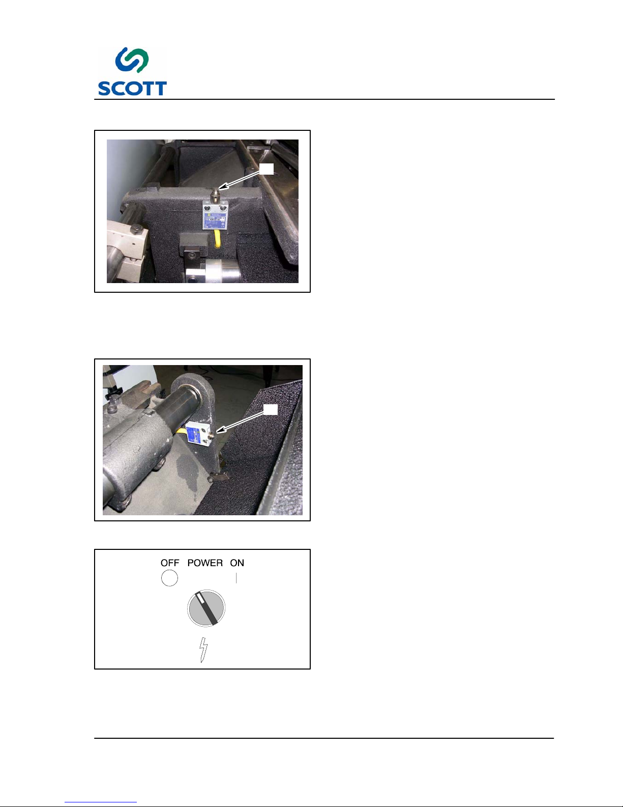
A
Fig. 1-3. Table Safety Switch
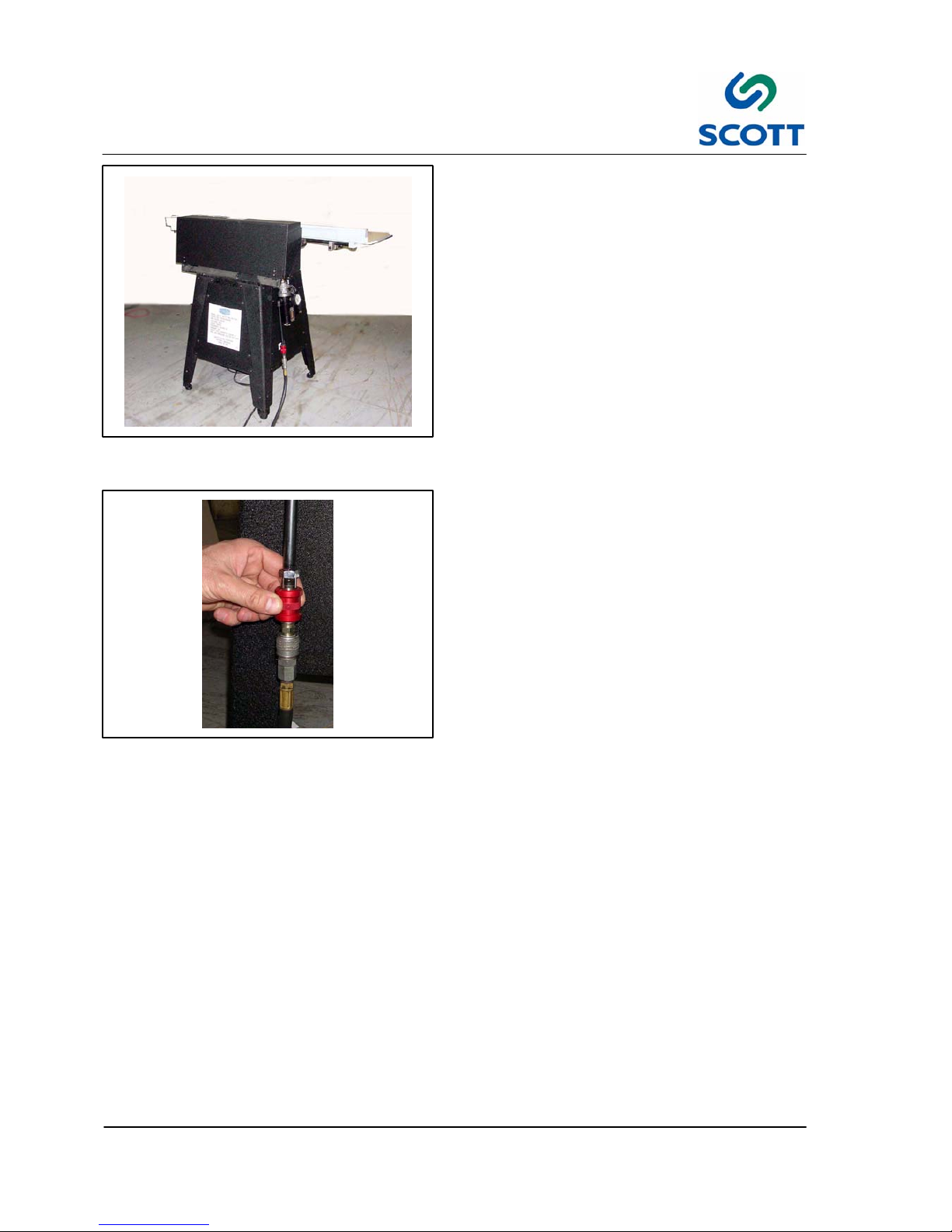
1.3.2 Machine Safety Features
1.3.3 Safety Switches
The machine is equipped with two safety switches.
The table switch (A) is located below the table on
the machine base. The knife guard switch (B) is
located on the base.
When either the table is tilted forward or the knife
guard is open, contact with the switch is broken
and the machine’s main power is disabled.
Once switch contact is broken, it is not necessary
to reset the machine. Machine power is
automatically restored when the table is tilted back
into its correct upright position or the knife guard is
closed.
B
Fig. 1-4. Knife Guard Switch
Fig. 1-5. Turn Machine Off Before Making
Adjustments
1.3.4 Main Power Switch
If machine is to be shut down for adjustments or
repairs, turn the power supply to the machine off.
Page 12
1 Introduction & Safety
1--8
Heavy Duty Tab Cutter Issue 1
Fig. 1-6. Table and Knife Guard Must Be In
Place to Run Machine
1.3.5 Guards and Covers
The table assembly and the knife guard MUST be
in place and securely fastened before operating
the machine. Safety switches will not allow
machine operation unless the table is in the proper
closed position.
Fig. 1-7. Shut Off Main Air Before Working on
Machine
1.3.6 Main Air Disconnect
Shut off main air before making any machine
adjustments.
Page 13
1 Introduction & Safety
1--9
Heavy Duty Tab Cutter Issue 1
1.4 Warnings, Cautions & Notes
In order to emphasize certain areas in the interest of personal safety and a properly operated and maintained
machine, you will encounter the words WARNING, CAUTION, and NOTE throughout this manual.
WARNING!
Fig. 1-8. Warnings Indicate Personal Danger
1.4.1 Warnings
AN OPERATING PROCEDURE,
PRACTICE, ETC. WHICH IF NOT
CORRECTLY FOLLOWED, COULD
RESULT IN PERSONAL INJURY OR
LOSS OF LIFE.
WARNING!
CAUTION!
Fig. 1-9. Cautions Indicate Potential Damage to
Equipment
1.4.2 Cautions
AN OPERATING PROCEDURE,
PRACTICE, ETC. WHICH, IF NOT
STRICTLY OBSERVED, COULD RESULT
IN DAMAGE TO OR DESTRUCTION OF
EQUIPMENT.
CAUTION!
Note !
Fig. 1-10. Notes Indicate Essential Information
1.4.3 Notes
An Operating Procedure, Condition,
etc. Which is Essential To Highlight.
Note !
Page 14
1 Introduction & Safety
1--10
Heavy Duty Tab Cutter Issue 1
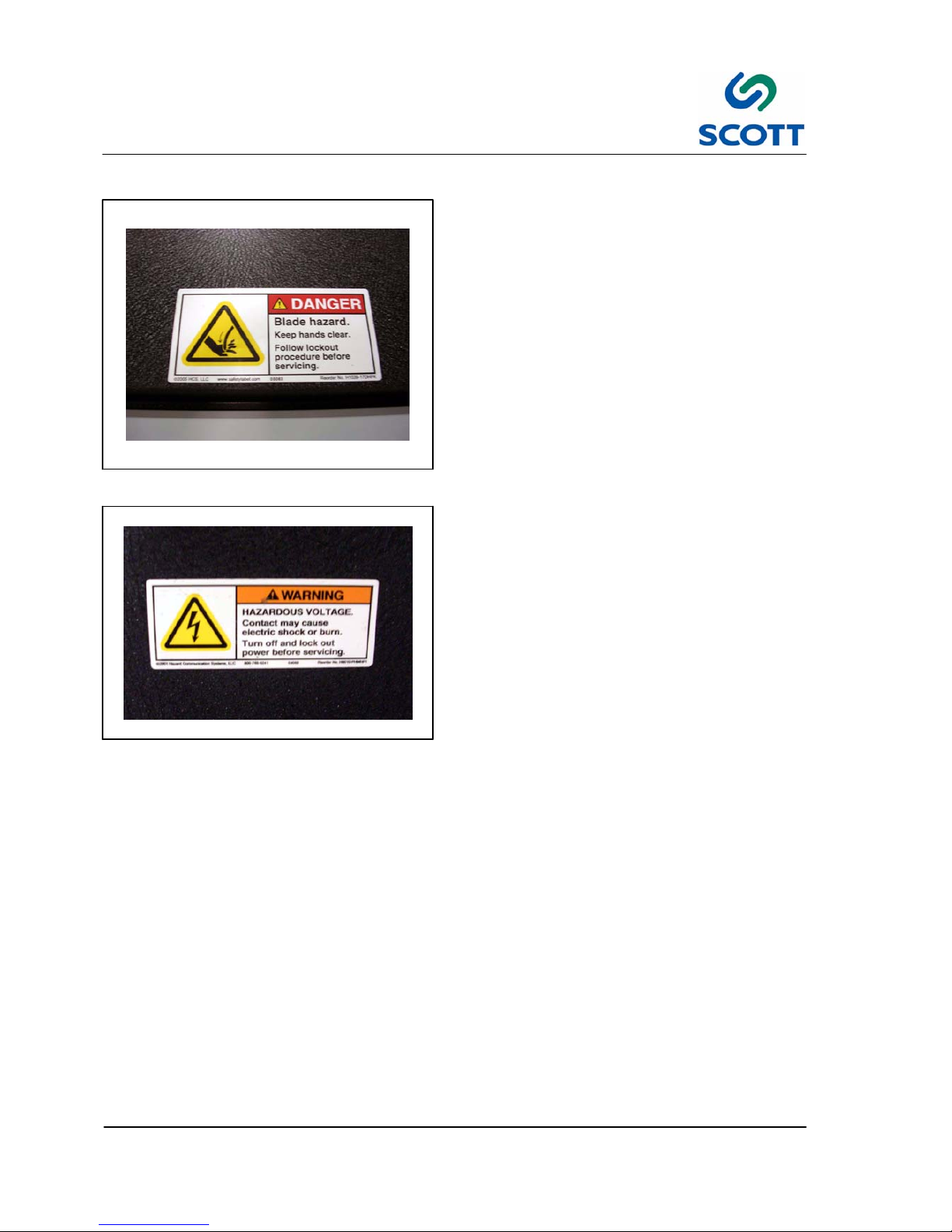
1.5 On Machine Warnings
Fig. 1-11. Cutting Blade Hazard
1.5.1 Hazards
Observe Blade Hazard signs.
Fig. 1-12. Voltage Warning
There is a hazardous voltage warning on the main
electrical cabinet below the operator’s controls.
Page 15
1 Introduction & Safety
1--11
Heavy Duty Tab Cutter Issue 1
1.6 Safety Procedures
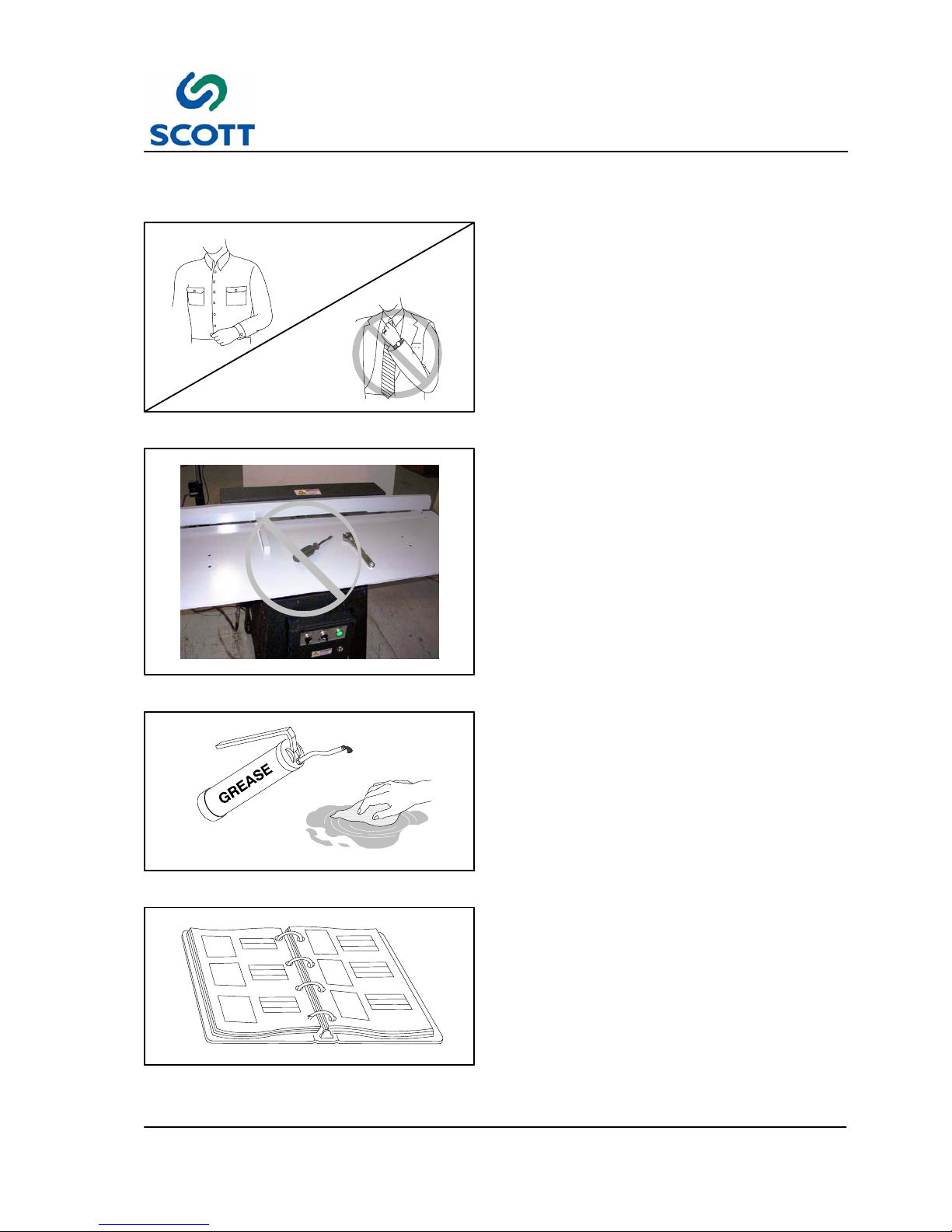
Fig. 1-13. Wear Proper Clothing
1.6.1 Appropriate Dress
Personnel working in the machine operation area
must remove jewelry and neckties. Personnel
must wear clothing appropriate for the work area.
Fig. 1-14. Keep Work Area Clean and Neat
1.6.2 Keep Area Clean
Loose materials, tools and equipment, not
essential to the operation of the machine, must be
removed from the machine work area.
Fig. 1-15. Clean Up Oil and Grease Spills
1.6.3 Grease and Oil
Clean up all oil and grease spills around the
machine work area.
Fig. 1-16. Read Manuals First
1.6.4 Manual Usage
Read and understand the instructions in the
manual before operating, adjusting or servicing
machine.
Page 16

2 Installation
2--1
Heavy Duty Tab Cutter Issue 1
2 INSTALLATION
Heavy Duty Tab Cutter Issue 1
Page 17

2 Installation
2--2
Heavy Duty Tab Cutter Issue 1
Page 18
2 Installation
2--3
Heavy Duty Tab Cutter Issue 1
2.1 Installation Requirements
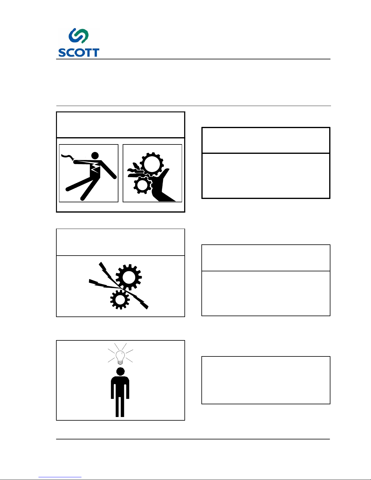
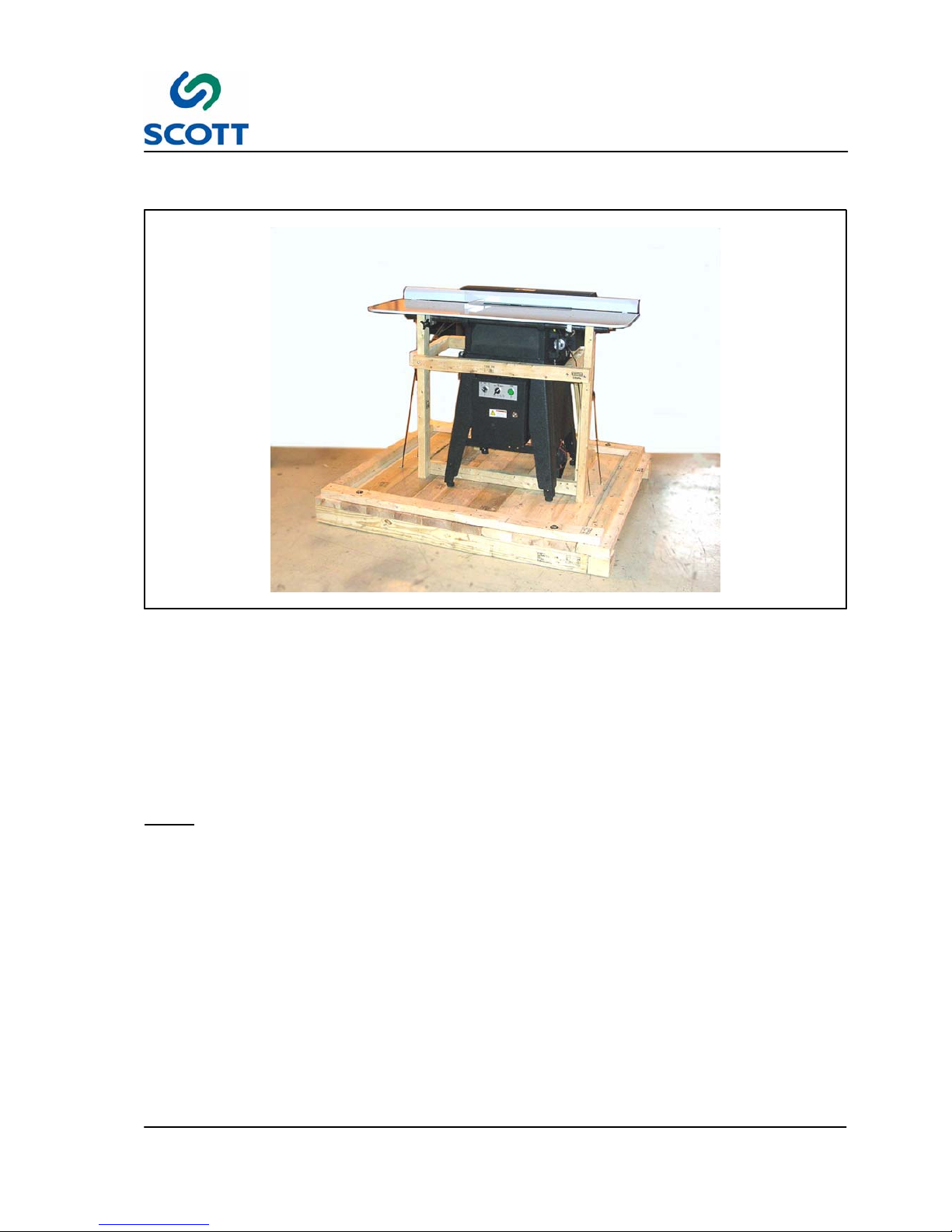
Fig. 2-1. Scott Heavy Duty Tab Cutter on Shipping Skid
All procedures in this section provide advance planning and site preparation data for installation of the Scott
Heavy Duty Tab Cutter. Environmental requirements, unpacking instructions, electrical and physical
specifications are included. This information should be used as a reference during the development of site
preparation plans before you install your machine.
If any questions arise while performing any of the following procedures, contact:
Note ! A forklift is required to lift the machine off the shipping skid and place it on the floor.
Page 19
2 Installation
2--4
Heavy Duty Tab Cutter Issue 1
2.2 Pre-Installation Requirements
The environmental requirements of the Scott Heavy Duty Tab Cutter must be considered well in advance of
the actual installation. Providing a well suited operating environment will help ensure a trouble free
installation process. Consideration should be given to the following items:
● Power, location and rating of power connections.
● Floor strength
● Level floor
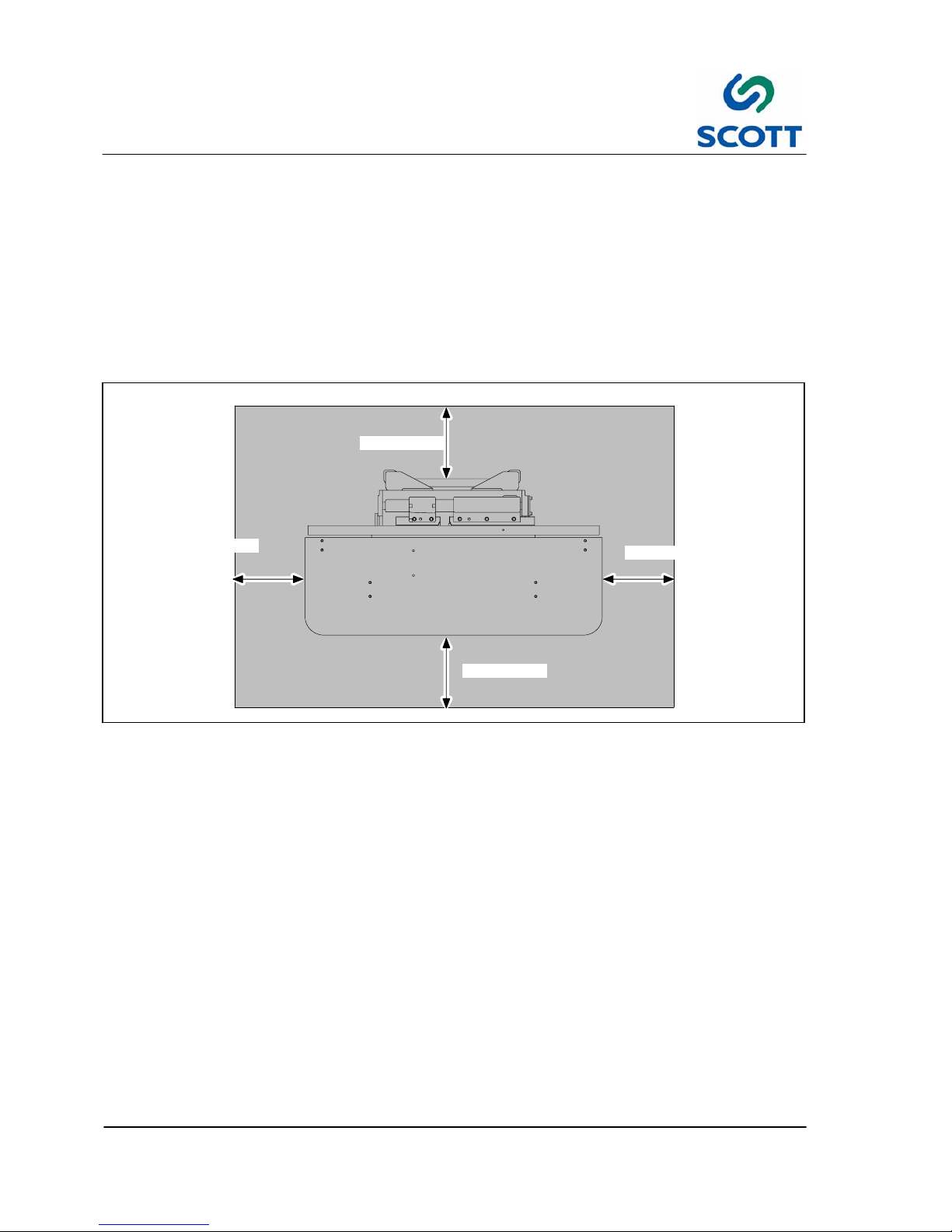
● Adequate space must be provided around all four sides of the machine to permit normal operation and
maintenance procedures. The figure shows the minimum space required.
3’ (914mm)
3’ (914mm)
3’ (914mm)
3’ (914mm)
Fig. 2-2. Scott Tab Cutter Space Requirements
● Space should be allocated near the paper tray for a small table that can be used for small jobs, samples,
etc.
● Provide plenty of space In front of the machine so large jobs can be easily moved in and out with skids or
carts.
Page 20
2 Installation
2--5
Heavy Duty Tab Cutter Issue 1
2.3 Installation Of Scott Heavy Duty Tab Cutter
The machine will arrive in one crate. Inspect the external condition of the crates for visible signs of damage
before opening. If damage is noticeable, notify the carrier and Scott Equipment before proceeding with the
installation.
To assist in the ease of installation, the machine is disassembled prior to shipping and requires some minor
assembly before the machine is operational.
2.4 Assembly Instructions
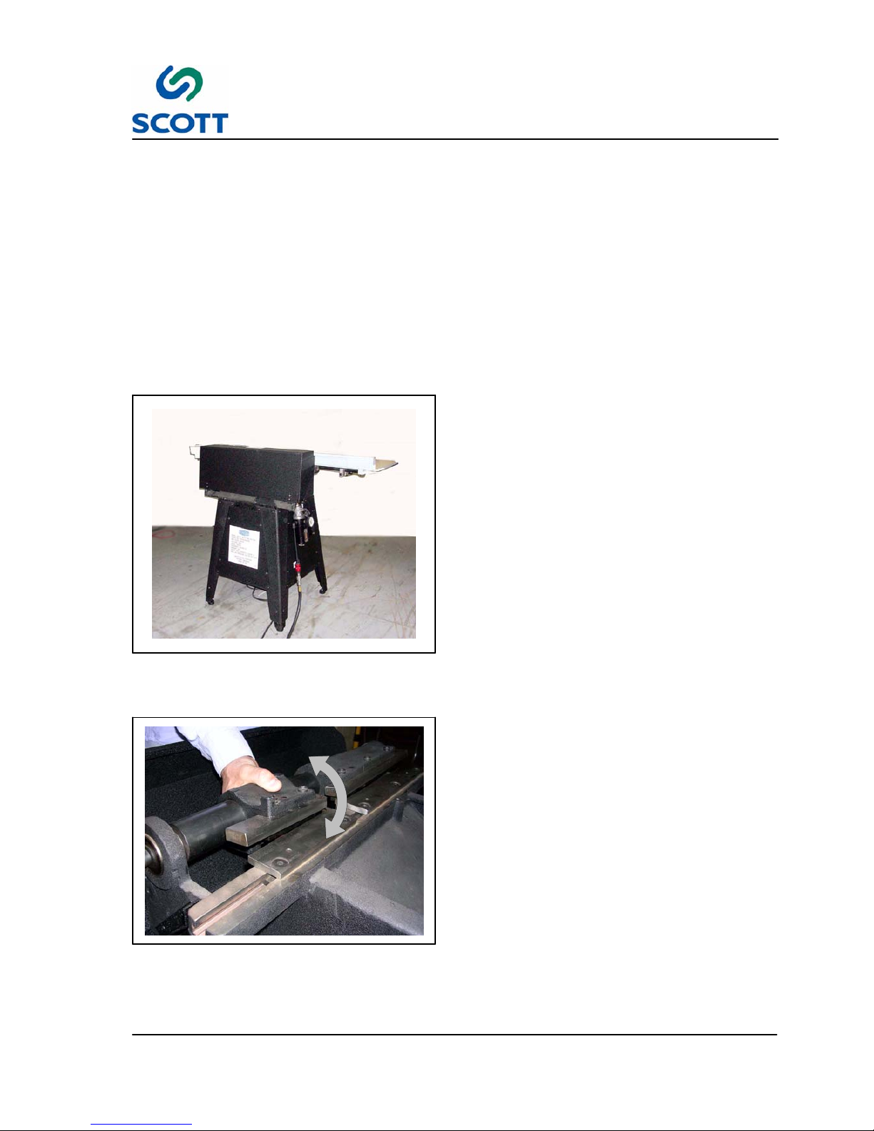
Fig. 2-3. Attach Air Line and Fill Oil Reservoir
2.4.1 Start Up Adjustments
Step: 1. The machine is shipped assembled.
Step: 2. Read labels telling where hoses are
attached. The two lines on the right go to
the air cylinder on the right side of the
machine. The line on the left goes to
elbow on Lubricator Assembly. The
lead--in hose (10’ rubber hose) attaches
to the ball valve (rear) end of the filter
regulator lubricator assembly.
Step: 3. The other end of this hose goes to your
air source.
Step: 4. One pint of non--detergent oil has been
provided with your machine. Remove
fill--plug on top of lubricator assembly,
and fill with oil to the proper level.
Fig. 2-4. Clear Knife Blades
Step: 5. Operate the rotating knife by hand to
check that the shipping did to disturb the
setting.
If the blades clear without hitting,
proceed to tie air into unit from your air
source with the 10’ rubber lead in hose.
Additional adjustment can be made.
The speed of cutting blades are
adjustable by turning a needle valve on
the under side of machine.
Step: 6. Adjust speed so that the action of the
knives does not interfere with the feeding
of stock by the operator.
This helps to take some of the slop out of
the knife action and allows a better
registration by the operator.
Page 21
2 Installation
2--6
Heavy Duty Tab Cutter Issue 1
Note ! There are no other adjustments necessary other than the adjustment of the cutting force
which is done by changing the air pressure.
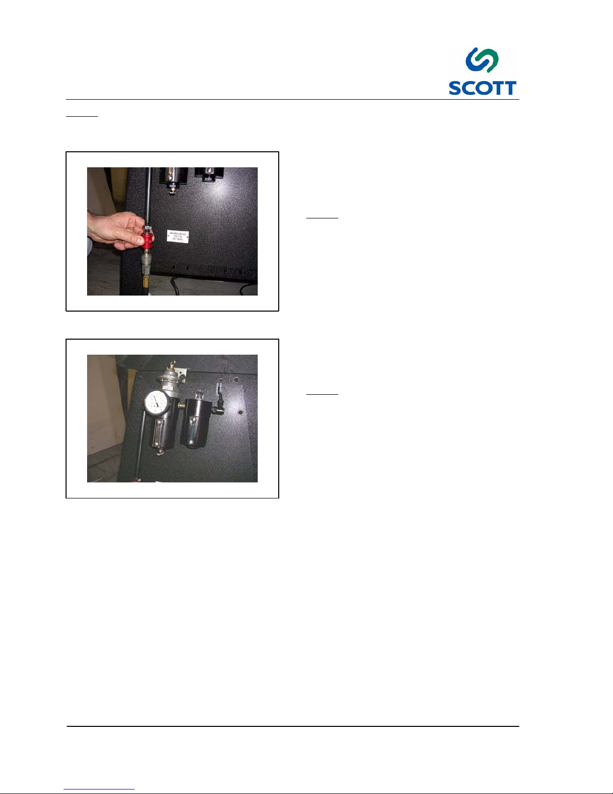
Fig. 2-5. Connect Air Line
Step: 7. Supply a 1/4 NPT air line with 5 ScFm @
80psi (142LPM @ 5.3bar) to the air shut
off valve located at the back of the
machine.
Note ! The compressed air line at the main
AIR IN features a ON/OFF valve for
safety. Place the valve in the closed
(down) position when connecting the
machine to the plant air supply.
Fig. 2-6. Main Air Regulator Set to 50Lbs.
Step: 8. Set the main air regulator to 50psi
(3.4bar). (60lbs is recommend pressure
to use).
Note ! Unit will not operate properly at less
than 50lbs. pressure.
Step: 9. Plug electrical cord plug into a 110 volt
power source.
Page 22

2 Installation
2--7
Heavy Duty Tab Cutter Issue 1
Fig. 2-7. Adjust Lubricator
Step: 10.Locate the Mode Selection switch on the
operator’s panel.
Note ! In the Auto mode, the machine action
is activated by a switch as paper is
inserted.
In the Manual position, the machine is
activated only by the footswitch.
Step: 11.With the Mode switch in the Manual
position, adjust oil flow at lubricator
assembly with screw driver on screw
beside the fill plug. Operate machine
until oil drops appear in the transparent
dome on top of lubricator.
Step: 12.Adjust screw in a clockwise direction until
approximately 10 to 15 cycles of the
machine produce one drop of oil.
See Chapter 4 Maintenance Section for
more information on Lubricator Assembly.
Note ! Keeping oil in lubricator and the filter
clean periodically is your basic
service on the machine.
Page 23

3 Operation
3--1
Heavy Duty Tab Cutter Issue 1
3 OPERATION
Heavy Duty Tab Cutter Issue 1
Page 24

3 Operation
3--2
Heavy Duty Tab Cutter Issue 1
Page 25

3 Operation
3--3
Heavy Duty Tab Cutter Issue 1
3.1 GENERAL INFORMATION
3.1.1 Before Operating the Machine
AVOID SERIOUS INJURY OR EQUIPMENT
DAMAGE. RESTRICT OPERATION OF THIS
MACHINE TO TRAINED, QUALIFIED
PERSONNEL ONLY.
EACH OPERATOR SHOULD KNOW THE
LOCATION AND FUNCTION OF ALL
MACHINE STOPPING CONTROLS.
REVIEW MANUAL FOR EMERGENCY
STOP BUTTON LOCATION.
Do not attempt to operate the machine before reading and understanding the manual. Pay close attention to
all WARNINGS, CAUTIONS and NOTES. Failure to do so may cause serious injury and extensive machine
damage.
Read through the inspection and pre--start procedures before starting the machine. Make these checks part
of your routine to insure efficiency and quality during the production run.
Page 26

3 Operation
3--4
Heavy Duty Tab Cutter Issue 1
3.2 Operator’s Controls
3.2.1 Control Panel Layout
Fig. 3-1. Operator’s Control Panel
Fig. 3-2. Power On/OFF Selector Switch
3.2.2 Power On/OFF Selector Switch
OFF -- Turns Power off to the machine.
ON -- Brings power to the machine.
Fig. 3-3. Machine Mode Selector Switch
3.2.3 Machine Mode Selector Switch
This selector switch determines the operational
mode of the machine.
AUTO -- When the selector switch is in the Auto
mode, the tab cutting blades will operate when a
sheet is inserted into the cutting area. By inserting
a sheet into the cutting area, contact is made with
a switch activating the blades to cut one tab.
OFF -- Tab cutting blades cannot be activated in
this mode.
MANUAL -- When the switch is in this position, the
switch in cutting area is bypassed allowing the tab
cutting operation to be performed using the foot
pedal.
Page 27

3 Operation
3--5
Heavy Duty Tab Cutter Issue 1
Fig. 3-4. Power On Indicator Lamp
3.2.4 Power On Indicator Lamp
Lamp is illuminated when power (power switch in
ON position) is on and all safety switches are in the
“safe” position.
Fig. 3-5. Operator’s Foot Pedal
3.2.5 Foot Pedal
The foot pedal is used by the operator to activate
the tab cutting blades.
NOTE! Machine Mode switch must be in the
Manual position to operate by foot
pedal.
Fig. 3-6. Main Air
3.2.6 Main Air ON/OFF
Slide the quick disconnect up to allow air to the
machine or down to shut it off.
Page 28

3 Operation
3--6
Heavy Duty Tab Cutter Issue 1
A
B
Fig. 3-7. Main Air Regulator & Lubricator
3.2.7 Main Air Regulator & Lubricator
The main air regulator (A) controls the flow of air to
the cutting blade air cylinder. It works in
conjunction with the lubricator (B) to supply a
steady amount of oil to the air cylinder.
Page 29

3 Operation
3--7
Heavy Duty Tab Cutter Issue 1
3.3 Care and Adjustment of Tab Cutting Knives
The Scott tab cutting knives are made of the finest tool steel, hardened and ground. With proper care they
will last indefinitely and will seldom require sharpening.
All personnel should be instructed to handle them with proper care.
They should not be dropped since hardened tool steel will break. They should not be bumped against other
hard surfaces or against themselves since they will nick. Your tab cutting knives are expensive valuable tools
and should be treated as such. When not in use, cover the knives with a thin coat of oil and store in a safe
place.
Fig. 3-8. Turn Off Air, Mode Switch to OFF
3.3.1 Before Adjusting Tab Cutting
Knives:
Before adjusting your tab cutting knives always do
the following:
Step: 1. Shut off Main Air by sliding quick
disconnect down. This allows you to work
the knives up and down by hand and is
is a safety precaution.
Step: 2. Set Mode Switch to OFF.
Fig. 3-9. Loosen Pinch Lock Handles
Step: 3. Loosen the two pinch lock handles at
front under table.
Fig. 3-10. Tilt Table Forward
Step: 4. Tilt the table up.
It will not be possible to adjust the
stationary knives unless the table is in
this position. By tilting the table, the
electricity is disconnected and the knives
will not accidently move.
Page 30

3 Operation
3--8
Heavy Duty Tab Cutter Issue 1
3.4 Setting Tab Cutting Knife Blades
3.4.1 Upper Knife Blades
Before locking the upper knife blades, be sure that both the blades and the paper stops (located under the
blades) are pushed to the back of the knife holder castings. After the upper blades are locked, set the lower
blades as explained below:
3.4.2 Lower Knife Blades
Caution ! IMPORTANT: THE FOLLOWING PROCEDURE MUST BE FOLLOWED OR YOU WILL
DAMAGE YOUR KNIFE BLADES.
Fig. 3-11. Rotate Upper Blade Down
Set only one blade at a time. The following
instructions apply to both the long and short knife
blades.
Step: 1. Rotate the upper blade down as low as
the machine will permit.
Fig. 3-12. Loosen Lower Mounting Blade
Screws
Step: 2. Loosen the lower blade mounting screws.
Page 31

3 Operation
3--9
Heavy Duty Tab Cutter Issue 1
Fig. 3-13. Fit Lower Blade Against Upper Blade
Step: 3. Place the lower blade against the upper
blade so that the lower “fits” the upper at
the contour and the straight edge. Install
the screws but do not tighten yet.
Fig. 3-14. Clear Blade
3.4.3 Clearing the Blades
Then you must “clear the blades”. This is done as
follows:
Step: 1. Remove your hand from the lower blade
so that when you rotate the upper blade,
it will push the lower away.
Step: 2. Grasp the casting holding the upper
blade and rotate it upward to its highest
position and then back downward to its
lowest position. If the lower blade was
too close to the upper, this rotating
procedure will push the lower away from
the upper. The lower blade is now
“cleared”.
Fig. 3-15. Hold Blade and Tighten Mounting
Screws
Step: 3. Hold the lower blade in this “cleared
position” being careful not to push it
against the upper blade. While holding,
tighten screws.
Page 32

3 Operation
3--10
Heavy Duty Tab Cutter Issue 1
Fig. 3-16. Rotate Blades to Make Sure They
Clear
Step: 4. Rotate the upper blade upward and
downward slowly to make sure there is
no bumping or rubbing of the two blades.
If there is bumping or rubbing, repeat the
above procedure for “clearing the
blades”.
Fig. 3-17. Test Cutting Sample Tab
Step: 5. After the blades are “cleared” and locked
in position with no bumping or rubbing,
insert the paper you will be cutting and
rotate the upper blade down to cut. If the
paper does not cut cleanly, repeat the
above procedure.
NOTE! The above procedure must be
followed for both the long and short
lower knife blades.
CAUTION
! NEVER JAM THE BLADES
TOGETHER TO MAKE THEM CUT.
THIS WILL RUIN YOUR BLADES.
If you have followed the procedure
and the knives do not cut well, send
them to Scott Office Systems for
sharpening.
Page 33

3 Operation
3--11
Heavy Duty Tab Cutter Issue 1
Fig. 3-18. Tab Length
3.4.4 To Adjust Knives for Different
Tab Length
It is very simple to change the tab length since only
the short knives must be moved. The long knives
are never adjusted when changing tab length. To
adjust the short knives, do the following:
Fig. 3-19. Loosen Mounting Screws on Small
Stationary Knife
Step: 1. Loosen the two screws holding the small
stationary knife so that it can slide from
left to right or vice versa. Do not remove
the screws, just loosen.
Fig. 3-20. Loosen Mounting Screws on Small
Stationary Knife
Step: 2. Loosen the two bolts at the back of the
casting holding the small rotating knife so
that you can slide the entire unit to the
position on the steel arbor to the position
you want. Do not remove screws, just
loosen.
Page 34

3 Operation
3--12
Heavy Duty Tab Cutter Issue 1
Fig. 3-21. Move to Size, Tighten Mounting
Screws
Step: 3. Slide the small rotating knife casting to
the position desired. The small side
should be approximately level with the
long side.
Step: 4. Tighten mounting screws.
Step: 5. See 3.4 Procedure for Setting Tab
Cutting Knife Blades.
CAUTION
! MAKE SURE YOU HAVE
TIGHTENED SCREWS ON BOTH
KNIVES SECURELY AND NEVER
WORK THE MACHINE
AUTOMATICALLY UNTIL YOU
HAVE DONE IT BY HAND TO
CHECK YOUR SETTING.
Step: 6. Tilt table top down tighten pinch lock
handles, turn on air pressure with ball
valve at lubricator assembly, the machine
is ready for tab cutting.
Fig. 3-22. Loosen Stationary Knife Screws
3.4.5 To Change Knives for New Tab
Extension
To change the tab extension, it is necessary to
remove all four knives and replace with a new set
of four. This is easily done as follows:
Step: 1. Loosen the two screws holding the short
stationary knife. Do not remove screws,
just loosen.
Fig. 3-23. Slide the Knife Out of the Key Slot
Step: 2. Slide lower knife out of its key slots.
Leave the screws and nuts attached for
quick changing the next time you use
knife. Be very careful not to bump, drop
or nick knife. Do the same with the large
stationary knife (three screws to loosen).
Page 35

3 Operation
3--13
Heavy Duty Tab Cutter Issue 1
Fig. 3-24. Loosen Rotating Knife Screws
Step: 3. Loosen the two screws holding the small
rotating knife in the casting and remove
knife by sliding forward. Do not remove
screws, just loosen. Be careful not to
drop bump or nick knife. Do the same
with the large rotating knife (three screws
to loosen).
Fig. 3-25. Store Knives in a Safe Place
Step: 4. Store the four knives in a safe place
where they will not be damaged. Before
storing, put thin coat of oil on all pieces.
Step: 5. Install the new set of four knives.
Step: 6. Set the knives as explained above under
heading Procedure Extension.
NOTE! Remember, after knives are set, work
them all by hand to make sure they do
not bump or rub. Check by cutting a
piece of paper w ith them by hand.
After this, tilt table down, turn on air
with 3- way valve.
Fig. 3-26. Loosen the Table Handles
3.4.6 To Change Tab Position on
Sheet
To change the tab position:
Step: 1. Loosen the two handles at front of
machine so that table will slide from right
to left and left to right.
Page 36

3 Operation
3--14
Heavy Duty Tab Cutter Issue 1
A
Fig. 3-27. Find Position For Feed Guide
Step: 2. Insert a sheet of paper into the cutting
area to find the proper position for feed
guide (A).
Step: 3. Slide the table horizontally so that the
edge of the feed guide is flush with the
sheet edge.
Step: 4. Tighten the two pinch lock handles.
Fig. 3-28. Adjustment for Knife Speed
3.4.7 Cutting Speed of Knives
There is a needle valve under the machine in the
center of the machine. If the knives rotate with too
much or too little speed, you can adjust the speed
with this needle valve.
Page 37

3 Operation
3--15
Heavy Duty Tab Cutter Issue 1
Fig. 3-29. Burrs in Knife Blades
3.4.8 Prevent Knives From Becoming
Deeply Scored
Your knives are made in such a way that they are
“self--clearing” and, theoretically, they should never
touch each other at the cutting edges. They are
made to set very close but should not bump or rub
in operation.
However, it is possible to set them so they do rub
(or possible for grit or foreign matter to get
between them); therefore, it is possible that they
will begin to score.
ANYTIMEYOUNOTICEA“SCORELINE”
APPEARING, STOP THE MACHINE AND CHECK
FOR A BURR.
A small burr, caught in time, will not hurt the cutting
ability of the tab cutting knives. But, a small burr
will eventually work up to become a large burr and
will score the knives deeply. If such a burr is not
removed at once, it will:
● Keep getting larger and score the knives
deeper until they cannot be repaired.
● A burr will prevent you from setting knives
properly since it will not let you set them close
enough.
● Cause poor cutting and ragged edges at cut.
NOTE! Therefore, when you see a “score
line”, contact Scott Office Systems
for information concerning knife
sharpening policy and return
procedures.
Page 38

4 Maintenance
4--1
Heavy Duty Tab Cutter Issue 1
4 MAINTENANCE
Heavy Duty Tab Cutter Issue 1
Page 39

4 Maintenance
4--2
Heavy Duty Tab Cutter Issue 1
Page 40

4 Maintenance
4--3
Heavy Duty Tab Cutter Issue 1
A
Fig. 4-1. Air Cylinder
4.1 Care Of Air Cylinder
4.1.1 Lubrication
The air cylinder actuates the cutting blades.
There is very little that can go wrong with the air
cylinder (A) if it is lubricated properly by the
lubricator. The following will help you to determine
if your Scott is being properly lubricated:
B
Fig. 4-2. Look for Slight Oil Accumulation on
Underside of Valve Muffler
● There should be a slight oil accumulation on the
underside of the exhaust valve’s muffler (B)
This assembly is located directly under the
center of the machine.
Page 41

4 Maintenance
4--4
Heavy Duty Tab Cutter Issue 1
C
Fig. 4-3. Lubricator
Recommended Oil: Mobil DTE24 or Equivalent.
CAUTION
! DO NOT USE DETERGENT OIL;
This type of oil will quickly ruin the
rubber parts in the air cylinder.
USE LIGHT WEIGHT
NON- DETERGENT OIL ONLY. Use
machine oil, spindle oil or mineral oil
only.
Note !DO NOT USE AUTOMOBILE OIL.
With the oil feed clearly seen through the
sightdome (C) in the lubricator, it is possible to
adjust the oil feed to the proper amount of
lubrication. The principle of oil “misting” in
conjunction with the integral automatic by--pass
valve, eliminates the possibility of flooding the
equipment.
D
Fig. 4-4. Adjustment Screw
The Oil Adjustment Screw (D) in the top head of
the lubricator unit may be opened for full flow
(counter--clockwise) or closed completely
(clockwise).
The adjustment screw is held captive by the
hold--down ring on the sightdome, preventing the
screw from being backed out all the way.
Page 42

4 Maintenance
4--5
Heavy Duty Tab Cutter Issue 1
E
Fig. 4-5. Drain Air Regulator Reservoir
Regularly
4.1.1.1 Drain Air Regulator
Operation is entirely automatic and no adjustments
are necessary. To get effective performance, drain
reservoir (E) regularly.
Note ! IF MOISTURE FILLS RESERVOIR
ABOVE LOWER BAFFLE, IT MAY BE
CARRIED OVER INTO THE AIR LINE.
To drain reservoir open drain valve on
filter base.
Fig. 4-6. Clean Air Cylinder Filter Regularly
CAUTION
! TURN OFF AIR BEFORE
DISASSEMBLING.
Step: 1. Unscrew filter base and lower baffle
assembly to remove reservoir and filter
element.
Step: 2. Rinse in petroleum solvent such as
kerosene.
Note !DO NOT USE ACETONE,
ETHYL- ACETATE, TOLUENE, ETC...,
Note ! NEVER EXPOSE PLASTIC BOWL
FILTERS OR LUBRICATORS TO
LUBRICATING OILS OR
COMPRESSOR LUBRICANTS
CONTAINING PHOSPHATE ESTERS.
Step: 3. Clean the plastic bowl units with
household soaps or detergents only.
(See service manual’s enclosed)
Step: 4. Blow out filter element with air hose.
Page 43

4 Maintenance
4--6
Heavy Duty Tab Cutter Issue 1
4.2 Heavy Duty Tab Cutter Spare Parts List
The following are perishable parts. To avoid down--time Scott Office Systems recommend that you keep
them in stock in the quantities shown:
This is a list of all parts on the machine
Part Numbers Part Description Qty.
-- Set of Knife Blades 1
TC--109 Air Cylinder 1
HW--97113 Limit Switch
Page 44

4 Maintenance
4--7
Heavy Duty Tab Cutter Issue 1
4.3 Machine T roubleshooting
Symptom Cause Remedy
Knives pounding in
operation
-- Broken fitting
-- Air Pressure set too high and petcock not adjusted
properly
Locate & Replace
Leak coming from
-- Broken or cracked fitting Locate & Replace
up under valve
plate
-- Broken valve stem
plate
-- Internal airline not sealing
Won’t operate at all -- Not plugged into outlet Plug into outlet
-- Table tilted and interlock not depressed Unclamp table and lay flat
on table rest.
-- Broken or loose wire Inspect wiring & replace or
tighten connection
-- Air Pressure under 50lbs. & valves won’t operate Machine pressure must be
set at a minimum 50lbs.
Adjust
-- Interlock switch vibrated loose & out of locations un-
der safety rod.
Check Interlock
Check mounting screws lo-
cated on valve plate
Operates when using foot pedal but
-- Bent Finger Switch Bend switch finger to trip at
proper point.
notwhen using
f
i
n-
ger switch
-- Defective finger switch Replace Finger Switch
Slow Knife Action -- Lack of Lubrication Check Lube.
You must use Oil Dump Air
and operate manually.
-- Valve blocked or bad. Check Valve & replace if
needed.
-- Muffler blocked. Remove muffler & clean or
replace.
-- Low Air Pressure Check Pressure Gage.
(Min. pressure is 50lbs.)
-- Speed control valve turned too low. Set petcock or needle valve
properly.
-- Blocked filter Clean Lube Assembly Filter
Leaking from Muffler
-- Bad Valve (leaking internally) Locate valve & replace
e
(See 4.3.1 Identify
Leaks From Muffler)
-- Bad Cylinder -- Cylinder is leaking from one side of
the piston inside the cylinder.
Replace Cylinder.
Page 45

4 Maintenance
4--8
Heavy Duty Tab Cutter Issue 1
Fig. 4-7. Disconnect Air Line From Air Cylinder
4.3.1 Identify Leaks From Muffler
If you can hear an air leak from the muffler, use the
following procedure to trouble shoot the problem.
Step: 1. Disconnect the off rod end air line at the
cylinder on the side of the machine and
find out if you have air coming from the
line you just disconnected or from the
fitting you disconnected the line form.
● If air comes from the line, the valve is at fault.
● If air comes from the elbow on the cylinder then
it is the cylinder that is at fault.
There should be no air in this side of the line when
the machine is not electrically energized.
Page 46

4 Maintenance
4--9
Heavy Duty Tab Cutter Issue 1
4.4 C01--1000 Series Filter -- Regulator Combination
4.4.1 Installation
Blow out line to remove foreign matter. Install unit with air flow entering port marked ”IN” or direction of flow
shown on head of unit. Mount in vertical position as close to equipment to be protected as possible. Unit has
dry seal pipe threads, use dope or tape sparingly on male threads only. WARNING: For use in industrial
compressed air systems only. Do not exceed recommended temperature and pressure. Polycarbonate bowl
units can be damaged and burst if exposed to solvents, strong alkalies, fire resistant and synthetic
compressor oils. Use metal bowl in all applications where a plastic bowl could come in contact internally or
externally with chemicals or lubricants incompatible with polycarbonate.
OPERATING SPECIFICATIONS BOWLS
MAX. RECOMMENDED PLASTIC METAL
TEMPERATURE 120_ F 200_ F
PRESSURE 150 PSI 250 PSI
4.4.2 Adjustment
Turning adjustment tee or knob clockwise increases secondary pressure. Adjust secondary pressure with
typical flow conditions (static setting will be slightly higher) and tighten lock nut. Regulator may have a slight
bleed out of bonnet relief hole. This will not affect operation.
4.4.3 Maintenance & Cleaning
A Repair Kit Should be on Hand Unit may be disassembled without removal from airline. SHUT OFF
AIRLINE. Bleed off airline until pressure gauge reads zero. Back off adjustment knob or screw until
compression spring is fully relieved. Refer to drawing as a guide in disassembly. Clean valve seat and
poppet, inspect for pitting, scoring, and roughness. Replace worn or doubtful parts. Filter bowl can be
cleaned with mild soap and water or kerosene. DO NOT USE ANY SOLVENTS. In reassembly, use drawing
as a guide. Do not over--tighten base nut as it shoulders on stud (50--60 lbs.).
ORDER PARTS FROM YOUR LOCAL MONNIER DISTRIBUTOR.
IF ANODIZED, PLEASE INDICATE COLOR.
4.4.4 Vendor Contact Information
Page 47

4 Maintenance
4--10
Heavy Duty Tab Cutter Issue 1
Fig. 4-8. C01--1000 Series Filter--Regulator Combination
Page 48

4 Maintenance
4--11
Heavy Duty Tab Cutter Issue 1
4.5 304--1000 & 2000 Series Lubricators
4.5.1 Installation
WARNING: For use in industrial compressed air systems only. Do not exceed recommended temperature
and pressure. Polycarbonate bowl units can be damaged and burst if exposed to solvents, strong alkalies,
fire resistant and synthetic compressor oils. Use metal bowl in all applications where a plastic bowl could
come in contact internally or externally with chemicals or lubricants incompatible with polycarbonate.
OPERATING SPECIFICATIONS BOWLS
MAX. RECOMMENDED PLASTIC METAL
TEMPERATURE 120_ F 200_ F
PRESSURE 150 PSI 250 PSI
Reservoir can be filled without turning off inlet supply pressure. Remove self--venting fill plug. Fill with good
grade of petroleum lubricating oil approximately 80 to 150 SSU at 100 F (SAE *5 or *10) to within 1/4” of top
of bowl. Unless temperature extremes are present, lighter oils may not wet out and heavier oils could cause
sluggish operation. Replace fill plug hand tight only.
4.5.2 Oil Adjustments
● Clockwise -- Decrease
● Counterclockwise -- Increase
Close oil needle adjustment by turning clockwise. With air flowing through unit, open oil needle adjustment
until you see approximately 2 drops of oil per minute in sight tube for each 20 SCFM. This will vary with air
flow, line pressure, devices lubricated and oil viscosity.
4.5.3 Tamper Proof
After final oil adjustment, unit can be made tamper proof by pressing tamper proof ball in top of sight dome.
TO REMOVE TAMPER PROOF BALL SHUT OFF AIR LINE and bleed off air by removing fill plug. Remove
sight dome assembly. Separate the inner and outer dome. Push tamperproof ball completely out of outer
dome from the inside. Reassemble dome assembly making sure oil adjust needle and small ”0” ring on
needle are assembled into inner dome. Push inner and outer domes together. Make sure ”0” ring, bottom of
inner dome and ”0” ring under hex of outer dome are in position. Reassemble dome assembly and fill plug.
Turn on air supply and follow oil adjustment instructions.
ORDER PARTS FROM YOUR LOCAL MONNIER DISTRIBUTOR. IF ANODIZED, PLEASE INDICATE
COLOR.
4.5.4 Maintenance
SHUT OFF AIR SUPPLY. Loosen oil fill plug to vent bowl. Bowl can now be removed by removing base nut
for cleaning with mild soap and water or kerosene. Do not use solvents, thinners or carbon tetrachloride. If
bowl seal remains in head, remove, inspect and replace if necessary. Open adjustment needle full
(counterclockwise). Use blow gun to blow air through oil pickup tube and sight dome assembly . To
reassemble unit make sure bowl seal is into head groove or on top of bowl. Position bowl in place and install
base nut with ”0” ring. Turn bowl slightly to make sure bowl centers into head groove. Do not attempt to over
tighten base nut as it shoulders on stud. Follow procedure for filling reservoir and oil adjustment.
Page 49

4 Maintenance
4--12
Heavy Duty Tab Cutter Issue 1
Fig. 4-9. 304--1000 & 2000 Lubricators
4.5.5 Part Information
Bowl Kit Series
21557 1000
21558 1200
21559 P or T 1300
22520 P or T 2200
22521 P or T 2300
Suffix P--Polycarbonate
T--Trogamid
Seal Kit 21555
4.5.6 Vendor Contact Information
Page 50

5Parts
Page 5-1
Heavy Duty Tab Cutter Issue 1 07/2005
5 PARTS
Heavy Duty Tab Cutter
TC--99999--1
Issue 1 07/2005
Page 51

Page 5-2
5Parts
Heavy Duty Tab Cutter Issue 1 07/2005
SCOTT OFFICE SYSTEMS PARTS ORDERING INFORMATION
1. When corresponding or ordering parts from Scott Office Systems include complete Business Name, Street Ad-
dress, City, State, Country, Zip Code and Machine Serial Number.
2. Order by part number and description as shown in the manual.
3. Specify how shipments are to be made -- Freight, Parcel Post, or Express. If routing is not specified, we will use
our own judgement and not be responsible for the additional costs or delays.
4. Always confirm fax or phone orders by clearly marking “Confirmation”.
5. Address all correspondence to:
Page 52

5Parts
Page 5-3
Heavy Duty Tab Cutter Issue 1 07/2005
PARTS RETURN
To enable us to handle credit efficiently and promptly, and to save our Customers unnecessary expense and delay, the
following procedures have been established.
1. Customers are requested not to return parts of any kind without first communicating by letter or telephone with the
Parts Service Department. We will advise what procedures to follow to expedite the issue of credit and the applicable
restocking charge. A Return Material Code Number indicating the authorization to return parts will be issued. NOTE:
Proof of purchase must be established before credit can be approved.
2. All shipments returned MUST contain a copy of the Invoice Number or Packing List that parts were received on and
the reason for return noted. Shipments may be refused if the above procedure is not followed.
3. No parts are to be returned without a Return Authorization Number issued by Parts Service.
4. Requests for credit of returned parts must contain Invoice Number and Date of Purchase.
5. Parts are to be returned “Prepaid”.
6. Parts shipped out over one (1) year cannot be accepted. Any parts for which an invoice (proof of purchase) cannot
be found, will not be accepted.
7. Return all Parts to
8. Restocking charge is $25.00 or 10% whichever is greater.
9. Warranty Part Shipments -- Shipment of parts under warranty will be handled by U.P.S. Ground. Customer will incur
all shipping expenses by other than U.P.S. Ground.
Page 53

A
VIEW-- A
Page 5-4
5Parts
Heavy Duty Tab Cutter Issue 1 07/2005
5.1 Knife Assembly
Page 54

5Parts
5.1 Knife Assembly
Page 5-5
Heavy Duty Tab Cutter Issue 1 07/2005
ITEM # PART # DESCRIPTION #REQ ITEM # PART # DESCRIPTION #REQ
1 TC-- 0001 BODY 1
2 HW--51540 SCREW, SOC HD, 2
3 HW--41920 WASHER, FLAT HARDENED, 2
4 HW--66090 BEARING, BALL, 2
5 HW--54200 SCREW, FLAT HD, 5
6 TC-- 0072 KNIFE, LOWER LH, 1
7 TC-- 0073 KNIFE, LOWER RH, 1
8 TC-- 0012 NUT 5
9 TC-- 0005 SHAFT, PIVOT 1
10 TC--0003 KNIFE HOLDER, LH 1
11 TC--0002 KNIFE HOLDER, RH 1
12 HW--56200 PIN, DOWEL, 2
13 HW--51500 SCREW, SOC. HD, 5
14 HW--51490 SCREW, SOC. HD, 4
15 TC--0071 KNIFE, UPPER LH, 1
16 TC--0004 PAPER STOP, SHORT LH 1
17 TC--0074 KNIFE, UPPER RH, 1
18 TC--0007 PAPER STOP, LONG RH 1
19 HW--51380 SCREW, SOC. HD, 2
20 TC--0006 CAP, BEARING 1
Page 55

REF:
TC--0001 BOD Y, TAKEN
FROM PREVI O US PAGE.
Page 5-6
5Parts
Heavy Duty Tab Cutter Issue 1 07/2005
5.2 Table Assembly
Page 56

5Parts
5.2 Table Assembly
Page 5-7
Heavy Duty Tab Cutter Issue 1 07/2005
ITEM # PART # DESCRIPTION #REQ ITEM # PART # DESCRIPTION #REQ
1 TC-- 0009 TABLE 1
2 HW--51290 SCREW, SOC. HD, 8
3 TC-- 0020 BRACKET, PAPER GUIDE MTG. 2
4
TC--0011 GUIDE, SIDE 1
HW--53200 SCREW, BUTTON HD, 2
HW--49040 WASHER, FLAT 2
5 TC-- 0010 SHAFT, TABLE 1
6 HW--81100 KNOB, 4--PRONG, 2
7
TC--0014 TABLE, LOCK 2
HW--57030 PIN, SPRING, 2
8 HW--55420 SCREW, HEX HD, 2
9 HW--56140 PIN, DOWEL, 1
Page 57

REF:
ASSEMBLY TAKEN FRO M
PREVIOUS PAGE.
Page 5-8
5Parts
Heavy Duty Tab Cutter Issue 1 07/2005
5.3 Paper Guide Assembly
Page 58

5Parts
5.3 Paper Guide Assembly
Page 5-9
Heavy Duty Tab Cutter Issue 1 07/2005
ITEM # PART # DESCRIPTION #REQ ITEM # PART # DESCRIPTION #REQ
1 TC-- 0024 PAPER GUIDE, KNIFE COVER 1
2 HW--51490 SCREW, SOC. HD, 2
Page 59

REF:
TC--0001 BOD Y, TAK EN FROM
KNIFE ASSEMBLY PAGE.
REF:
TC--0002 KNIFE HO L DER, TAKEN
FROM KNIFE ASSEMBLY PAGE.
Page 5-10
5Parts
Heavy Duty Tab Cutter Issue 1 07/2005
5.4 Air Cylinder Assembly
Page 60

5Parts
5.4 Air Cylinder Assembly
Page 5-11
Heavy Duty Tab Cutter Issue 1 07/2005
ITEM # PART # DESCRIPTION #REQ ITEM # PART # DESCRIPTION #REQ
1
TC--0022--1 PIN, CLEVIS LONG 1
HW--57510 PIN, COTTER, 1
2 TC-- 0015 BAR, CYLINDER MTG. 1
3 HW--51460 SCREW, SOC. HD, 2
4
TC--0023 PIN, CLEVIS SHORT 1
HW--57510 PIN, COTTER, 1
5 TC-- 0109 AIR CYLINDER 1
6 HW--63500 ELBOW, 2
7 TC-- 0027 GUARD, CYLINDER 1
8
HW--53140 SCREW, BUTTON HD, 3
HW--49040 WASHER, FLAT 3
9 TC-- 0022 CLEVIS 1
10
HW--52020 SCREW, SET, 1
HW--84010 BALL, NYLON 1
Page 61

AIR CYLINDER
FRONT PORT
AIR CYLINDER
BACK PORT
TO AIR SUPPLY
Page 5-12
5Parts
Heavy Duty Tab Cutter Issue 1 07/2005
5.5 Air Valve Assembly
Page 62

5Parts
5.5 Air Valve Assembly
Page 5-13
Heavy Duty Tab Cutter Issue 1 07/2005
ITEM # PART # DESCRIPTION #REQ ITEM # PART # DESCRIPTION #REQ
1 TC-- 0013 PLATE 1
2
HW--53200 SCREW, BUTTON HD, 2
HW--49040 WASHER, FLAT 2
3 TC-- 0018 PLATE 1
4
HW--97013 SWITCH, MICRO, 1
HW--55190 SCREW, THUMB, 2
5 HW--47100 MUFFLER,
6 TC-- 0019 BRACKET, SWITCH 1
7
HW--63500 ELBOW, 5
HW--63140 TUBING, URETHANE 10 FT.
8 TC-- 0197 AIR VALVE, 4--WAY 1
9 HW--63480 TEE, STREET 1
10 HW--63490 NEEDLE, VALVE, 1
Page 63

AIR SUPPLY IN
REF:
S--1004 SIDE RAIL , TAKEN
FROM STAND ASSEMBLY.
FROM PORT #1
Page 5-14
5Parts
Heavy Duty Tab Cutter Issue 1 07/2005
5.6 Air Supply Assembly
Page 64

5Parts
5.6 Air Supply Assembly
Page 5-15
Heavy Duty Tab Cutter Issue 1 07/2005
ITEM # PART # DESCRIPTION #REQ ITEM # PART # DESCRIPTION #REQ
1
HW--63500 ELBOW, 1
HW--63140 TUBING, URETHANE REF
2
HW--53180 SCREW, BUTTON HD, 1
HW--49040 WASHER, FLAT 1
HW--60290 NUT, HEX 1
3 AIR SUPPLY 1
Page 65

REF:
TC--0001 BOD Y, TAK EN FROM
KNIFE ASSEMBLY PAGE.
REF:
TC--0013 PLATE, TAKEN
FROM PREVIOUS PAGE.
Page 5-16
5Parts
Heavy Duty Tab Cutter Issue 1 07/2005
5.7 Knife Guard Assembly
Page 66

5Parts
5.7 Knife Guard Assembly
Page 5-17
Heavy Duty Tab Cutter Issue 1 07/2005
ITEM # PART # DESCRIPTION #REQ ITEM # PART # DESCRIPTION #REQ
1
HW--51370 SCREW, SOC. HD, 4
HW--49050 WASHER, FLAT 4
2
TC--0028 GUARD, RIGHT END KNIFE 1
HW--53140 SCREW, BUTTON HD, 2
3
TC--0029 GUARD, LEFT END KNIFE 1
HW--53140 SCREW, BUTTON HD, 2
4
HW--55040 BOLT, SHOULDER, 2
HW--49090 WASHER, TOOLING 4
5 TC-- 0025 BLOCK, HINGE 2
6 TC-- 0026 GUARD, KNIFE 1
7
HW--53060 SCREW, BUTTON HD, 4
HW--49080 WASHER, FLAT HARDEN, 4
8
HW--97011 SWITCH, PLUNGER LIMIT, 1
HW--53080 SCREW, BUTTON HD, 2
9
HW--97012 SWITCH, ROLLER LIMIT, 1
HW--53080 SCREW, BUTTON HD, 2
Page 67

Page 5-18
5Parts
Heavy Duty Tab Cutter Issue 1 07/2005
5.8 Leg Extension Assembly
Page 68

5Parts
5.8 Leg Extension Assembly
Page 5-19
Heavy Duty Tab Cutter Issue 1 07/2005
ITEM # PART # DESCRIPTION #REQ ITEM # PART # DESCRIPTION #REQ
1 TC-- 1016 STAND, LEFT FRONT LEG 1
2 TC-- 1017 STAND, RIGHT FRONT LEG 1
3 R-- 1002 LEG STAND EXTENSION 4
4
HW--53180 SCREW, BUTTON HD, 8
HW--60290 NUT, HEX 8
HW--49040 WASHER, FLAT 8
5
HW--53202 SCREW, BUTTON HD, 4
HW--49040 WASHER, FLAT 4
HW--60290 NUT, HEX 4
HW--99232 BUMPER, RUBBER
MCMASTER/CARR,
4
6 S--1008 STAND, LEG 2
Page 69

REF:
TC--1017 FRON T RIGHT LEG STAND
TAKEN FROM PREVIOUS PAGE.
REF:
TC--1016 FRON T LEFT LEG STAND
TAKEN FROM PREVIOUS PAGE.
REF:
S--1008 LEG STAND TAKEN
FROM PREVIOUS PAGE.
Page 5-20
5Parts
Heavy Duty Tab Cutter Issue 1 07/2005
5.9 Machine Mounting Rail Assembly
Page 70

5Parts
5.9 Machine Mounting Rail Assembly
Page 5-21
Heavy Duty Tab Cutter Issue 1 07/2005
ITEM # PART # DESCRIPTION #REQ ITEM # PART # DESCRIPTION #REQ
1 TC-- 1004 RAIL, SIDE 4
2
HW--54130 SCREW, FLAT HD, 4
HW--60290 NUT, HEX 4
3 S--1002 RAIL, MACHINE MTG. 2
4 TC-- 1005 CLIP, RAIL MTG. 4
5
HW--53180 SCREW, BUTTON HD, 12
HW--60290 NUT, HEX 12
HW--49040 WASHER, FLAT 12
Page 71

REF:
TC--1016 FRON T LEFT LEG STAND TAKEN
FROM LEG EXTENSION ASSEMBLY PAGE.
REF:
TC--1017 FRON T RIGHT LEG STAND TAKE N
FROM LEG EXTENSION ASSEMBLY PAGE.
REF:
S--1008 LEG STAND TAKEN FROM LEG
EXTENSION ASSEMBLY PAGE.
Page 5-22
5Parts
Heavy Duty Tab Cutter Issue 1 07/2005
5.10 Bottom Support Rail Assembly
Page 72

5Parts
5.10 Bottom Support Rail Assembly
Page 5-23
Heavy Duty Tab Cutter Issue 1 07/2005
ITEM # PART # DESCRIPTION #REQ ITEM # PART # DESCRIPTION #REQ
1 TC-- 1004 RAIL, SIDE 4
2
HW--54130 SCREW, FLAT HD, 4
HW--60290 NUT, HEX 4
3 S--1003 RAIL, BOTTOM SUPPORT 2
4 TC-- 1005 CLIP, RAIL MTG. 4
5
HW--53180 SCREW, BUTTON HD, 8
HW--60290 NUT, HEX 8
HW--49040 WASHER, FLAT 8
Page 73

REF:
TC--1016 FRON T LEFT LEG STAND TAKEN
FROM LEG EXTENSION ASSEMBLY PAGE.
REF:
TC--1017 FRON T RIGHT LEG STAND TAKE N
FROM LEG EXTENSION ASSEMBLY PAGE.
REF:
S--1008 LEG STAND TAKEN FROM LEG
EXTENSION ASSEMBLY PAGE.
Page 5-24
5Parts
Heavy Duty Tab Cutter Issue 1 07/2005
5.11 Guard Assembly
Page 74

5Parts
5.11 Guard Assembly
Page 5-25
Heavy Duty Tab Cutter Issue 1 07/2005
ITEM # PART # DESCRIPTION #REQ ITEM # PART # DESCRIPTION #REQ
1
HW--53180 SCREW, BUTTON HD, 14
HW--49040 WASHER, FLAT 14
2 TC-- 1018 GUARD, FRONT ENCLOSURE 1
3 S--1016 GUARD, SIDE 3
4 TC-- 1020 TAG, MAIN MACHINE 1
Page 75

REF:
TC--1016 FRON T LEFT LEG STAND TAKEN
FROM LEG EXTENSION ASSEMBLY PAGE.
REF:
TC--1017 FRON T RIGHT LEG STAND TAKE N
FROM LEG EXTENSION ASSEMBLY PAGE.
Page 5-26
5Parts
Heavy Duty Tab Cutter Issue 1 07/2005
5.12 Controls Mounting Assembly
Page 76

5Parts
5.12 Controls Mounting Assembly
Page 5-27
Heavy Duty Tab Cutter Issue 1 07/2005
ITEM # PART # DESCRIPTION #REQ ITEM # PART # DESCRIPTION #REQ
1 TC-- 1019 ENCLOSURE ASSEMBLY 1
2
HW--53180 SCREW, BUTTON HD, 6
HW--49040 WASHER, FLAT 6
3 TC-- 1015 ENCLOSURE MOUNT 1
 Loading...