

Page 1

MF400 SERVICE PARTS
This is the parts list for all MF400 model
units.
There are two very different models, the first
was the MF400 "A" series, as in
MF400AE-1A. This unit was produced from
1978 unitl early 1989. In the spring of 1989,
the MF400 "B" (MF400AE-1B) series
production began. The complete model
number must be checked, especially when
ordering evaporator and ice spout parts.
Table Of Contents
Major Assemblies...............................................................................................................Page 2-3
Cabinet ...............................................................................................................................Page 4
Compressor........................................................................................................................Page 5
Spout ..................................................................................................................................Page 6
Evaporator "B" Model.........................................................................................................Page 7
Evaporator "A" Model.........................................................................................................Page 8
Gearmotor...........................................................................................................................Page 9
Control Box.........................................................................................................................Page 10
Wiring Diagrams.................................................................................................................Page 11-14
Page 2
45
11
30
31
36
MF400 SERVICE PARTS
"A" Model Only
39
40
24
44
25
22
43
42
41
28
29
32
33
9
34
7
27
26
35
17,18,19,
20,21
3
4,5
16
13,14
8
23
15
37,38
12
10
6
2
1
May, 1991
Page 2
Page 3

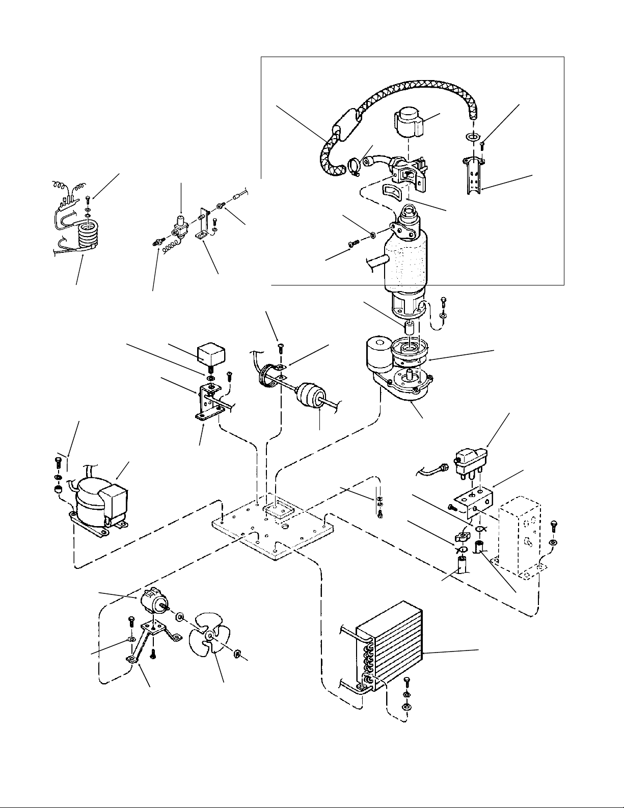
MF400 SERVICE PARTS
MAJOR ASSEMBLIES
ITEM PART
NUMBER NUMBER DESCRIPTION
1. 18-3309-01 Fan Blade
2. 18-0422-00 Fan Motor Bracket
3. 12-1576-01 Fan Motor
4. 03-1417-09 Lockwasher
5. 03-0571-00 Hex Head Screw
6. 18-3717-01 Air Cooled Condenser
7. A09386-000 Drier Brace
8. 02-2426-01 Drier
9. 03-1360-01 Mounting Screw
10. 13-0079-03 Reservoir Overflow Tube, order per ft.
11. 02-0535-01 Hose Clamp
12. 03-0694-00 Hose Clamp
13. 02-2217-01 Reservoir, Inlcudes Valve
14. 02-2217-02 Valve Only, For Reservoir
15. A20959-000 Mounting Bracket
16. 18-4500-01 Compressor
17. 18-2200-28 Grommet
18. 18-2200-27 Mounting Sleeve
19. 03-1417-12 Lockwasher
20. 03-1408-29 Special Washer
21. 03-1405-40 Mounting Screw
22. 11-0296-00 Low Water Pressure Control
23. A27993-001 Utility Bracket
24. 13-0617-26 O-ring
25. 03-1394-00 Pal Nut
26. A30487-001 Bin Thermo Bracket
27. 13-0806-01 Sealing Pad
28. A26537-004 Ice Tube
29. 02-0179-02 Hose Clamp
30. 13-0815-01 Freezer Cap
31. 13-0679-00 Spout Gasket
32. 03-1417-07 Washer
33. 03-1544-03 Soc-hd Cap Screw
34. A29915-002 Coupling
35. 13-0628-00 Gasket
36. A31977-001 Complete Gearmotor
37. 03-1417-09 Lockwasher
38. 03-1405-03 Hex Hd Cap Screw
39. 18-3303-02 Water Cooled Condenser
40. 03-0571-00 Hex Hd Screw
41. 16-0677-01 Half Union
42. A15924-000 Pipe Bracket/nipple Assmbly
43. 11-0198-02 Water Regulating Valve
44. 16-0355-00 Coupling
45. 13-0674-09 Reservoir tube, order per ft.
May, 1991
Page 3
Page 4
10
11
MF400 SERVICE PARTS
2
1
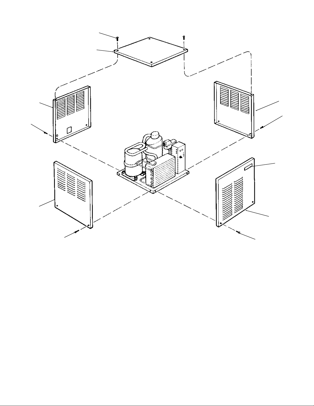
Cabinet
4
5
6
5
5
9
5
ITEM PART
NUMBER NUMBER DESCRIPTION
1 A26625-003 Top panel, painted
A26625-002 Top panel, stainless
2 03-1419-09 Flat head screw
3 03-1423-06 Speed nut
4 A28048-001 Back panel
A28048-002 Back panel, stainless
5 03-1404-09 Panel Screw
6 A26623-003 Left side panel
7 A26623-003 Left side panel, stainless
8 03-1507-00 Speed nut
9 A26624-003 Right side panel
A26624-002 Right side panel
10 A27111-003 Front panel, painted
A27111-002 Front panel, stainless
11 15-0718-01 Emblem
May, 1991
Page 4
Page 5
MF400 SERVICE PARTS
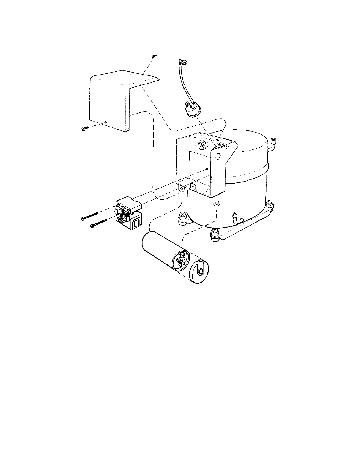
Compressor
COMPRESSOR
ITEM PART
NUMBER NUMBER DESCRIPTION
1. 18-4500-01 Compressor
2. 18-1901-33 Start capacitor
3. 18-2200-25 Overload
4. 18-2200-26 Relay
May, 1991
Page 5
Page 6

6
4
16
9
3
MF400 SERVICE PARTS
"B" Model Spout
ITEM PART
NUMBER NUMBER DESCRIPTION
1 05-0582-01 Ice Tube Assy (only for metal spout)
2 A34519-001 Bin Thermo Bracket
3 03-1587-02 Wing nut
4 no number Spout*
5 A34704-001 Cap Assy (fits metal
spout only)
6 13-0877-01 Grommet (use with
plastic spouts only)
7 03-1403-46 Screws
8 12-1018-01 Microswitch
9 A34515-001 Speed nut
10 03-1403-09 Screw
11 A34700-001 Plate
12 A34516-001 Switch plate
13 A34522-001 Grommet (use with
plastic spouts only)
14 02-3207-01 Upper spacer
15 02-3207-02 Lower spacer
16 02-3200-01 Spout insul. half
02-3200-02 Spout insul. half
1
10
7
8
3
9
13
14
5
15
11
*Kit to change early model units with plastic
spout to current metal spout: A35350-001
Change to metal spout began with
May, 1991 production.
"A" MODEL SPOUT
ITEM PART
NUMBER NUMBER DESCRIPTION
1. A26542-001 Ice Discharge elbow
2. 13-0617-41 O-ring
3. 12-1664-00 Switch
4. 03-1418-38 Screw
5. 03-1417-01 Lockwasher
6. 03-1406-01 Nut
7. 02-2377-01 Thermal Barrier
8. 03-1418-01 Screw
9. A27511-001 Switch actuator
10. A25305-001 Shoulder screw
11. A24934-001 Spout Casting
11
3
2
2
4
7
12
1
10
8
5
6
May, 1991
Page 6
Page 7

MF400 SERVICE PARTS
Evaporator for "B" series
ITEM PART
NUMBER NUMBER DESCRIPTION
1 03-1558-03 Retainer Ring
2 A08162-000 Cap Hook
3 A07701-000 Cap
4 03-0758-00 Screw
5 A07699-000 Washer
6 02-1412-00 Top Bearing Set
7 13-0617-16 O-Ring
8 A14678-020 Breaker with Bearing
Includes 6,7,8
9 A29669-001 Auger
10 02-1300-01 Water Seal
11 02-0417-00 Lower Bearing
12 A29915-002 Spline Coupling
13 03-1505-00 Gasket
14 03-1410-04 Washer (3)
15 03-1420-01 Cap Screw (3)
16 08-0595-01 Adapter
17 13-0709-01 Water shed
18 A34500-020 Evaporator**
19 03-1417-07 Washer
20 03-1403-46 Screw
* Tapered bearing set,
assembly is critical,
refer to service manual
for instructions.
** Not available as an assemlby, but includes
parts to change to metal spout design.
May, 1991
Page 7
Page 8

12
MF400 SERVICE PARTS
4
5
6
7
1
20
9
8
10
11
"A " MODEL EVAPORATOR
ITEM PART
NUMBER NUMBER DESCRIPTION
1 A18430-002 Spout Plate
2. 03-1409-14 Washer
3. 03-1506-01 Sealing Screw
4. A08162-000 Cap Hook
5. 03-1558-03 Retaining Ring
6. A07701-000 Cap
7. 03-0758-00 Cap Screw
8. A26707-001 Bearing Retainer
With Bearing
9. 02-0695-00 Top Bearing
10 13-0617-16 O-ring
2
3
18
16
17
13
ITEM PART
NUMBER NUMBER DESCRIPTION
11. 13-0617-29 O-ring
12. A29622-001 Auger
13. 08-0595-01 Adaptor
14. 03-1401-04 Lockwasher
15. 03-1420-01 Hex cap screw
16. 03-1505-00 Gasket
17. 02-0417-00 Bottom Bearing
18. 02-1300-01 Water seal,
two part set
19. A29344-020 Evaporator only*
20. A07699-000. Washer
19
20
15
* Evaporator is not a vailable as an
assembled part. All parts must be ordered
individually.
May, 1991
Page 8
Page 9

MF400 SERVICE PARTS
GEARMOTOR
ITEM PART
NUMBER NUMBER DESCRIPTION
1. 12-2059-01 Switch
2. A27895-001 Housing
3. A27494-001 Centrifugal Sw. Kit
4. 03-1403-77 Screw
5. A30579-001 Shaft and Actuator
6. 03-1408-36 Washer
7. 02-1503-00 Grease seal
13-0841-01 Water shed, not illus
8. 03-1408-21 Washer
9. 03-1408-04 Washer
10. 02-2445-01 Output shaft
11. 03-1515-03 Retaining ring
12. 03-1602-01 Woodruff Key
13. 02-2444-01 Output gear
14. 02-1505-00 O-ring
15. 03-0774-11 Roll pin
16. A28166-001 Gear Case
17. 03-1408-39 Washer
18. 03-1408-40 Washer shim
19. 02-2439-01 Second gear and
third pinion
20. 03-1408-41 Washer
21. 03-1408-38 Washer
22. 02-2438-01 First gear and
second pinion
23. A28165-021 Gear box cover
24. 02-3969-20 Grease seal
25. 02-1501-00 Bearing
26. 03-1408-08 Washer
27. A37707-021 Motor kit
28. no number, part of item 27
29. A28168-001 Fan
30. A38501-001 Motor Housing
with bearing
31. A25835-001 Oil
32. A31977-021 Complete Gear Motor
As sembly
29
28
20
21
22
31
27
21
20
30
24
26
25
23
REMOVE PLUG
17
19
16
18
17
18
3
1
2
4
5
7
8
9
10
11
12
13
9
8
14
15
February 2005
Page 9
Page 10

2
10
MF400 SERVICE PARTS
Control Box
1
3
5
6
4
7
9
8
CONTROL BOX
ITEM PART
NUMBER NUMBER DESCRIPTION
1. 11-0420-01 Low pressure control
2. 03-1403-02 Mounting Screw
3. 11-0388-02 High pressure control, (w.c.)
4. 11-0402-01 Auger Delay Control
5. 13-0557-00 Grommet
6. 12-0426-01 Toggle switch
7. 11-0354-00 Bin Thermostat
8. 03-1403-17 Mounting screw
9. 12-0813-04 Terminal board
10. 03-1403-21 Mounting screw
11. 12-1213-12 Snap Bushing
11
May, 1991
Page 10
Page 11

1/BU
3/Y
MF400 WIRING DIAGRAM Air Cooled
MASTER
SWITCH
SPOUT
SWITCH
LOW PRESSURE
CONTROL
2/R
Power
Supply
LOW WATER
PRESSURE CONTROL
BIN
THERMOSTAT
COMPRESSOR
CENTRIFUGAL
SWITCH
FAN
MOTOR
AUGER DELAY
PRESSURE CONTROL
2/R
AUGER
DRIVE
MOTOR
May, 1991
Page 11
Page 12

AUGER DRIVE
MOTOR
CENTRIFUGAL
SWITCH
W/R*
R
3
PROTECTOR
FUSITE
LOW WATER
PRESSURE
MF400 WIRING DIAGRAM Air Cooled
MAIN CONTROL BOX
BK
LOW PRESSURE
BU
2/R
CONTROL
AUGER
DELAY
PRESS.
COMPRESSOR
MOTOR
START
RUN
R
SPOUT SWITCH
* W=WHITE WIRE
USED
ON 100-120 VOLT
UNITS
* R=RED WIRE USED
ON 200-240 VOLT
UNITS
R
TOGGLE SWITCH
TERMINAL
BU
THERMOSTAT
(MASTER)
BOARD
1/BU
BIN
BK
W/R*
3/Y
Y
BK
C
S
Y
BK
R
1
START RELAY
S
COMPRESSOR JUNCTION BOX
L
M
START CAPACITOR
BK
FAN
MOTOR
BK
BU
FUSE REQUIRED ONLY
LINE SIDE OF POWER
ON
SUPPLY FOR
100-120 VOLT UNITS
POWER SUPPLY SEE NAMEPLATE FOR PROPER VOLTAGE REQUIREMENTS
BK
THIS UNIT MUST BE GROUNDED
AND MAXIMUM FUSE SIZE
ALL CONTROL SHOWN IN THE NORMAL ICE MAKING MODE
May, 1991
Page 12
FUSES REQUIRED ON BOTH
SIDES OF POWER SUPPLY
FOR 200-240 VOLT UNITS
Page 13

1/BU
3/Y
MF400 WIRING DIAGRAM Water Cooled
MASTER
SWITCH
SPOUT
SWITCH
LOW PRESSURE
CONTROL
2/R
Power
Supply
LOW WATER
PRESSURE CONTROL
BIN
THERMOSTAT
COMPRESSOR
CENTRIFUGAL
SWITCH
AUGER DELAY
PRESSURE CONTROL
2/R
AUGER
DRIVE
MOTOR
May, 1991
Page 13
Page 14

AUGER DRIVE
MOTOR
CENTRIFUGAL
SWITCH
W/R*
R
3
PROTECTOR
FUSITE
LOW WATER
PRESSURE
MF400 WIRING DIAGRAM Water Cooled
MAIN CONTROL BOX
BK
LOW PRESSURE
R
SPOUT SWITCH
* W=WHITE WIRE
USED
ON 100-120 VOLT
UNITS
* R=RED WIRE USED
ON 200-240 VOLT
UNITS
BU
BU
R
TOGGLE SWITCH
(MASTER)
2/R
1/BU
BIN
THERMOSTAT
BK
CONTROL
Y
W/R*
AUGER
DELAY
PRESS.
3/Y
BK
C
R
S
Y
COMPRESSOR
MOTOR
START
BK
1
START RELAY
S
L
M
COMPRESSOR JUNCTION BOX
RUN
BU
FUSE REQUIRED ONLY
LINE SIDE OF POWER
ON
SUPPLY FOR
100-120 VOLT UNITS
POWER SUPPLY SEE NAMEPLATE FOR PROPER VOLTAGE REQUIREMENTS
TERMINAL
BOARD
BK
THIS UNIT MUST BE GROUNDED
AND MAXIMUM FUSE SIZE
ALL CONTROL SHOWN IN THE NORMAL ICE MAKING MODE
May, 1991
Page 14
START CAPACITOR
FUSES REQUIRED ON BOTH
SIDES OF POWER SUPPLY
FOR 200-240 VOLT UNITS
 Loading...