

Page 1
Installation and
User's Manual for
Ice Maker-Dispenser
Models MDT3F12 and MDT4F12
Page 2

MDT3F & MDT4F User Manual
Introduction
Purpose of this manual: To provide detailed
installation and operation instructions; to give
insights into how the machine works; and to list
possible causes for basic problems.
New Table of Contents
Specifications: ··········································· Page 2
To The Installer: ·········································· Page 3
For The Electrician ········································ Page 4
For The Plumber ········································· Page 5
Wall Mount Kit (KWB4): ······································ Page 6
Final Check List & Initial Start Up ································· Page 7
User Operation ·········································· Page 8
Mechanical Operation ······································· Page 9
Maintenance: ··········································· Page 10
The MDT3F and MDT4F are combination ice
makers and dispensers. The refrigeration system
is air cooled, using R-134a as a refrigerant. The
control system uses electric eyes as a bin control
and a water level sensor as the water safety
control. As ice is made, it fills a plastic storage bin.
When ice is needed, a motor rotates a stainless
steel vane inside the storage bin and sweeps the
ice into the spout.
Inspection: ············································ Page 11
Dispense Area Sanitation ····································· Page 12
Service Diagnosis ········································· Page 13
Service Diagnosis: Circuit Board ································· Page 14
November 2008
Page 1
Note this symbol when it appears.
It marks a possible hazard.
Page 3
MDT3F & MDT4F User Manual
SIDE
AIR
INTAKE
15.24 CM
6.00 IN
15.24 CM
6.00 IN
SIDE
EXHAUST
FRONT
RIGHT SIDE
BACK
BOTTOM
15.24 CM
6.00 IN
87.00 CM
34.25 IN
50.09 CM
19.72 IN
39.41 CM
15.52 IN
3.99 CM
1.57 IN
60.11 CM
23.63 IN
60.67 CM
23.89 IN
MINIMUM
CLEARENCE
MINIMUM
CLEARENCE
MINIMUM
CLEARENCE
35.56 CM
14.00 IN
32.32 CM
12.73 IN
5.61 CM
2.21 IN
10.08 CM
3.97 IN
17.86 CM
7.03 IN
5.22 CM
2.06 IN
11.60 CM
4.57 IN
ELECTRICAL
FLARE
WATER
INLET
4.13 CM
1.63 IN
11.75 CM
4.63 IN
3.98 CM
1.57 IN
10.48 CM
4.13 IN
15.56 CM
6.13 IN
OPTIONAL WATER INLET,
DRAINS, & ELECTRICAL
1.00 IN
2.54 CM
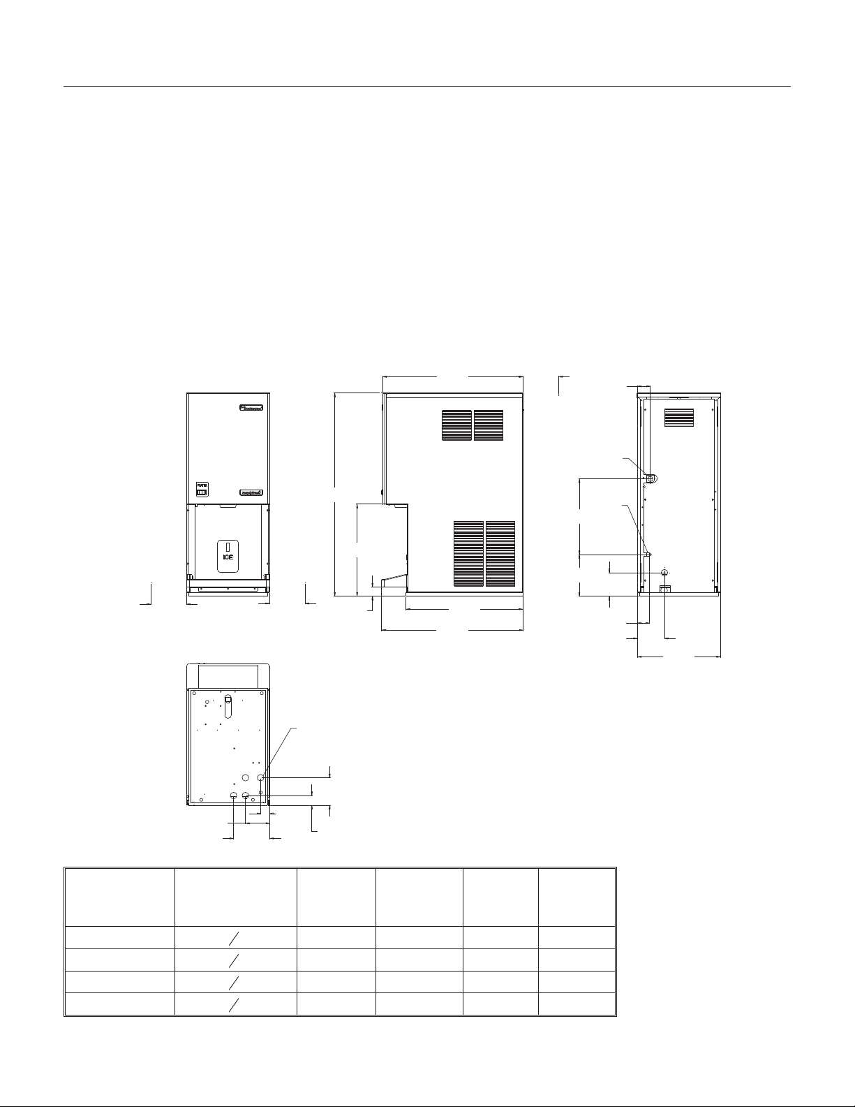
Specifications:
Scotsman ice machines, like the MDT3F or
MDT4F, are designed to be installed indoors, in a
controlled environment. The minimum and
maximum operating conditions are:
Minimum Air Temperature: 50oF.
·
Maximum Air Temperature: 100oF.
·
Minimum Water Temperature: 40oF.
·
Maximum Water Temperature: 100oF.
·
60 Hz voltage may vary between 104 and 126
·
volts.
Water Pressure may vary between 20 and 80
·
psi.
Operating the machine outside these conditions
constitutes misuse and voids the warranty.
Scotsman Ice Systems are designed and
manufactured with the highest regard for safety
and performance. They meet or exceed the
standards of UL, NSF and CUL.
Scotsman assumes no liability or responsibility of
any kind for products manufactured by Scotsman
that have been altered in any way, including the
use of parts and/of other components not
specifically approved by Scotsman.
Scotsman reserves the right to make design
changes and/or improvements at any time.
Specifications and designs are subject to change
without notice.
Specifications:
Model Number Dimensions
W"xD"xH"
MDT4FA-1A 14 x 23
MDT4FA-6A 14 x 23
MDT3FA-1A 14 x 23
MDT3FA-6A 14 x 23
7
x 34¼ 115/60/1 14 oz. 15.1 20
8
7
x 34¼ 230/50/1 14 oz. 7.5 15
8
7
x 34¼ 115/60/1 12 oz. 9.4 15
8
7
x 34¼ 230/50/1 12 oz. 5.3 15
8
Basic
Electrical
Refrigerant
Charge
(R134a)
Min.
Circuit
Ampacity
Max Fuse
Size
November 2008
Page 2
Page 4
MDT3F & MDT4F User Manual
To The Installer:
A professional installation of any product is critical
to the long term satisfaction of the user. The ice
maker-dispenser is designed to be installed either
on a counter, or, using a wall hanging kit, hung
from a wall.
Determine the location from the anticipated use
and any options planned for.
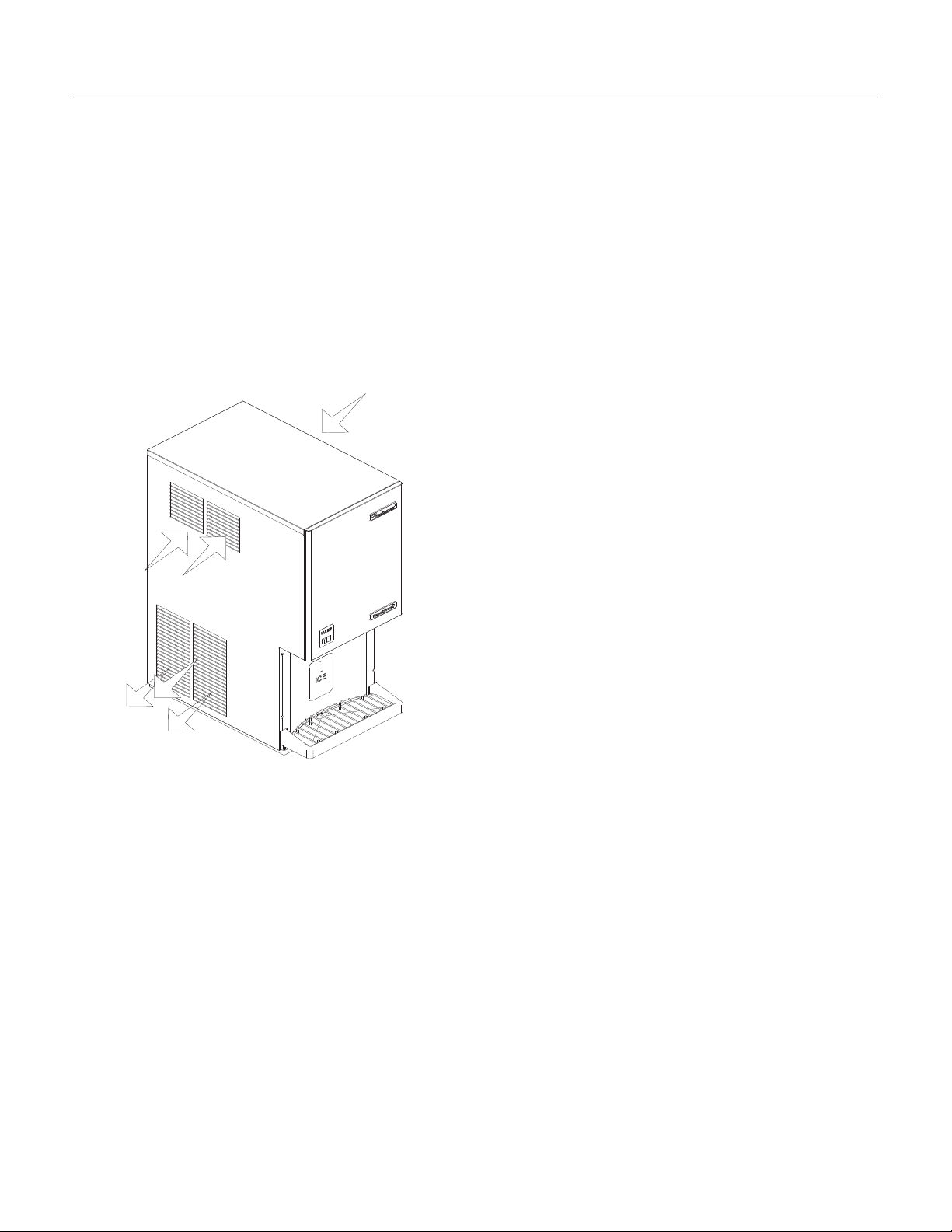
This machine is air cooled and blows air out the
lower left side of the cabinet. Do not install the
machine where the side to side air flow might be
blocked.
Cooling Air Flow
Water Quality:
The quality of the water supplied to the machine
will directly affect the purity of the ice and the
reliability of the machine. While the condition of the
water supplied to a building is normally out of the
control of the user, water can be treated at the
point of use.
There are two major types of water impurities:
suspended solids (those that are carried along with
the water and may be filtered out) and dissolved
solids (those that are part of the water and have to
be treated). A water filter is always a good idea,
but does require regular maintenance to change
the cartridge. In some water conditions, water
treatment may be required. Generally this means a
polyphosphate feeder of some kind. Water
softeners are not recommended.
General Installation:
Place the machine in its final location. Remove the
top, right and left side panels:
1. Remove two screws at the bottom of the front
panel.
Cooling Air
Flow
Warm Air
Exhaust
The machine will require electrical power, water
and a drain. Follow all local codes. Rough in the
utilities before placing the machine into position
(see For The Electrician and For The Plumber).
2. Disconnect wires from water switch.
3. Remove two screws at the front of the top panel.
Lift the top panel and remove it.
4. Remove screws from the sides (top and bottom)
of the side panels and from the splash panel.
5. Pull the side panels back and off the machine.
Plumbing connections may be made thru holes in
the back of the cabinet or thru the base.
·
Route the sink drain to the back of the cabinet.
Route the bin drain to the back panel.
·
Route the electrical power cord from the
junction box inside the cabinet. thru the back
panel .
·
Route the inlet water line thru the back panel or
base to the flare fitting inside the cabinet.
After all plumbing and internal wiring has been
done, replace the side and back panels.
Level the unit front to back and left to right.
The machine does not require sealing to the
counter due to the gasket on the base.
April 2010
Page 3
Page 5
MDT3F & MDT4F User Manual
For The Electrician
Electrical connections:
Check the nameplate for voltage and current
requirements. An electrical cord is not supplied.
Connect the MDT3F or MDT4F to a separate
electrical circuit. Wiring to the machine must
conform to all codes. A licensed electrician may be
required in some situations.
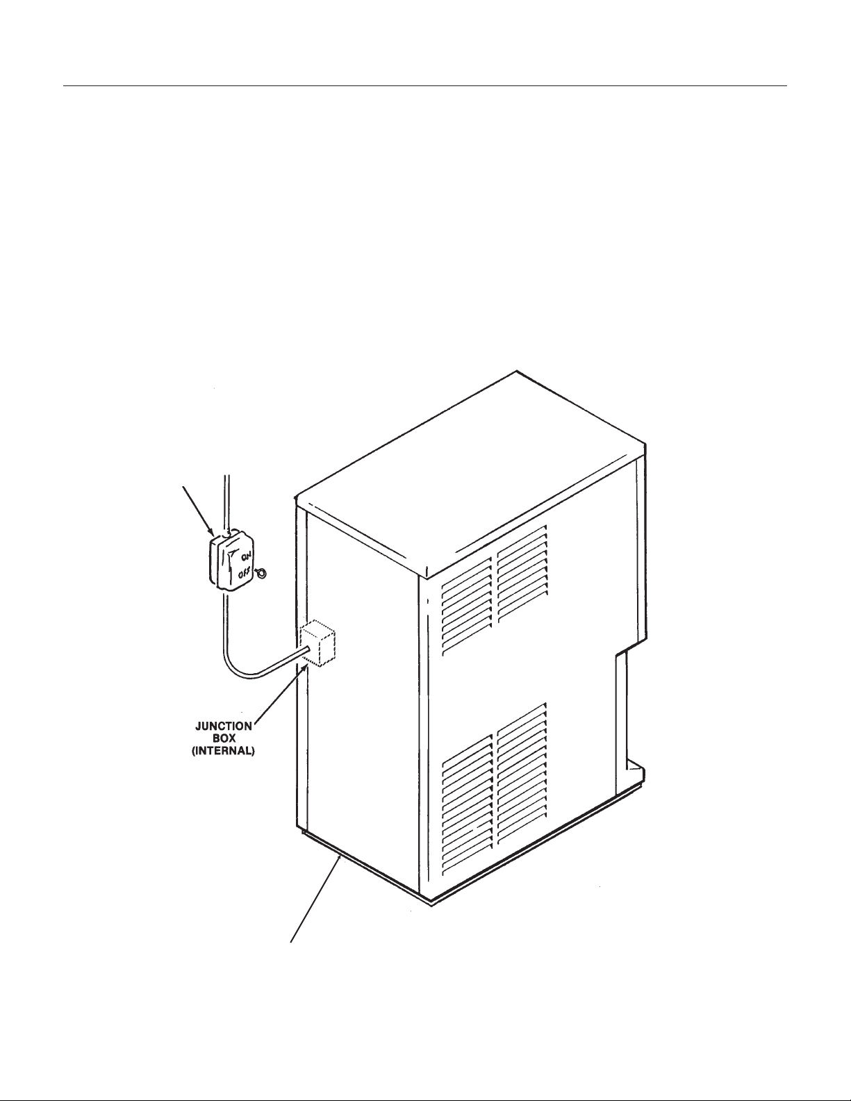
Remove the back panel to make the electrical
connection. The electrical connection is made on
the terminal strip in the junction box inside the
machine. Replace the back panel when the
electrical connections are complete.
FOLLOW ALL APPLICABLE LOCAL, STATE
AND NATIONAL CODES
This Unit MUST BE GROUNDED
Electrical
Power
Remove Back Panel To
Expose Junction Box
November 2008
Page 4
Page 6

MDT3F & MDT4F User Manual
For The Plumber
Drains:
The dispenser requires a gravity drain. The pitch
on the drain tubes must be at least ¼ inch fall per
foot of horizontal run. On long horizontal runs, a
vent at the back of the cabinet will improve
draining, and is recommended.
There are two drains to connect: A sink drain, a
ID plastic tube; and the bin drain, a
5
” ID plastic
8
tube. Install rigid tubing between the machine and
the building drain. Route the drains separately to
the building drain.
7
”
8
Water supply:
Connect cold, potable water to the machine. The
inlet water fitting is a 1/4" male flare located on a
wall inside the cabinet.
A hand valve near the
Water Inlet Fitting - 1/4"
location is
recommended. A water
filter is also a good
idea.
Follow all local codes.
Strainer or
Filter
FOLLOW ALL APPLICABLE LOCAL, STATE
AND NATIONAL CODES
Male Flare
(Inside Cabinet)
Water Supply
Bin and Reservoir
Overflow Drains
Sink Drain
Building Drain
(Typical)
November 2008
Page 5
Page 7

MDT3F & MDT4F User Manual
1.75
26.34
1.75
16.00
16.00
Wall Mount Kit (KWB4):
Contents:
1. Top Case Hanger Bracket: Attaches to the frame
of the dispenser.
2. Top Wall Bracket: Mounts to the wall and
engages the top case hanger bracket to support
the dispenser.
3. Bottom Wall Bracket: Mounts to the wall and
spaces the base of the dispenser away from the
wall.
4. Bottom Fittings Cover: Fastened to the bottom
wall bracket to hide the utility connections.
5. Junction box cover.
1
2
5
Top Wall Bracket:
1. Hold the bracket on the wall where it will be
mounted.
2. Mark the positions of the holes in the bracket
onto the wall.
3. If needed, drill pilot holes for the fasteners.
4. Secure the bracket to the wall with fasteners of
sufficient strength to hold up the dispenser.
Connect all internal utilities. Route tubes and
wires out the bottom.
Junction box cover. Install on the junction box.
Bottom Wall Bracket:
1. Lift up and hang the dispenser from the top wall
bracket.
2. Position the bottom wall bracket so that the
molding on the dispenser base bottoms in the
channel of the wall bracket.
3. Secure the bracket to the wall.
Bottom Fitting Cover:
1. Connect electrical power, water inlet, bin drain
and sink drain of the dispenser thru the bottom of
the case.
4
Installation: Check building wall for the strength
required to support a machine of this weight and
size. Note that if at least 6" of space is not left
above the machine, cleaning and most service of
the machine will require removal of the machine
from the wall mounts. All utilities are to be routed
thru the base. The back panel is not used when
the machine is hung from the wall.
Top Case Hanger Bracket
1. Remove back panel.
2. Place top hanger bracket on the inside of the
frame and position it in line with the pre-punched
holes in the frame.
3. Fasten the bracket to the frame with four¼-20
screws from the kit.
2. Secure bottom fitting cover to the bottom wall
bracket with the four sheet metal screws provided
3
in this kit.
Bottom
Cover
Secure With
Screws
Top Case
Bracket
Wall
Brackets
November 2008
Page 6
Page 8

MDT3F & MDT4F User Manual
Final Check List & Initial Start Up
1. Is the machine located indoors where the
temperature limitations are not exceeded?
2. Is there at least 6" clearance on both sides of
the cabinet for adequate air flow?
3. Is the water supply adequate, and has a shut off
valve been installed?
4. Is the cabinet level?
5. Have all of the electrical and drain connections
been made?
Initial Start Up
1. Remove 2 screws at the bottom of the front
panel.
2. Disconnect wires at water switch.
3. Remove screws and the top and side panels.
4. Open the water supply shut off valve.
5. Watch the water fill the reservoir. Check that
water flows in and fills the reservoir near to the
mark molded into the side of the reservoir. Check
that the float shuts off the water flow when the tank
is full. Check for leaks. Tighten hose clamps as
needed.
6. Plug the unit in or switch on the electrical power.
After about 15 seconds the machine should start.
7. Let the machine operate, listen for any unusual
noises. If needed, reposition tubing & panels to
eliminate vibration.
After the unit has been operating for about 10
minutes, there should be enough ice in the bin to
test the dispense system.
8. Using a container, place in in front of the glass
sensor and below the ice chute. See that ice is
dispensed (the bin drive motor continues to run as
long as the container is in place).
9. Move the water switch (rocker switch on the
front panel) to ON. Place the container in front of
the glass sensor and under the ice chute. Both
water and ice should be dispensed.
10. Pour water into the sink and check that the
drain does not leak but drains the water rapidly.
11. Explain to the user the maintenance
requirements and operation of the machine.
12. Fill out the Warranty Registration and
Customer Evaluation form. Mail it to Scotsman.
13. Leave the service manual with the owner/user
and explain who should be called if service is
needed.
April 2010
Page 7
Page 9

MDT3F & MDT4F User Manual
User Operation
The MDT3F and the MDT4F are automatic ice
vending machines. All either requires is cool air,
clean water and an adequate supply of electrical
power.
To Vend Ice:
Place a container in front of the Touch Free sensor
and below the ice spout. Hold it there until the
container is full of ice. Do NOT overfill the
container or a build up of ice in the sink or a back
up of ice in the spout will occur.
To Vend Ice and Water.
Switch the Water Switch to ON. Place a container
in front of the Touch Free sensor and below the ice
spout. Water and ice will be dispensed into the
container below the spout. Note: The water is NOT
cooled, it is the same temperature as the building
supply water.
Daily Maintenance: Pour hot water into the sink to
flush out any debris or build up. Wipe the cabinet
off, wash the sink and grill to keep minerals from
accumulating.
Caution:
Unless the touch free sensor is
de-activated by pushing the
Cleaning Switch in, ice and/or water
may be dispensed during cleaning.
The Cleaning Switch is a button,
located to the left of the ice chute,
that temporarily shuts off the sensor
for cleanup of the splash panel.
Pushing the button in will disable the
sensor for 2 minutes, pushing the
button in again will return the sensor
to normal operation.
Water
Switch
Glass
Sensor
Touch Free
Disable
Switch
November 2008
Page 8
Page 10

MDT3F & MDT4F User Manual
Mechanical Operation
General:
The machine makes, stores and dispenses ice. It
also dispenses water. The ice making portion of
the machine produces flaked ice at about 32
The ice falls thru a chute into the dispensing bin.
Above the cylindrical bin is a dispense drive motor
and electric eyes. The drive motor is connected to
an ice vane in the bin. When the user holds a
container in front of the glass sensor and below the
ice chute, the dispense drive motor rotates the
vane and the ice. There is a slot in the base of the
bin, located just above the vend spout and glass
filler lever. When the ice moves over that slot,
some of the ice on the bottom of the bin falls thru
the slot, into the chute and fills the container.
ON/OFF Control:
Flaked ice is produced by the ice maker until ice
builds up between the electric eyes. When the
electric eyes can no longer “see” each other, they
send a signal to the control board to shut the
machine off. The refrigeration compressor stops
but the auger drive motor will continue to operate
for about 2 minutes to clear the evaporator of ice.
o
F.
Ice Vending
Dispensing takes place when the touch free
sensor’s infrared beam bounces back to the
sensor from a container placed directly in front of
the sensor and under the ice chute.
When the beam is reflected back, it signals the
circuit board to connect power to the dispense
drive motor, and ice is then moved over the slot in
the base of the bin, where it falls by gravity thru the
chute into the container.
If the Water switch is On, water is also dispensed
at the same time.
Dispensing continues until the beam is no longer
reflected back to the sensor.
Water Control:
Because water is such an important requirement
for making ice, a water level sensor has been
placed in the reservoir. If the water supply to the
machine should fail, the water level sensor will
send a signal to the control board to shut down
the machine.
Refrigeration:
The refrigeration system uses a hermetic
compressor (specifically designed for R-134a),
forced draft air cooled condenser, capillary tube
and vertical flaked ice evaporator. Inside the
evaporator is a slowly rotating auger. The auger is
supported by bearings at each end, and there is a
face-type water seal above the bottom bearing.
The auger is driven by a 1/10 HP direct drive gear
reducer. The auger drive motor has a speed
operated switch on it that will keep the compressor
from operating if the auger motor is not turning at
full speed.
Water System
Water flows from the building supply to the
reservoir and to the electric solenoid valve. Water
from the reservoir is used to make ice. Water the
flows thru the solenoid is dispensed.
Touch Free Sensor
The bin, sink and reservoir overflow all have
drains.
November 2008
Page 9
Page 11

MDT3F & MDT4F User Manual
Maintenance:
Although the ice in this dispenser is completely
untouched, the water and ice vending systems will
need to be periodically sanitized and
de-mineralized. The air cooled condenser will also
need to be kept clean.
Schedule the sanitation, cleaning and
de-mineralization on a regular basis to keep the ice
clean and the machine operating efficiently. Twice
per year is the standard recommendation.
Sanitation and Cleaning
Water System:
This ice machine requires periodic sanitation and
de-mineralization.
1. Vend all ice from the machine.
2. Remove top and right side panels.
3. Unplug or disconnect electrical power.
4. Shut off water supply.
5. Drain reservoir.
6. Mix 8 ounces of Scotsman Ice Machine Scale
Remover and 3 quarts of hot (95
potable water.
Scotsman Ice Machine
Cleaner contains acids.
These compounds may
cause burns. If
swallowed, DO NOT
induce vomiting. Give
large amounts of water
or milk. Call Physician
immediately. In case of
external contact, flush
with water. Keep out of
the reach of children.
7. Pour the water into the reservoir.
8. Wait 15 minutes for the cleaner to dissolve the
minerals inside the evaporator.
9. Plug in the machine or reconnect electrical
power.
10. As the machine operates, pour in the balance
of the cleaning solution.
o
F. -115oF.)
possible sanitizing solution may be obtained by
mixing 1 ounce of household bleach with 2 gallons
of clean, warm (95
13. Unplug or disconnect electrical power.
14. Remove bin top, pour in warm potable water to
melt out any ice.
15. Pull out the vane and bin bottom from the bin.
16. Thoroughly wash the bin’s interior, bin top
interior, spout, ice vane and bin bottom with the
sanitizing solution. Pour some down the bin drain.
17. Reassemble the bin bottom, vane and bin
cover.
18. Wash the sink area with the sanitizing solution
and pour sanitizing solution down the sink drain.
19. Replace all panels and reconnect water and
electrical power.
Air Cooled Condenser:
1. Disconnect electrical power.
2. Remove top panel
3. Remove right and left side panels.
4. Use pressurized air to blow the lint from the
outside of the condenser in towards the fan motor.
A vacuum cleaner hose placed on near the fan
motor should pick up most of the dust. Check for
interior dirt. If needed, use coil cleaner to
de-grease the condenser.
5. Replace all panels and reconnect electrical
power.
o
F.-115oF.) water.
11. Reconnect water supply, operate the machine
for 15 more minutes, then switch it off.
12. Repeat steps 3-11, except substitute a locally
approved sanitizing solution for the cleaner. A
November 2008
Page 10
Page 12

MDT3F & MDT4F User Manual
Inspection:
Photo-Electric Eyes
The photo electric eyes used to “see” the ice build
up in the top of the bin cover must be clean to get
a good “look” at the ice. If clouded by mineral
scale, the eyes will cause the ice machine to shut
off and stay off.
To clean the photo-electric eyes.
1. Remove the top panel.
2. Pull both of the photo-electric eyes out of their
rubber grommets.
3. Wash both eyes with a clean cloth dipped in
Scotsman Ice Machine Scale Remover.
4. Wash the eyes off with clean water.
5. Replace the eyes in the grommets
6. Replace the top panel
Water Level Sensor
The water level sensor may not shut the ice
machine off when the reservoir goes dry if there is
a film of mineral scale on the probe tip.
Clean Photo-Electric
Eyes
1. Remove the top panel.
2. Remove the reservoir cover.
3. Pull the water level probe up and out of the
reservoir.
4. Carefully wipe the tip of the probe with a clean
cloth. Ice machine cleaner may be needed.
Note: The tip is made of glass.
5. Reinsert the water level sensor in the reservoir.
6. Replace the reservoir cover and the top panel.
Coupling
Use the grease zerk on the side of the coupling to
add grease once per year.
Bearing and Water Seal
The top bearing should be checked every time the
machine is cleaned. Unscrew the cap and check. A
visual check can determine if corrosion is
occurring. If worn or corroded, have the bearings
and water seal changed.
Also check for water leaks from the bottom of the
evaporator. If there is a leak, the bearings and
water seal must be replaced. The gear reducer will
also need to be checked for water infiltration.
Clean Water Level
Sensor
Water
Reservoir
April 2010
Page 11
Page 13

MDT3F & MDT4F User Manual
Dispense Area Sanitation
1. The spout may be removed by taking out the
two mounting screws. Wash and sanitize it.
2. The sink grill may be removed for washing and
sanitizing.
3. The sink should be flushed with hot water and
wiped clean with sanitizer.
4. The splash panel requires special attention to
clean it.
Push and release the Cleaning Switch located
·
to the left of the ice spout. This disables the
Touch Free Sensor so the splash panel may be
cleaned without vending ice or water.
Wash the splash panel and wipe with sanitizer.
·
Re-push the clean switch or allow 2 minutes to
·
pass for the Touch Free system to reset.
November 2008
Page 12
Push Touch Free Sensor
Disable Button Before
Wiping Splash Panel
Pour Hot Water Into Sink
Regularly To Keep Drain
Line Open
Page 14

MDT3F & MDT4F User Manual
Service Diagnosis
PROBLEM POSSIBLE CAUSE PROBABLE CORRECTION
No ice is dispensed. No ice in bin due to:
No electrical power
·
Overuse
·
Water supply turned off
·
Bin controls dirty
·
Water sensor dirty
·
Control system malfunction
·
Auger drive motor open
·
Centrifugal switch open
·
Auger does not turn
·
No refrigeration
·
Ice in bin, but will not dispense:
Drive motor does not turn
Vend system does not work
·
·
Dispense motor open
·
Dispense output shaft broken
Ice in bin, motor turns vane.
Ice jammed up
·
Users held cup against
dispense spout and jammed
unit.
·
Bin bottom slot not over spout
·
Ice will not slide down bin wall,
bin out of round.
·
Wet ice in the bin from high
water level or high suction
pressure
Check/restore power
Recheck ice needs vs. machine
capacity.
Check water filter/hand valve/float
valve
Check & clean bin control (electric
eyes)
Check & clean water sensor
Check control system
Check auger drive motor
Check centrifugal switch
Check coupling & gear reducer
Check refrigeration system
Check/replace vend system
Check that cleaning switch has
been released.
Check/replace dispense motor
Check/replace output shaft
Advise owner/manager to instruct
users.
Check bin bottom position
Check bin interior wall for rough
texture or out of round.
Check water level, check suction
and discharge pressures
November 2008
Page 13
Page 15

MDT3F & MDT4F User Manual
Service Diagnosis: Circuit Board
1
2
3
Explanation of Indicator Light Position On
Board
On at all times when the master switch is ON and machine is
connected to electrical power.
On when ice level is low (unit making ice).
Normal 6 minute off/delay start. To prevent short cycling, the
machine will not restart after any shut off (except power to the
board) until 6 minutes have passed.
On when water level is low in the reservoir.
To check the electrical system, first check the lights on the circuit board.
1. Remove the top panel.
1 Power,
2 Bin Empty,
3 Off Timer,
4 No Water,
4
Name and Meaning of
Light or Reset
ON = Normal
ON = Needs Ice
ON = Unit cycling off
ON = Trouble
2. Remove the left side panel.
3. Remove the control box cover.
November 2008
Page 14
Page 16

SCOTSMAN ICE SYSTEMS
775 Corporate Woods Parkway, Vernon Hills, IL 60061
800-533-6006
www.scotsman-ice.com
17-3281-01 Revised April 2010
 Loading...