

Page 1

HD356 Service Parts
This parts list contains the service parts for the
HD356 dispenser.
Use caution when ordering parts. Double-check
the model number to be certain that the parts
ordered are the ones for that machine.
Table Of Contents
Panels ..............................................Page 2
Cabinet .............................................Page 3
Lower Cabinet Parts ......................................Page 4
Hopper and Rotor ........................................Page 5
Dispensing Components ....................................Page 6
Gear Drive ............................................Page 7
Control Box ...........................................Page 8
Coin and Card Mechanisms ..................................Page 9
Wiring Diagrams ....................................... Page 10
June 1998
Page 1
Page 2
10
HD356 Service Parts
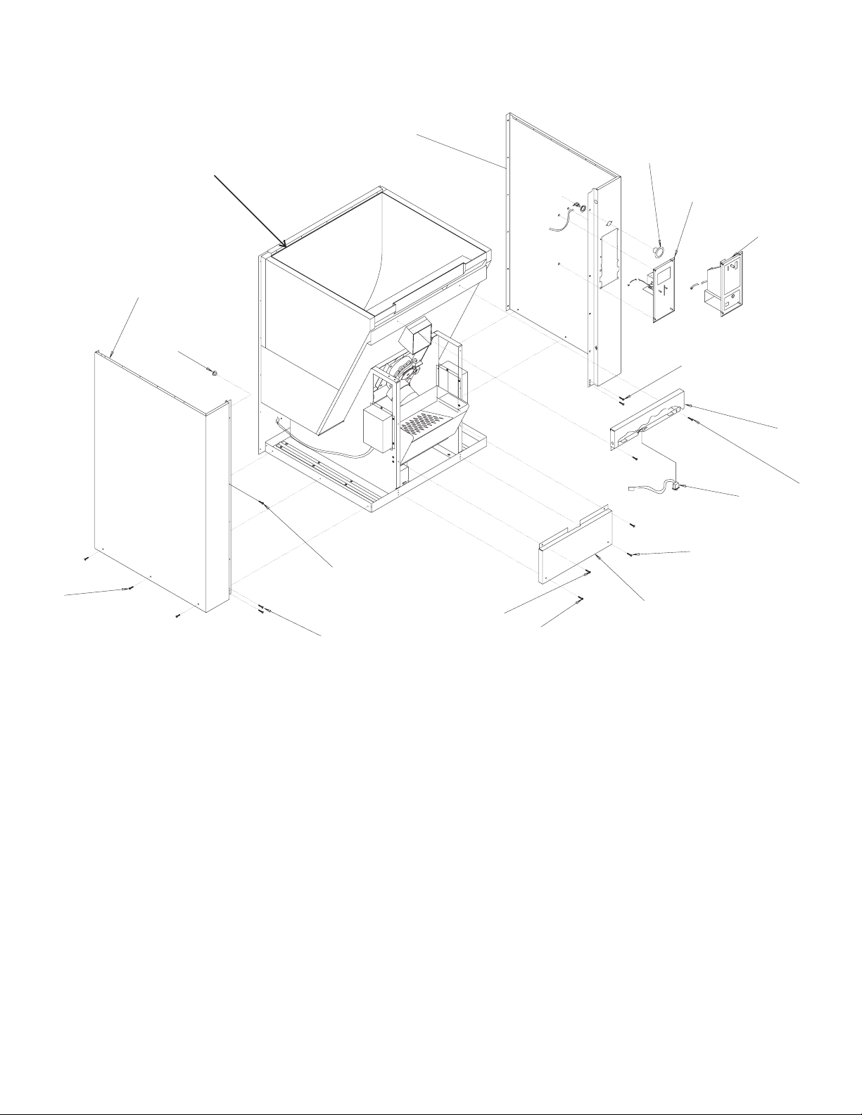
Panels
12
1
13
2
3
11
4
5
6
Item Part
Number Number Description
1 02-3773-01 Push button switch
2 KCARD Card kit
3 02-3114-01 Coin mech
4 03-1531-01 Screw
5 A3
2625-015 Grey upper front panel
A3
2625-002 SS upper front panel
6 03-1638-03 Screw
7 12-1276-01 Switch
8 03-1419-28 Screw
7
8
6
6
4
Item Part
8
9
6
Number Number Description
11 12-0629-01 Strain relief
12 A37393-015 Grey right side panel for
coin or card kit
A37393-002 SS right side panel for
coin or card kit - A series
A37637-001 SS right side panel for
coin or card kit - C series
A37393-016 Grey right side panel for
button only A series
9 A32620-015 Grey panel, bottom
A32620-002 SS panel, bottom
10 A32622-015 Grey left side panel
A32622-002 SS left side panel - A series
A37638-001 SS left side panel - C series
A37393-003 SS right side panel for
button only A series
A37637-002 SS right side panel for
button, C series
13 A34726-015 Grey back panel
A34726-015 SS back panel
January 2000
Page 2
Page 3
22
23
HD356 Service Parts
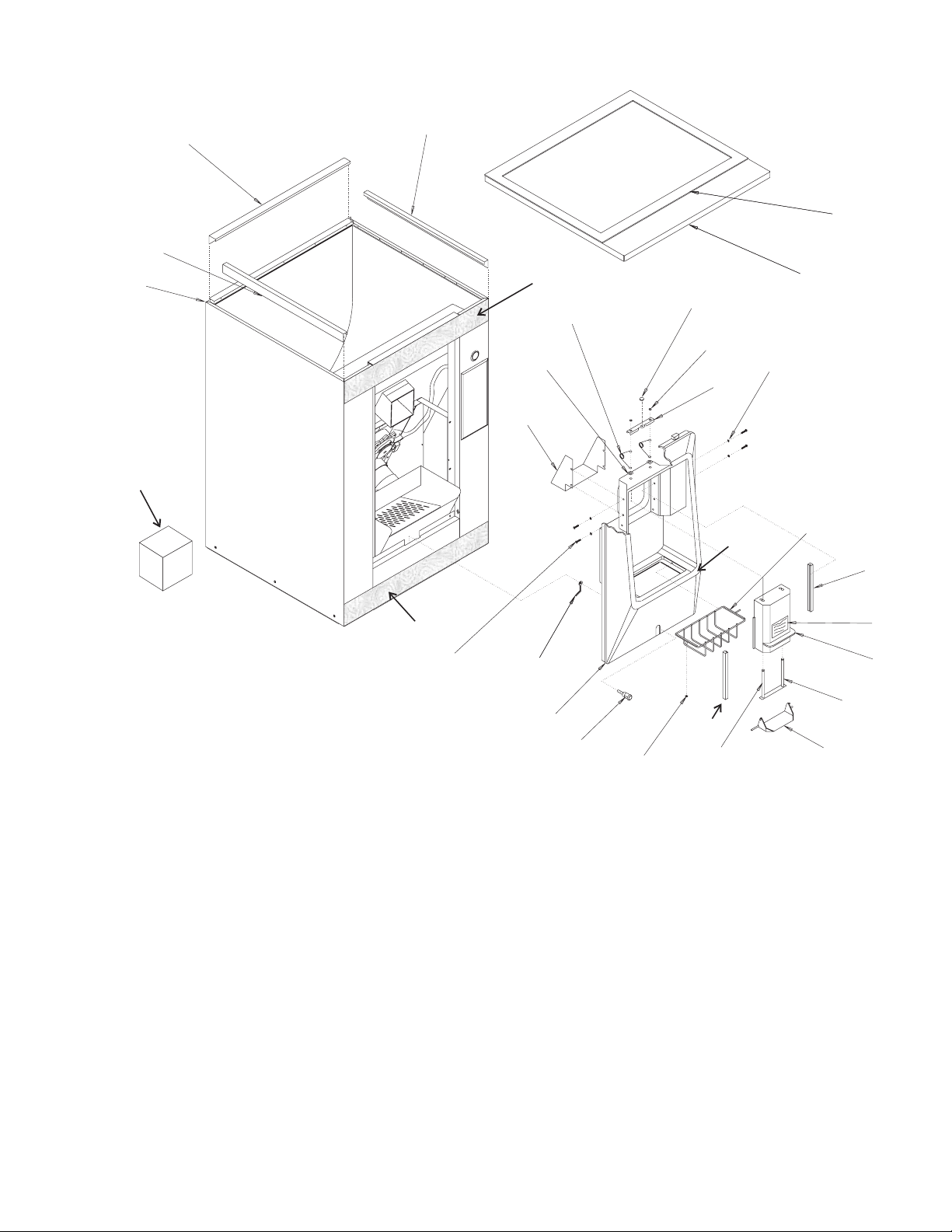
Cabinet
22
1
Top
Edge
26
24
Item Part
Number Number Description
1 19-0503-04 Gasket, order 9 units
2 A36735-001 Top panel, A series
02-3839-01 Top panel, for C series
3 A25377-001 Shield
4 03-1407-07 Washer
5 02-2097-01 Spring
6 13-0876-01 Bumper
7 03-1539-03 Retainer
8 A36487-001 Bar
9 03-1407-02 Washer
10 17-2604-01 Button disp. decal
11 02-3018-01 Grill
12 02-3137-01 Track
13 KIB200 Optional ice baffle kit
14 02-1994-20 Dispensing hood & label
15 A23674-001 Return assembly
21
25
6
5
7
4
3
20
19
18
Item Part
17
8
12
Food Grade
Lube Here
9
13
Number Number Description
16 02-1995-01 Ice chute gate
17 03-1651-01 Nut
18 A35618-001 Lock Kit
02-3263-01 Key
19 02-2901-04 Sink
20 no number Latch, part of item 18
21 03-0727-09 Thumb screw
22 A32818-001 Side bracket
23 A32817-001 Rear bracket
24 17-2598-02 Bottom label
25 17-2598-01 Top label
26 KLP7 Leg kit (4 legs)
2
11
12
10
14
15
16
January 2000
Page 3
Page 4
HD356 Service Parts
Item Part
Number Number Description
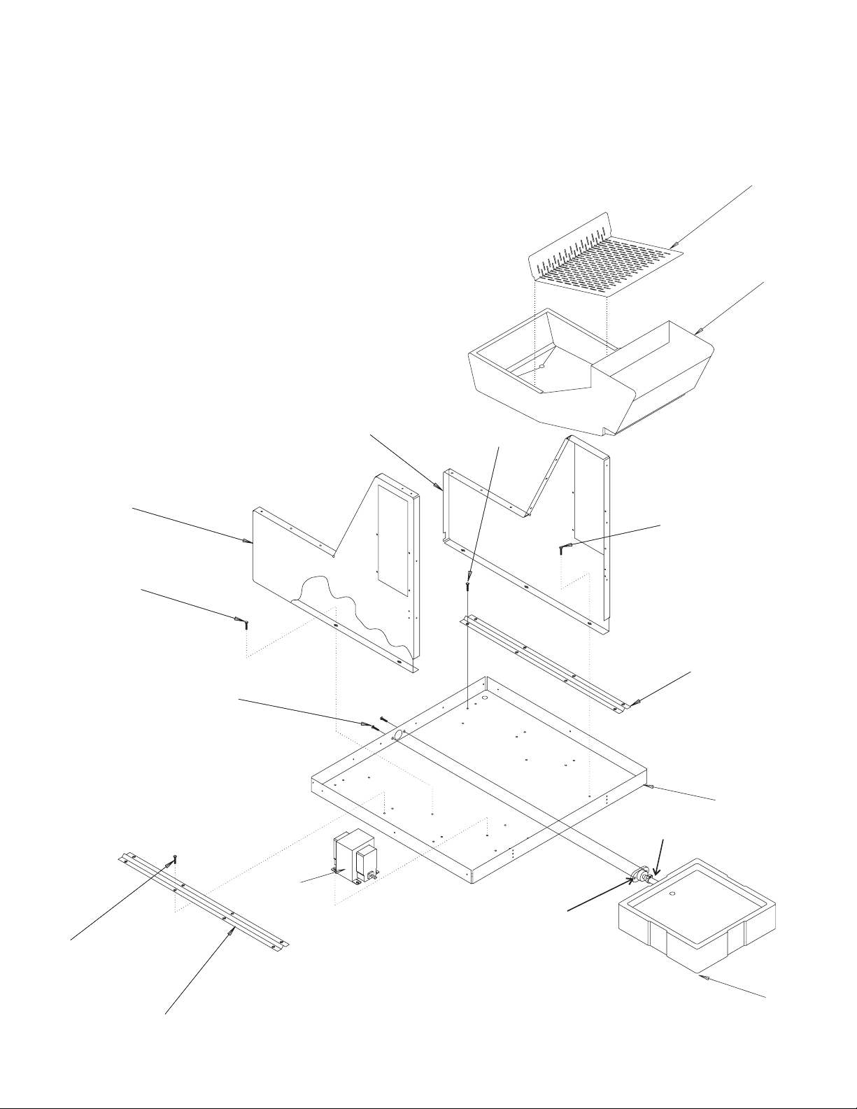
Lower Cabinet Parts
1 03-1645-01 Screw
2 A32616-015 Brace
3 A34727-015 Base
4 A38021-001 Drain pan & fitting
5 12-2333-21 50 Hz transformer
6 03-0571-00 Screw
7 A32617-015 Bin support left
8 A32617-016 Bin support right
9 A35416-001 Drain chute
10 A35542-001 Dam screen
11 02-3692-21 Drain fitting
12 A33203-001 Drain tube
02-2814-08 Hose clamp
7
10
9
8
1
1
1
2
6
3
12
5
11
1
4
2
October 2001
Page 4
Page 5
Ins.
HD356 Service Parts
Hopper and Rotor
4
2
1
3
Ins.
5
9
10
8
6
11
Ins.
Ins.
Item Part
Number Number Description
7
Ins.
12
13
21
20
Ins.
19
14
15
16
17
18
Ins.
Item Part
Number Number Description
1 A37380-001 Rotor channel
2 02-3221-01 Rotor nut
3 02-3768-01 Drive block
4 A37343-002 Rotor
5 03-1725-01 Washer
6 03-1403-72 Screw
7 03-1417-09 Washer
8 02-3754-20 Shaft and housing
9 02-2809-01 Drain top
10 13-0617-11 O ring
11 02-2911-02 Storage bin
12 03-1645-01 Screw
13 A32653-015 Grey retainer
14 12-2175-01 Terminal block
15 03-1404-13 Screw
16 A32644-015 Gear motor support
17 15-0575-01 Coupling
18 A28155-021 Gear and motor
19 03-1406-12 Hex nut
20 03-1410-05 Lockwasher
21 02-2692-01 Drain
June 1998
Page 5
Page 6

HD356 Service Parts
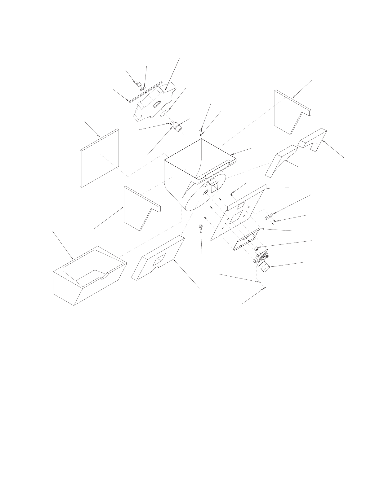
Dispensing Components
1
2
3
4
5
6
5
4
3
2
1
7
8
9
Item Part
26
Number Number Description
1 03-1516-01 Retaining ring
2 02-2026-01 Cup closure
3 03-1408-27 Special washer
4 02-2027-01 Flinger
5 02-2186-01 Bearing cup
02-2186-02 Bearing cone
6 02-3754-20 Bearing Housing,
includes shaft and coupling
7 02-3757-20 Shaft and coupling kit
8 03-1410-04 Lockwasher
9 03-1405-15 Screw
10 A29732-001 Bracket, double cam
11 03-1403-18 Screw
12* A37852-001 Cam #2, bottom - by case
13 A29733-001 Spacer
14* A37851-001 Cam (top) all
15 03-1410-07 Lockwasher
10
20
14
15
16
20
19
11
17
12
13
18
18 03-1405-03 Screw
19 03-1403-09 Screw
20 12-2365-01 Cam switch
21 03-0886-00 Speed nut
*Replace items 12 and 14 as a set in HD356s
built prior to date code 05R.
16 03-1406-03 Nut
17 03-1410-03 Lockwasher
October 2001
Page 6
Page 7
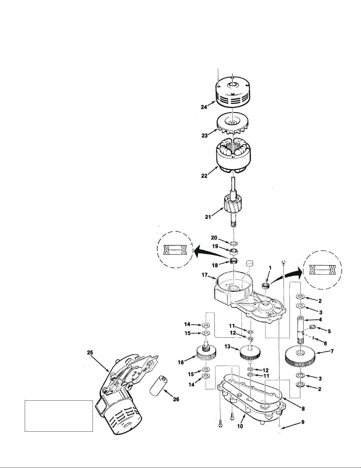
HD356 Service Parts
Gear Drive
Item Part
Number Number Description
1 02-1503-00 Grease Seal (2)
2 03-1408-21 Washer
3 03-1408-04 Washer
4 02-2446-01 Output shaft
5 03-1515-03 Retaining ring
6 03-1602-01 Woodruff key
7 02-2444-01 Output gear
8 02-1505-00 O-Ring
9 03-0774-11 Roll pin
10 A28167-001 Gear case assembly
11 03-1408-39 Washer
12 03-1408-40 Washer shim
13 02-2441-01 Second gear, third pinion
14 03-1408-01 Washer
15 03-1408-38 Washer
16 02-2448-01 First gear, second pinion
17 A28189-001 Gear box cover
18 02-1504-00 Grease seal
19 02-1501-00 Bearing
20 03-1408-08 Washer
21 A28160-002 Rotor assembly
22 12-2036-01 Stator (115/60/1)
23 A28168-001 Cooling fan
24 A38487-020 Motor housing
25 A28155-021 Complete gear Motor
without cams or bracket.
26 18-3701-01 Capacitor
Note: 16 oz. can of
grease is P/N
19-0472-20. Gear case
capacity is 12 oz.
September 2005
Page 7
Page 8

HD356 Service Parts
Control Box
1
8
6
2
1
2
3
5
3
7
4
Item Part
Number Number Description
1 12-1213-10 Snap bushing
2 03-1531-08 Screw
3 12-2114-01 Terminal strip
4 12-2090-02 Relay
5 12-2836-01 Transformer 115 to 24
6 12-2631-01 Recycling timer
8 03-1404-14 Screw
9 12-0426-01 Toggle switch
10 A35398-015 Control box cover (not shown)
February 2001
Page 8
Page 9

HD356 Service Parts
Coin and Card Mechanisms
02-3114-01 - Complete coin mech
KCARD
Item Part
Number Number Description
1 02-3114-20 Lock kit (includes key & lock)
2 02-3114-21 Coin return kit (solenoid)
3 02-3114-22 Cash box
4 02-3114-23 Coin switch
5 17-2614-01 Label
Item Part
Number Number Description
1 A29708-003 Cover plate, SS
Relay Box for Coin Mechanism Models
A29708-015 Cover plate, Grey
2 12-2450-01 Microswitch
3 17-2144-01 Label
Item Part
Number Number Description
1 No number Relay box
2 12-0876-00 Cam switch
3 12-2090-02 Relay
4 12-2175-01 Terminal block
5 03-1403-08 Screw
6 12-1213-10 Bushing
7 12-0426-01 Switch
8 12-2187-02 Plug & harness
September 2005
Page 9
Page 10

C
CAM
SWITCH
#1
HD356 Service Parts
Schematic Diagram - Button Dispensing
H
RELAY C
4
7
VEND SWIT
RELAY C
A
321
TIMER
TRANSFORMER
B
MASTER
SWITCH
RELAY C
6
9
RUN
CAPACITOR
June 1998
Page 10
GEAR
MOTOR
DOOR SAFETY
SWITCH
N
Page 11

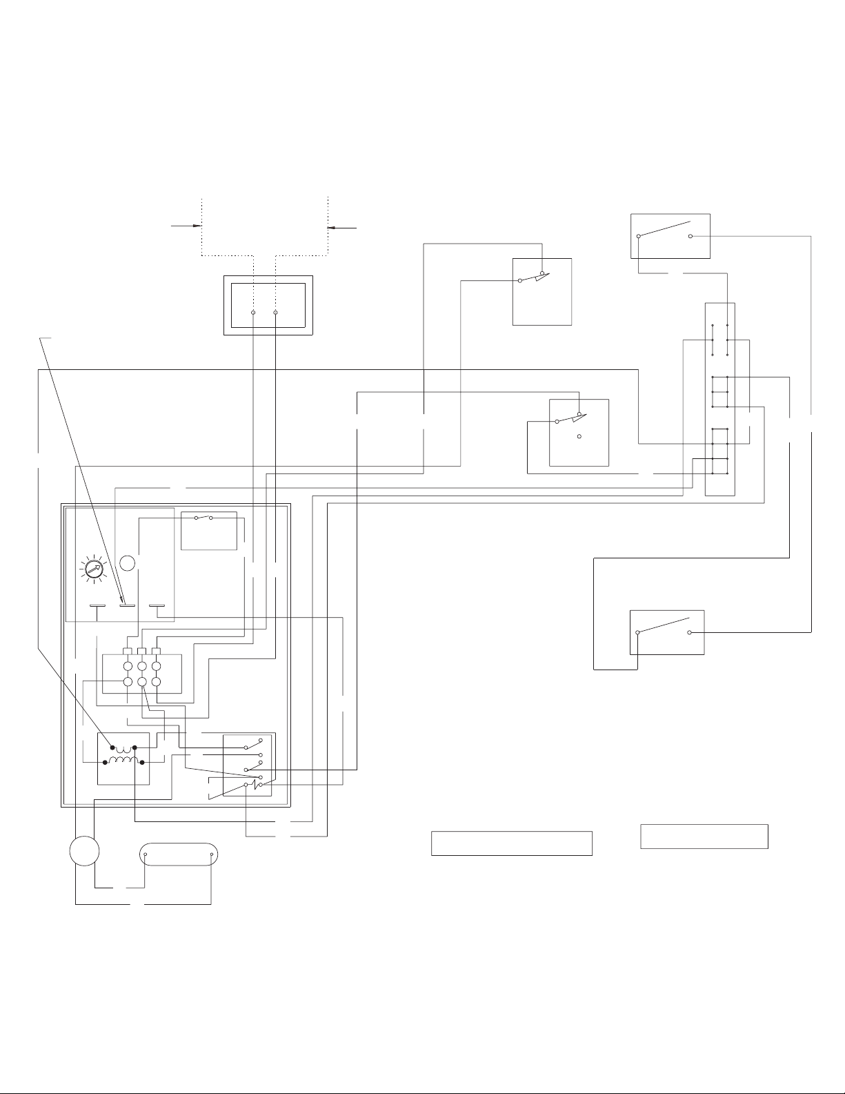
HD356 Service Parts
Wiring Diagram - Button Dispensing
PIGGYBACK CONNE CTION TO BE POSITIONE D
AWAY FROM OTHER CONNECT IONS ON TIMER
O
TIMER
R
1
2
3
SEE NAMEPLATE FOR
VEND
SUPPLY VOLTAGE AND
MAXIMUM FUSE SIZE
NO
GY
11 1
JUNCTION BOX
SWITCH
NO
SWITCH
DOOR SAFETY
GY
BN
CAM #1
BU
NO
O
NC
SWITCH
BN
R
SWITCH
MASTER
R
BK
W
20
10
O
TERMINAL
BLOCK
W
BK
W
RUN
CAPACITOR
R
RELAY C
3
9
BK
BU
6
1
7
4
A
B
BK
GEAR
MOTOR
24V
115V
TRANSFORMER
BU
BU
USE COPPER CONDUCTORS ONLY
Y
MODEL HD356 B
(-01)
Y
V
17-2619-01
THIS UNIT MUST BE GROUNDED
June 1998
Page 11
Page 12

HD356 Service Parts
Schematic Diagram - Coin Vending
EMPTY LIGHT
65
CAM SWITCH
#2
RELAY D
4
COIN SWITCH
2 3
RELAY D
96
FREE VEND
CAM SWITCH
#1
RELAY C
7
4
7
VEND SWITCH
1
COIN BLOCK
RELAY D
A
RELAY C
A
B
B
MASTER
SWITCH
RELAY C
9
123
6
RUN
CAPACITOR
TIMER
TRANSFORMER
GEAR
MOTOR
DOOR SAFETY
SWITCH
N
June 1998
Page 12
Page 13

Wiring Diagram - Coin Vending
SEE NAMEPLATE FOR
SUPPLY VOLTAGE AND
MAXIMUM FUSE SIZE
HD356 Service Parts
JUNCTION BOX
NO
VEND
SWITCH
EMPTY LIGHT
GY
NO
LAMP
GY
PIGGYBACK CONNECTIO N TO BE POSITIONED
AWAY FROM OTHER CONNECTION S ON TIMER
O
TIMER
R
1
2
O
W
BK
BK
24V
W
115V
TRANSFORMER
GEAR
MOTOR
RUN
CAPACITOR
BU
BU
R
3
TERMINAL
BLOCK
SWITCH
MASTER
R
BK
SWITCH
11 1
DOOR SAFETY
BN
BU
CAM #1
NO
NC
SWITCH
Y
BK
BN
20
10
R
BK
W
COIN BLOCK
O
(WHEN APPLICABLE)
SOL
R
BN
R
Y
RELAY C
3
9
6
1
7
4
A
BU
B
FREE
VEND
RELAY D
R
3
6
9
1
4
7
B
A
BU
BU
O
Y
OMITTED ON
KCM 20 0 &
KKM 200
R
R
Y
V
BN
1
11
10
BN
20
Y
BN
W
Y
O
MODEL HD356 N
USE COPPER CONDUCTORS ONLY
SWITCH
COIN MECH.
VEND SWITCH
NO
SWITCH
CAM #2
THIS UNIT MUST BE GROUNDED
June 1998
Page 13
17-2620-01
Page 14

C
HD356 Service Parts
Schematic Diagram - Card Vending
CAM
SWITCH
#1
VEND SWITCH
RELAY C
4
7
123
ARDSWITCH
TIMER
RELAY C
A
B
L
MASTER
SWITCH
RELAY C
6
9
RUN
CAPACITOR
June 1998
Page 14
TRANSFORMER
GEAR
MOTOR
DOOR SAFETY
SWITCH
N
Page 15
HD356 Service Parts
Wiring Diagram - Card Vending
PIGGYBACK CONNE CTION TO BE POSITIO NED
AWAY FROM OTHER CONNECT IONS ON TIMER
O
TIMER
R
1
2
3
SEE NAMEPLATE FOR
VEND
SUPPLY VOLTAGE AND
MAXIMUM FUSE SIZE
JUNCTION BOX
SWITCH
NO
SWITCH
NO
GY
111
DOOR SAFETY
BN
CAM #1
BU
NC
NO
O
O
GY
SWITCH
BN
R
SWITCH
MASTER
R
BK
W
20
10
CARD
O
TERMINAL
BLOCK
W
BK
BK
TRANSFORMER
24V
115V
R
RELAY C
W
BK
BU
3
9
6
1
7
4
A
B
Y
GEAR
MOTOR
RUN
CAPACITOR
V
BU
BU
USE COPPER CONDUCTORS ONLY
SWITCH
Y
MODEL HD356 C
17-2621-01
THIS UNIT MUST BE GROUNDED
June 1998
Page 15
Page 16

HD356 Service Parts
50 Hz Wiring and Schematic Diagram
17-2619-06
VEND SWITCH
CAM SWITCH
SWITCH
N
TRANSFORMER
115 V
L
230 V
B
RELAY C
A
TIMER
4
7
RELAY C
#1
321
SWITCH
DOOR SAFETY
TRANSFORMER
GEAR
MOTOR
RUN
CAPACITOR
6
9
RELAY C
MASTER
L
THIS UNIT MUST BE GROUNDED
L
GY
O
111
NO
10
20
GY
VEND
SWITCH
BN
(-06)
NO
NC
NO
SWITCH
SWITCH
DOOR SAFETY
CAM #1
MODEL HD356 B
BU
BN
JUNCTION BOX
W
BK
R
SEE NAMEPLATE FOR
SUPPLY VOLTAGE AND
MAXIMUM FUSE SIZE
SWITCH
MASTER
TRANSFORMER
R
TERMINAL
3
R
2
O
TIMER
PIGGYBACK CONNECTI ON TO BE POSITIONED
AWAY FROM OTHER CONNECTION S ON TIMER
1
O
BLOCK
Y
Y
6
4
3
1
9
7
RELAY C
BK
R
W
BK
24V
115V
TRANSFORMER
W
BK
V
B
A
BU
RUN
CAPACITOR
BU
BU
GEAR
MOTOR
USE COPPER CONDUCTORS ONLY
June 1998
Page 16
 Loading...