

Page 1

HD22 and HD30 Service Parts
This is the list of service parts and wiring diagrams
for all versions of these two hotel dispensers.
Pay close attention to the voltage and/or cycles to
be sure of ordering the correct part.
Table of Contents
Front and Top Panels ······································· Page 2
HD30B & HD22B Front Panel ··································· Page 3
HD30N and HD30W Front Panel & Related Parts ························ Page 4
Side, Back and Interior Panels ·································· Page 5
Dispensing Components ····································· Page 6
Ice Chute Mechanism ······································· Page 7
Ice Catch Pan ··········································· Page 8
Control Box ············································ Page 9
Wiring Diagram, 115 volt, 60 Hz Basic and Water Station····················· Page 10
Schematic Diagram, Basic and Water Station Models ······················ Page 11
Wiring Diagram, 230 volt, 50 Hz Basic ······························ Page 12
Wiring Diagram for Coin Mechanism Model ···························· Page 13
Schematic Diagram for Coin Mechanism Model ························· Page 14
Page 2
HD22 and HD30 Service Parts
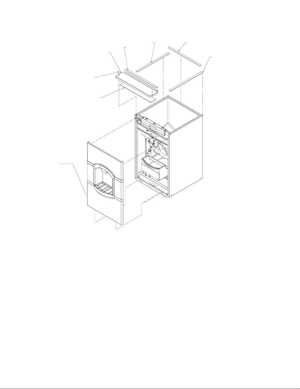
Front and Top Panels
2
3
4
5
1c
1b
1a
1b
Item Part
Number Number Description
1 19-0503-04 Gasket tape, order by ft.
1a Use 27.5” for HD30, 19.5” for HD22
1b Use 27.88”
1c Use 27.25” for HD30, 19.25” for HD22
2 02-3997-01 HD30 top panel
02-3997-03 HD22 top panel
3 03-1735-01 Top panel screw
4 02-3998-01 HD30 panel insulation
02-3998-02 HD22 panel insulation
5 A38318-021 HD30B or HD30W front
panel with side flanges
A38318-023 HD30N front panel
with side flanges
A38319-021 HD22 front panel
with side flanges
September 2003
Page 2
Page 3
HD22 and HD30 Service Parts
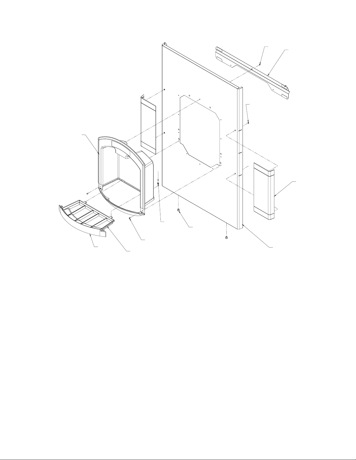
HD30B & HD22B Front Panel
11
1
3
2
4
10
Item Part
Number Number Description
1 03-3836-01 Screw
2 A38357-001 HD30 stiffener
A38357-002 HD22 stiffener
3 03-1731-02 Retainer
4 02-3973-01 HD30B side flange
02-3973-02 HD22 side flange
5 A38318-021 HD30 Front panel*
A38319-021 HD22 Front panel*
6 12-1213-04 Snap bushing
7 03-1404-12 Screw
9
7
6
8
5
Item Part
Number Number Description
11a 02-3971-01 HD22, HD30B, HD30N
dispense housing
11b 02-3971-03 HD30W dispense
housing
* includes items 1 thru 4
8 03-1531-01 Screw
9 19-0503-11 Foam gasket, 6” per side
10 02-3972-01 Grill
September 2003
Page 3
Page 4
HD22 and HD30 Service Parts
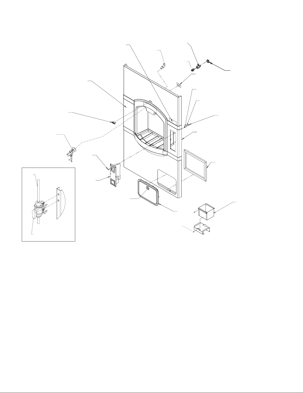
HD30N and HD30W Front Panel & Related Parts
21
20
19
5
18
6
17
4
1
2
8
9
10
12
13
3
11
14a, 14b
7
Item Part
Number Number Description
1 16-0835-01 Water inlet fitting
2 16-1039-01 Straight connector
3 03-1394-01 Pal nut
4 16-1104-01 Male elbow connector
5 02-3990-01 Water faucet
6 13-0895-01 Tubing, order per ft
7 16-1105-01 Shut off valve
8 A38462-001 Indicator light backing
9 03-1407-02 Washer for coin mech
10 03-1410-07 Lockwasher
11 03-1406-04 Hex nut (8-32)
16
14
15
12 02-3973-05 Right side flange for coin
mech model
13 01-1295-01 Door shim
14 12-2896-02 Door and lock
14a 12-2896-26 Lock and key
14b 12-2896-27 Key
15 03-1531-01 Coin box screw
16 A38438-001 Coin box
17 12-2896-01 Coin mechanism
12-2896-25 Coin switch
18 12-2896-03 Mounting screw
19 12-2908-01 Ready light
20 02-3973-01 HD30 left side flange
21 17-2970-01 Coin mech label
November 2005
Page 4
Page 5
19
HD22 and HD30 Service Parts
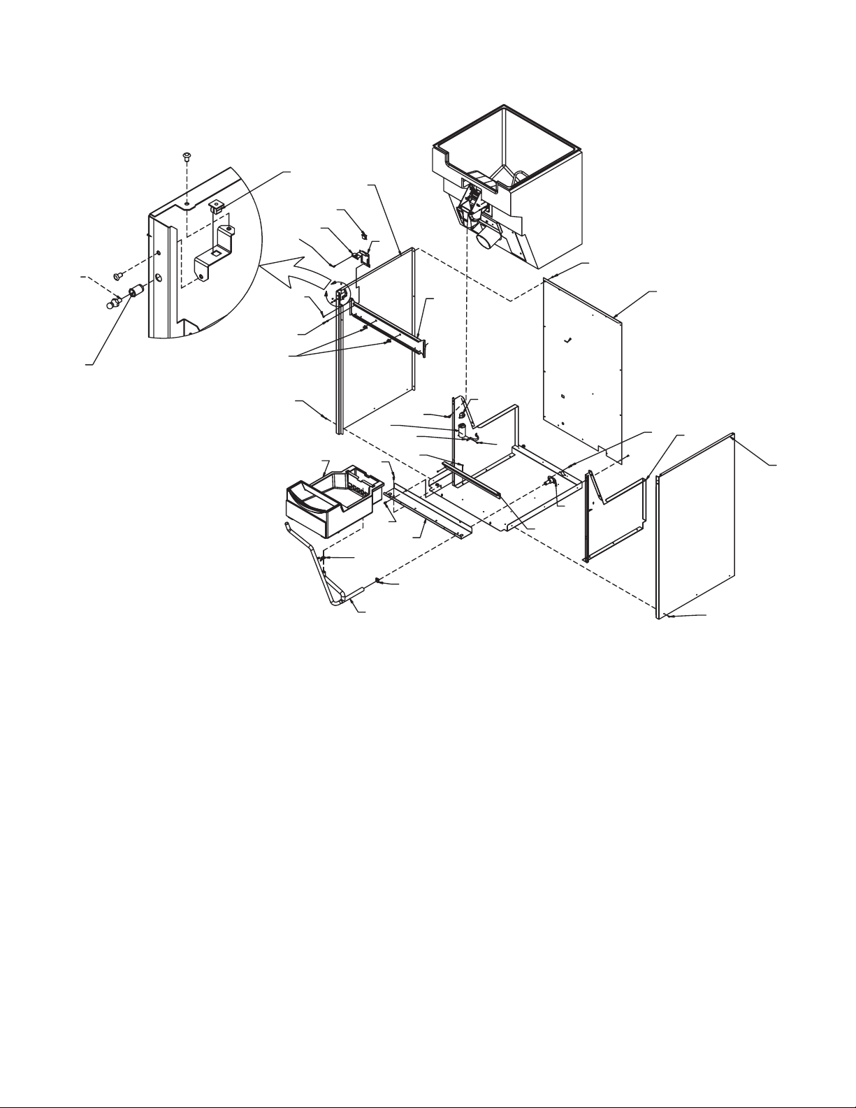
Side, Back and Interior Panels
18
17
16
15
1
1
1
15a
1
22
2
20
Item Part
Number Number Description
1 03-1531-01 Screw
2 A38321-001 HD30 back panel
A38322-001 HD22 back panel
14
1
13
10
23
9
12
9
24
1
9
8
11
21
4
1
6
7
12 02-3979-01 Drain hose
13 A38316-021 Drain pan, assembled
14 02-3011-01 Wire clamp (coin mech)
15 A38435-002 Switch plate top
15a A38435-001 Switch plate
5
1
3
3 A38320-022 Right side panel,
includes mounting hardware
4 03-0571-01 Screw
5 A38325-002 Bin support, right
A38325-001 Bin support, left
6 02-3692-23 Drain fitting
7 A38348-001 Catch pan support
8 A38362-001 HD30 base stiffener
A38362-002 HD22 base stiffener
9 03-1645-01 Screw
10 02-3791-01 Hose clamp
11 02-2814-09 Hose clamp
16 12-1276-01 Switch, interlock
17 A38320-021 Left side panel, includes
mounting hardware
18 03-3804-01 Plastic nut
19 03-1733-01 Strike (ball stud)
20 03-1734-01 Insert
21 13-0666-00 Terminal cover
22 A38333-001 HD30 support bracket
A38333-002 HD22 support bracket
23 18-1902-52 Motor capacitor
24 A35971-001 Strap
November 2005
Page 5
Page 6

HD22 and HD30 Service Parts
Dispensing Components
1
22
21
20
19
8
17
16
18
23
2
3
4
5
6
7
8
9
15
14
Item Part
Number Number Description
1 03-3837-01 Hitch pin
2 02-3989-01 Sweep arm
3 02-3040-01 Dispense rotor
4 A38145-001 Hub plate
5 A38314-001 HD30 bin assembly
A38314-002 HD22 bin assembly
6 13-0940-01 Insulation pad
7 03-3841-02 Loop clamp
8 03-1404-12 Screw
9 13-0939-01 Insulation for hub
10 12-2897-01 Dispense gearmotor,
13
dual voltage
12
10
11
11 03-1731-02 Retainer
12 03-1731-04 Cupped washer
13 03-1731-03 Spring
14 03-3838-02 ¼ turn stud
15 03-1645-01 Screw
16 A38342-001 Mounting plate
17 03-1531-01 Screw
18 A34760-001 Hub
19 A38446-001 Switch guard
20 02-3965-01 Spout
21 02-4000-01 Gasket
22 19-0503-09 Gasket, 4” each end
23 A38341-002 Bin door
September 2003
Page 6
Page 7

HD22 and HD30 Service Parts
Ice Chute Mechanism
8
3
4
5
1
2
3
Item Part
Number Number Description
1 A38455-001 Clip
2 03-1531-01 Screw
3 02-3964-01 Bracket
4 02-3963-01 Door lock
5 02-3962-01 Door
6 02-3970-01 Wire
7 02-3961-01 Dispense chute
8 12-2879-01 Vend switch
6
7
September 2003
Page 7
Page 8

HD22 and HD30 Service Parts
Ice Catch Pan
10
1
2
2
3
4
5
6
7
9
8
Item Part
Number Number Description
1 A38332-001 Screen
2 03-1404-12 Screw
3 02-2809-02 Drain top
4 A38316-021 Complete assembly as
shown
5 02-4193-01 Flat washer
6 02-3201-01 Drain bottom
7 16-1099-01 Drain fitting
8 A38454-001 Drain pan bracket
9 02-3999-01 Foam pad
10 A38447-001 Drain guard
2
2
January 2006
Page 8
Page 9

HD22 and HD30 Service Parts
Control Box
1
2
3
10
4
Item Part
Number Number Description
1 12-2948-01 Coin mech timer*
2 03-1419-16 Screw
3 part of item 1
4 03-1531-01 Screw
5 03-3841-01 Loop clamp
6 12-1213-10 Snap bushing
4
2
5
6
4
7
8
9
Not shown
11 12-2880-01 60 Hz harness, basic
and water
12-2891-01 Coin mech harness
12-2904-01 50 Hz harness
12 12-1638-20 115 volt power cord
12-1638-18 230 volt power cord
7 12-0426-01 Free vend switch
8 12-0629-08 Strain relief
9 12-2881-01 60 Hz off cycle timer
12-2881-02 50 Hz off cycle timer
10 A38330-001 Control box cover
* Note: Use of this timer includes a wiring change.
Prior timers had separate adjustment modules and
used the wiring diagram on page 13. Refer to page
15 for wiring of this timer.
April 2006
Page 9
Page 10

Wiring Diagram, 115 volt, 60 Hz Basic and Water Station
K
17-2956-01
ALL CONTROLS SHOWN IN
HD22 and HD30 Service Parts
GEAR
MOTOR
BN
W
O
INLET
POWER
CORD
NORMAL ICE DISPENSING MODE
EARTH
GROUND
BK
W
OFF CYCLE
AGITATION
TIMER
3
6 HOURS OFF
3 SEC. ON
ADJUSTABLE
2
1
DISPENSING
SWITCH
COM
BK
W
BU
RUN
CAP
NO
R
BU
6
W
BN
BK
5
W
R
4
2
3
1
O
INTERLOC
SWITCH
USE COPPER CONDUCTORS ONLY
September 2003
Page 10
Page 11

HD22 and HD30 Service Parts
Schematic Diagram, Basic and Water Station Models
L1
3
2
1
L2
OFF CYCLE
AGITATION
ADJ. TIMER
6 HOURS OFF
3SEC.ON
DISPENSING
SWITCH
GEARBOX
MOTOR
INTERLOCK
SWITCH
RUN
CAP
September 2003
Page 11
Page 12

17-2987-01
K
HD22 and HD30 Service Parts
Wiring Diagram, 230 volt, 50 Hz Basic
GEAR
MOTOR
INLET
POWER
CORD
ALL CONTROLS SHOWN IN
NORMAL ICE DISPENSING MODE
EARTH
GROUND
BN
BU
OFF CYCLE
AGITATION
TIMER
3
2
6 HOURS OFF
3 SEC. ON
ADJUSTABLE
1
BK
BK/W
DISPENSING
SWITCH
COM
NO
BU
RUN
CAP
BK
BU
BN
BK
O
W
R
BN
O
R
INTERLOC
SWITCH
USE COPPER CONDUCTORS ONLY
September 2003
Page 12
Page 13

HD22 and HD30 Service Parts
Wiring Diagram for Coin Mechanism Model, with prior coin mech timer
17-2967-01
GEAR
INLET
POWER
CORD
FREE VEND
SWITCH
EARTH
R/W
GROUND
BK
W
DISPENSING
SWITCH
COM
BK
W
NO
R
BU
BU
MOTOR
BN
BK
W
O
R
1
2
R/W
6
W/BU
W/BU
3
OFF CYCLE AGITATION
TIMER: 3 SEC. ON
6 HRS. OFF (ADJ.)
BK
ADJ. COIN
MECHANISM
TIMER
1
2
3
USE COPPER CONDUCTORS ONLY
(2) 15K OHM
Y
2WATT
RESISTOR
COIN MECH.
INDICATOR
LIGHT
BK/W
O
4
5
6
W
W
2
3
1
O
INTERLOCK
SWITCH
COIN MECH.
SWITCH
BN
RUN
CAP
ALL CONTROLS SHOWN IN
NORMAL ICE DISPENSING MODE
April 2006
Page 13
Page 14

HD22 and HD30 Service Parts
Schematic Diagram for Coin Mechanism Model
FREE
VEND
SWITCH
L1
COIN MECH.
SWITCH
N
OFF CYCLE
AGITATION
ADJ. TIMER
3
1
2
(2) 15K OHM
2 WATT
RESISTOR
COIN MECH.
INDICATOR
LIGHT
DISPENSING
SWITCH
3
6
2
COIN MECH.
ADJ. TIMER
INTERLOCK
SWITCH
1
GEAR
MOTOR
September 2003
Page 14
RUN
CAP
Page 15

HD22 and HD30 Service Parts
Wiring Diagram for Coin Mechanism Model
after 2006 coin mech timer change
April 2006
Page 15
 Loading...