

Page 1

CSE60 Service Parts
This is the parts list for the CSE60. Always check
the description to be certain that it matches the
part required.
Table of Contents
Cabinet . . . . . . . . . . . . . . . . . . . . . . . . . . . . . . . . . page 2
Water System . . . . . . . . . . . . . . . . . . . . . . . . . . . . . . page 3
Refrigeration . . . . . . . . . . . . . . . . . . . . . . . . . . . . . . . page 4
Control Box . . . . . . . . . . . . . . . . . . . . . . . . . . . . . . . page 5
Wiring Diagrams . . . . . . . . . . . . . . . . . . . . . . . . . . . . . page 6
June 2001
Page 1
Page 2
CSE60 Service Parts
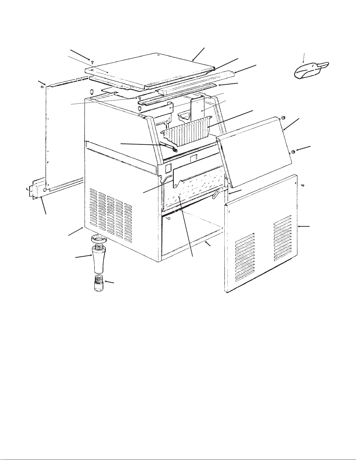
CABINET
12
2a
13
14
15
20
1
2
4
3
19
18
7
21
19
5
6
11
22
Leg Kit:
0650670-00,
9
includes items
9 and 10, but
not spacer
10
ITEM PART
NUMBER NUMBER DESCRIPTION
1. F701939-04 Top panel
2. F784378-00 Insulation
2a F742033-00 Cover
3. F721455-00 Brace
4. F660468-02 Upper Door Frame
5. F660572-01 Door
6. F660286-00 Door Bushing (4)
7. F784169-09R Curtain
8. F721695-01 Front panel,
9. F660257-00 Leg
F660516-00 Leg spacer
10. F660258-01 Leg Leveler
8
16
17
ITEM PART
NUMBER NUMBER DESCRIPTION
12. F702295-00 Back panel
13. F470000-03 Screw
14. F470002-00 Screw
15. F732017-00 Bin Thermo Bracket
16. F791061-02 Unit base assembly
17 F060498-01 Storage Bin Assembly
18 F660470-02 Pump bracket
F660469-02 Curtain bracket
19 02-3253-01 Scoop
20 F721668-05 Front plate
21 F721808-00 Right side panel
22 F721809-00 Left side panel
March 2005
Page 2
Page 3
CSE60 Service Parts
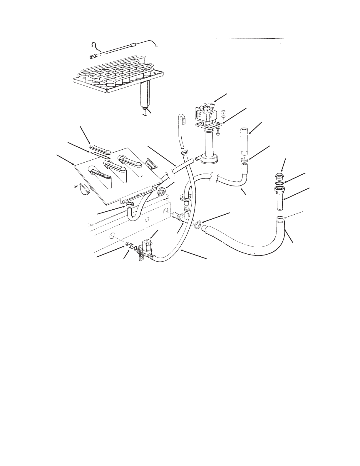
Water System
7
8
1
2
3
4
21
20
6
ITEM PART
NUMBER NUMBER DESCRIPTION
1. F060529-01 Spray nozzle (set of 3)
2. F640041-20 Gasket
3. F793129-04 Spray system (complete)
4. F650499-01 Hose Clamp
5. A32405-001 Inlet Water Valve
6. F610166-00 Hose, Pump To Jets
7. F660463-02 Pump Fan
8. A32588-020 Water Pump
9. F660211-01 Drain Top
10. F660387-01 Stand pipe
11. F640134-00 0-ring
12. F660219-01 Drain Tube Fitting
10
13
9
11
19
12
14
13
5
15
18
16
17
ITEM PART
NUMBER NUMBER DESCRIPTION
13. F460004-00 Hose Clamp
14 F610159-02 Drain tube
15 F660224-00 Drain Fitting
16. F610148-11 Bin Drain Hose
17. F744014-05 Drain Hose Insul.
18. F281900-04 Supply Hose, 1 meter
19. F660535-00 Ring Nut
20. no number part of item 5
21. no number part of item 5
Not Shown,
22. 02165477 Inlet Water
Adaptor (optional)
December 2004
Page 3
Page 4

CSE60 Service Parts
REFRIGERATION
2
1
4
7
6
3
5
8
9
12
10
11
13
14
ITEM PART
NUMBER NUMBER DESCRIPTION
1. F741114-00R Tube Cap
2. F650475-02 Tube
3. F650475-00 Tube Clip
4. F784297-01 Evaporator
5. F620420-00 Condenser
6. F630003-05 Drier
7. F784444-03 Accumulator/suction Line
8. 18-8752-11 Fan Nut
9. A38464-001 Fan Motor
10. F420800-00 Screw
11. 18-8725-21 Fan Blade
12. F704246-03 Fan motor bracket
15
ITEM PART
NUMBER NUMBER DESCRIPTION
13. F620306-27 Hot Gas Valve Body
F620306-51 Hot Gas Valve Coil
14. F630137-00 Strainer
15. F670101-05 Compressor
F620167-55 Start capacitor
F620057-58 Relay
F620058-93 Overload
October 2005
Page 4
Page 5

CSE60 Service Parts
CONTROL BOX
6
7
4
ITEM PART
NUMBER NUMBER DESCRIPTION
1. F620033-01 Toggle Switch
2. F630114-01 Terminal Board
3. F620209-00 Bin Thermostat
4. F470079-00 Screw
F440063-00 Lockwasher
5. F620264-11 Cube Size Control
6 F620443-01 Hi temperature cut out
7 F705219-00 Control box cover
3
5
1
2
December 2004
Page 5
Page 6

CSE60 Service Parts
COMPONENT LAYOUT DIAGRAM
Terminal Board
BK
BU
BK
BU
GR
Bin Temp.
Control
GR
BK
Terminal
Board
HI. Temp. Cut
Out
BK
BK
Cleaning Switch
BK
GR
On-Off
Contact
s
6
BK
3
Cube Size
Contacts
BK
2
4
BK
BK
BK
BU
Pump Motor
GR
BU
Fan Motor
BK
Inlet Water
BK
BU
GR
Valve
Hot Gas Valve
BU
BU
Unit shown in normal ice making
mode.
BK
GR
Compressor
September 2003
Page 6
Page 7

CSE60 Service Parts
SCHEMATIC DIAGRAM
N
Hot Gas Solenoid
Power Supply
Compressor
Cleaning
Switch
L
Bin Temperature
Control
Hi Temp
Control
Solenoid Water Valve
Pump Motor
Fan Motor
6
3
4
On-Off
Contacts
2
Evaporator
Temperature
Control Contacts
June 2001
Page 7
 Loading...