

Page 1

CME506R, CME656R & CME806R Service Parts
This parts list contains the service part numbers for 3 basic
models, plus 4 different electrical configurations. It
contains service parts for all series machines. The series
differences include:
• A - first production
• B - not used
• C - New front panel and side panels
• D - New top panel and PTCR
• E - New side panels and CME506R expansion
valve change
The complete model number will be needed to identify the
correct part.
Unique parts include: cabinet, electrical and refrigeration.
Electrical Codes are located at the end of the model
number (voltage/hertz/phase):
• -1 is 115/60/1
• -32 is 208-230/60/1
• -3 is 208-230/60/3
• -6 is 250/50/1
Electrical Components Common to All Machines
• Inlet water valve
• System controller
• Water sensor
• Discharge line sensor
• Bin controls
• Water level sensor
• Hi pressure cut out
Unique Electrical Components
• Compressor and related starting components
• Contactor (single / three phase)
• Fan motor
• Water pump
• Transformer
• Hot gas valve
Table of Contents
Cabinet .............................................. page 2
Interior Structure and Controls .................................. page 3
CME506 Refrigeration ....................................... page 4
CME506 E Series Refrigeration .................................. page 5
CME656 Refrigeration ....................................... page 6
CME806 Refrigeration ....................................... page 7
Receiver .............................................. page 8
Water System Components .................................... page 9
Compressors and Electrical Components ............................ page 10
HTB555 Ice Storage Bin ..................................... page 11
Remote Condenser ........................................ page 12
Wiring Diagrams .......................................... page 13
December 2003
Page 1
Page 2
CME506R, CME656R & CME806R Service Parts
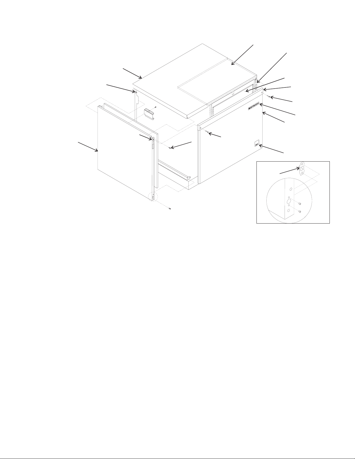
Cabinet
8
5
10
7
Item Part
Number Number Description
1 A37071-021 Right side panel, grey enamel without louvers
A37071-022 A - D series right side panel, stainless steel without louvers
A38126-021 E Series right side panel
2 02-3659-01 Top insulation
3 02-3797-21 C series Front panel kit, gray plastic, includes trim strip & emblems
03-1733-01 Strike (for C model panel, SS and plastic)
A37167-001 Front panel kit, gray plastic, includes item 10a (for A series)
A37488-021 C or higher series Front panel kit, stainless steel, includes trim strip & emblems
A35964-002 Front panel kit, stainless steel (for A models)
3a 15-0808-03 Emblem for ss panel (Scotsman); 03-0271-00 is the speed nut for emblem
3b 15-0792-02 Emblem for C to E series front panel, (CM
4 03-1735-01 Screw for trim strip (for C or D or E series)
03-1404-12 Sheet metal screw for plastic front panel (for A series)
03-1419-22 Sheet metal screw for ss front panel
5 02-1875-03 Panel bumper/hole plug
6 03-1531-01 Sheet metal screw for A - C series
03-1403-19 Machine screw for D series
7 A37070-021 Left side panel, grey enamel without louvers A - D series only
A37070-022 Left side panel, stainless steel without louvers A - D series only
A38127-021 E Series Left side panel
8 A35965-001 Top panel, grey enamel, order item 2 also
A35965-002 Top panel, stainless steel, order item 2 also
02-3822-21 Top panel, plastic, original with D series, fits all and includes item 2
9a 02-3663-01 Evaporator cover, use began Feb. 1997. For A and B series
02-3796-01 Evap cover insulation for above cover
02-3663-20 Evaporator cover w/ins for C - higher series
10 03-1423-06 Speed nut for panel screws
11 03-1733-02 Catch
December 2003
Page 2
6
3
)
12 02-3794-01 Trim strip.
4
03-1731-02 Push nut for trim strip
2
1
9
12
4
3a
3
3b
11
Page 3
CME506R, CME656R & CME806R Service Parts
26
9
20
21
18
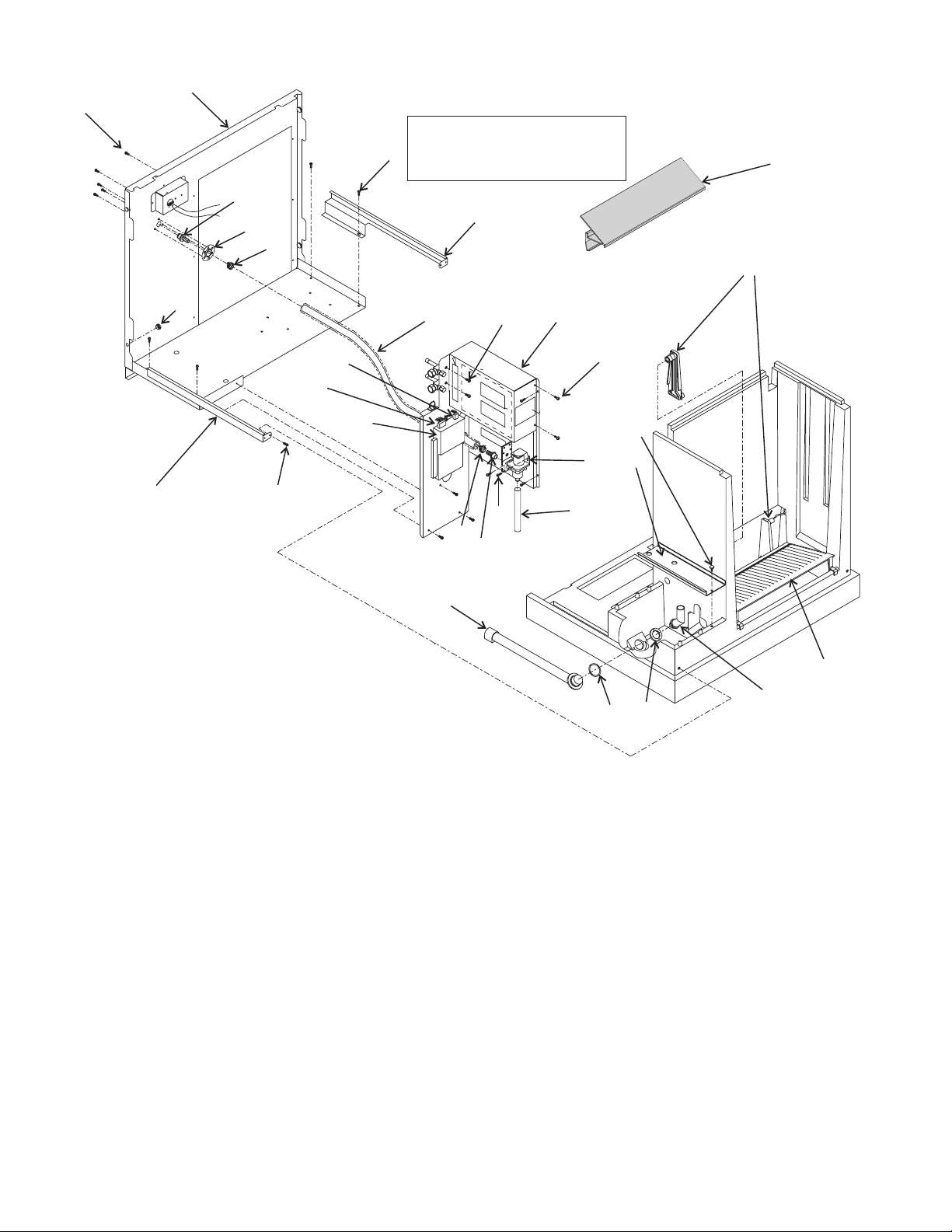
Interior Structure & Controls
Note: Item 25 mounts to Item 1.
Item 1 must have rectangular
7
tabs. All units after 9/96 were
mfg. with rectangular tabs.
10
25
1
19
23
24
22
8
Item Part
Number Number Description
1 11-0540-21 Bin Control Sensor (set)
2 02-3337-01 Cube deflector
3 02-3339-01 Stand pipe
02-3610-01 Stand pipe adjusting nut
4 02-3360-01 Reservoir washer
5 13-0617-56 O-ring
6 02-3338-01 Drain tube & fittings
7 03-1404-18 Screw
8 A36298-001 Left side channel
9 03-1404-07 Screw
10 A36297-001 Right side channel
11 13-0906-01 Plastic Inlet water tube, 21"
not used after Sept. 1996
12 03-1645-01 Screw
13 03-1691-01 Nylon screw
14 02-3340-01 Reservoir cover
15 12-2548-01 Inlet water valve
16 13-0674-02 Tubing, 9" req., order 1 unit
17 obsolete Water inlet fitting for hose
16-1020-01 Water fitting for copper
18 obsolete Clamp for hose
19 13-0903-01 Bumper for side panels
20 16-0997-01 Inlet water fitting for hose
16-1019-01 Inlet water fitting for copper
7
11
6
Item Part
Number Number Description
12
9
18
17
21 16-0701-07 Mounting flange
22 12-2838-23 System controller, fits all
23 12-2541-21 Hi Voltage harness A - C
24 12-2644-02 Lo voltage harness A - C
25 02-3657-01 Cascading shield, use began
26 A36460-001 Back panel assy
27 A35959-001 Hi voltage box cover
27
7
13
14
15
16
4
5
12-2785-01 Hi voltage harness - D series
12-2782-02 Lo voltage harness, D + series
2/97.
2
3
December 2003
Page 3
Page 4
CME506R, CME656R & CME806R Service Parts
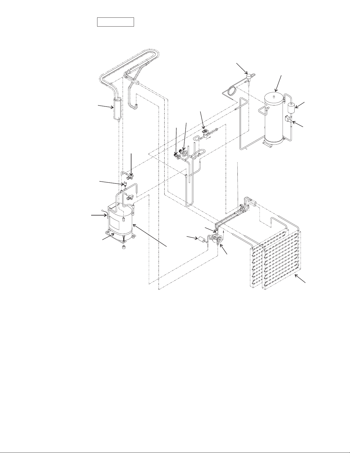
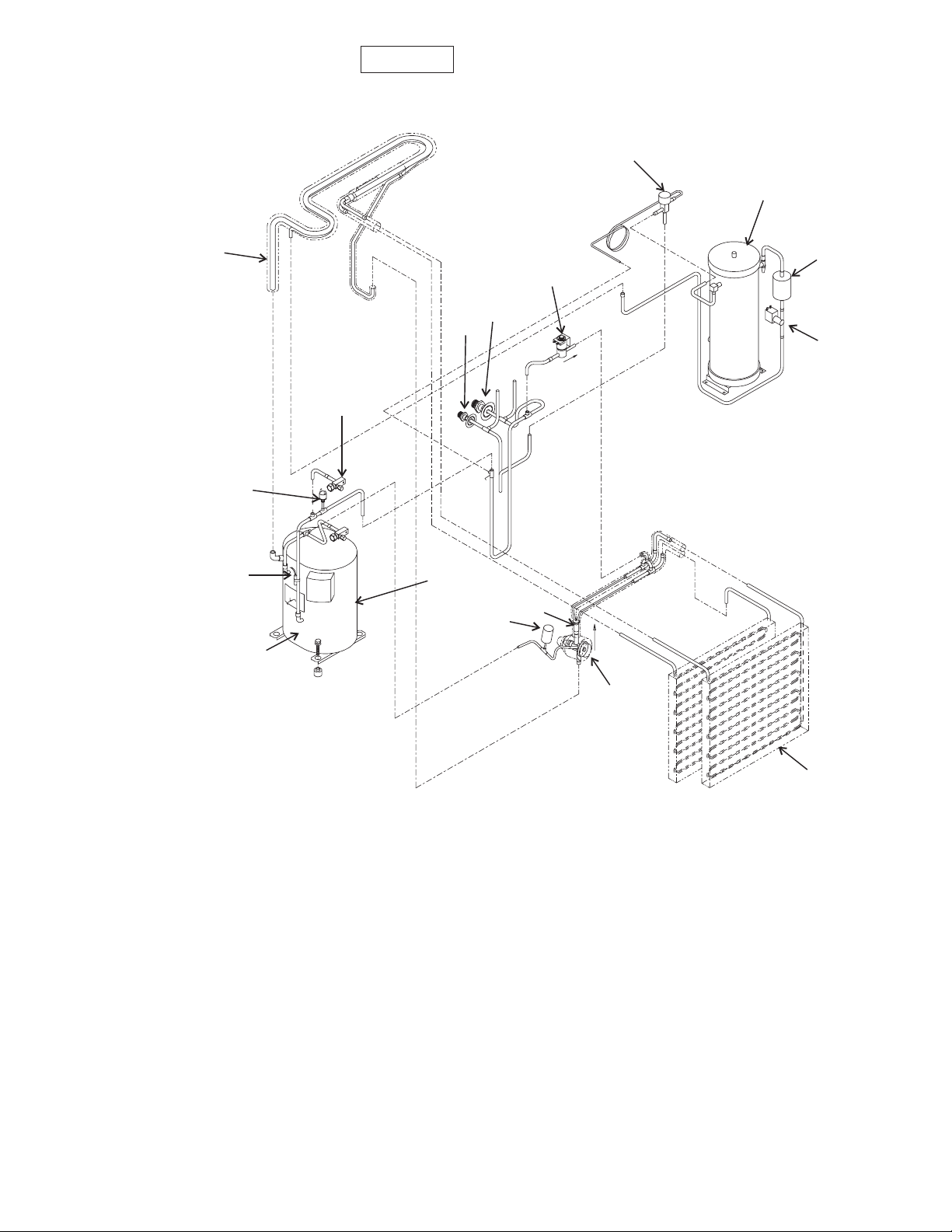
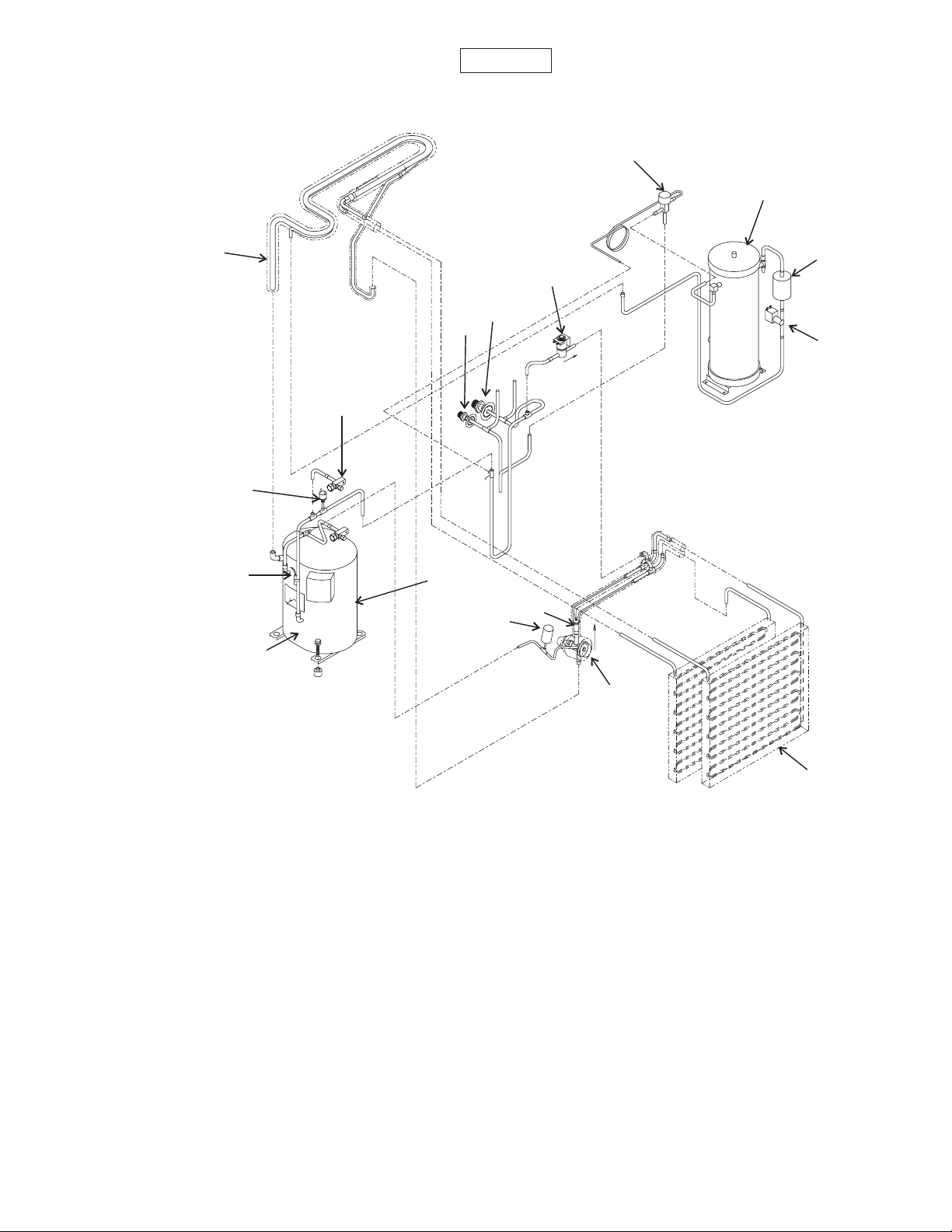
CME506R A - D Series Refrigeration System
16
1
11
14
13
12
10
9
8
Item Part
Number Number Description
1 16-0761-01 Receiver
2 02-3319-02 Dryer
3 12-2471-23 Liquid line valve
4 A36734-020 Evaporator
5 16-1017-21 TXV
02-2920-01 Insulation for TXV
6 11-0502-21 Pump down pressure switch
7 16-0843-03 Distributor and tubes
8 12-1868-01 Crankcase heater
9 02-3410-21 Discharge line temperature sensor, includes
water temp sensor & clip
03-1711-01 Sensor clip
10 11-0501-22 Hi pressure cut out switch
11 16-0778-21 Accumulator
12 16-0832-20 Access valve
16-0832-03 Port cap
16-0832-02 Stem cap
13 16-0850-03 Liquid line fitting
14 16-0850-01 Discharge line fitting
15 12-2471-22 Hot gas valve complete
12-2719-23 Hot gas valve coil
December 2003
6
See Page 10
16 11-0422-24 Discharge pressure control valve
17 16-1063-01 Hot gas valve strainer, not shown
Page 4
2
15
3
7
5
4
Page 5
CME506R, CME656R & CME806R Service Parts
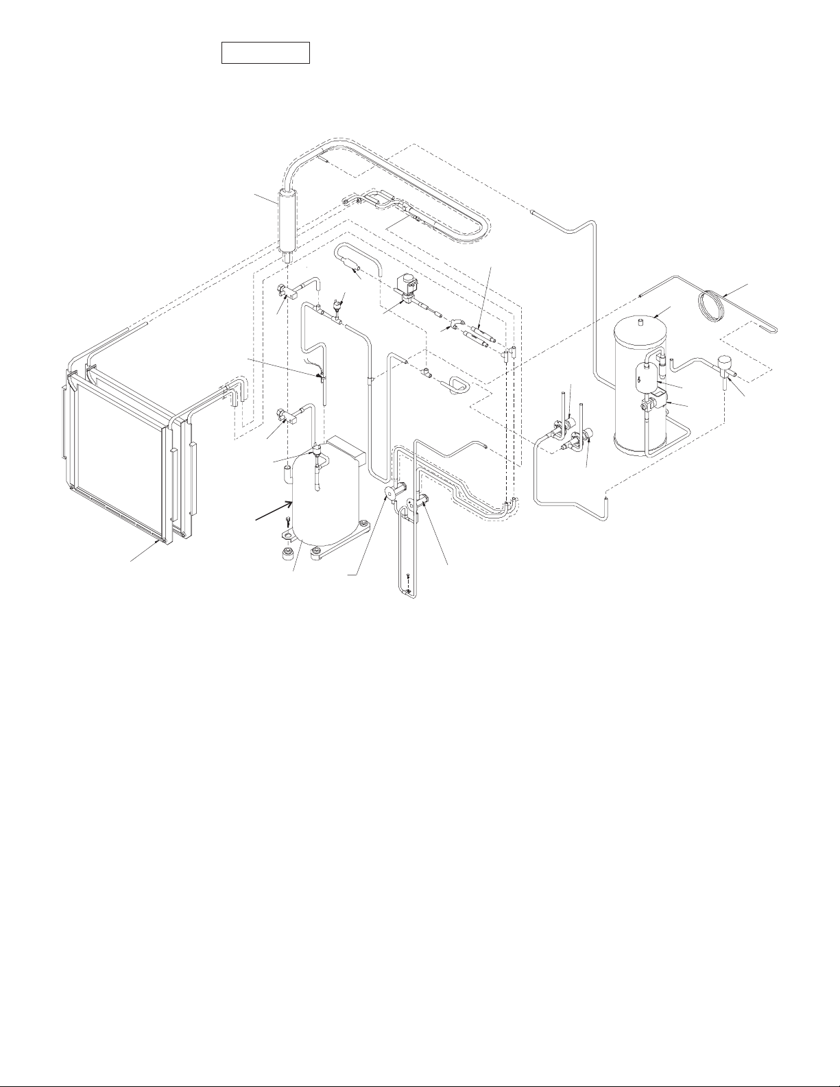
CME506R E & Higher Series Refrigeration System
11
18
10
17
12
9
12
6
15
7
13
14
19
1
2
3
16
See
Page 10
4
8
Item Part
Number Number Description
1 16-0761-01 Receiver
2 02-3319-02 Dryer
3 12-2471-23 Liquid line valve
4 A36734-020 Evaporator
5 16-1009-22 TXV - only for E series
02-3792-01 Insulation for TXV
6 11-0502-21 Pump down pressure switch
7 16-0776-01 Tee
8 12-1868-01 Crankcase heater
9 02-3410-21 Discharge line temperature sensor, includes
water temp sensor & clip
03-1711-01 Sensor clip
10 11-0501-22 Hi pressure cut out switch
11 16-0778-21 Accumulator
12 16-0832-20 Access valve
16-0832-03 Port cap
16-0832-02 Stem cap
13 16-0850-03 Liquid line fitting
14 16-0850-01 Discharge line fitting
15 12-2471-22 Hot gas valve complete
12-2719-23 Hot gas valve coil
5
Item Part
Number Number Description
16 11-0422-24 Discharge pressure control valve
17 16-1063-01 Hot gas valve strainer
18 16-1071-01 Check valve
19 A36427-001 By-pass tubing
December 2003
Page 5
5
Page 6
CME506R, CME656R & CME806R Service Parts
CME656R Refrigeraiton System
16
1
11
14
13
12
10
9
Item Part
Number Number Description
1 16-0761-01 Receiver
2 02-3319-02 Dryer
3 12-2471-23 Liquid line valve
4 A36734-020 Evaporator
5 16-1018-21 TXV
02-2920-01 Insulation for TXV
6 11-0502-21 Pump down pressure switch
7 16-0843-02 Distributor and tubes
8 12-2308-01 Crankcase heater
9 02-3410-21 Discharge line temperature sensor, includes
water temp sensor & clip
03-1711-01 Sensor clip
10 11-0501-22 Hi pressure cut out switch
11 no number Suction line
12 16-0832-20 Access valve
16-0832-03 Port cap
16-0832-02 Stem cap
13 16-0850-03 Liquid line fitting
14 16-0850-01 Discharge line fitting
15 12-2471-22 Hot gas valve complete
12-2719-23 Hot gas valve coil
8
See Page 10
6
16 11-0422-24 Discharge pressure control valve
17 16-1063-01 Hot gas valve strainer,
2
15
3
7
5
4
not shown
December 2003
Page 6
Page 7
CME506R, CME656R & CME806R Service Parts
CME806R Refrigeraiton System
16
1
11
15
14
13
12
10
9
Item Part
Number Number Description
1 16-0761-01 Receiver
2 02-3319-02 Dryer
3 12-2471-23 Liquid line valve
4 A36734-020 Evaporator
5 16-1065-21 TXV
02-3396-01 Insulation for TXV
6 11-0502-21 Pump down pressure switch
7 16-0843-02 Distributor and tubes
8 12-2308-01 Crankcase heater
9 02-3410-21 Discharge line temperature sensor, includes water temp sensor & clip
03-1711-01 Sensor clip
10 11-0501-22 Hi pressure cut out switch
11 no number Suction line
12 16-0832-20 Access valve
16-0832-03 Port cap
16-0832-02 Stem cap
13 16-0850-03 Liquid line fitting
14 16-0850-01 Discharge line fitting
15 12-2471-24 Hot gas valve complete
12-2719-23 Hot gas valve coil
16 11-0422-23 Discharge pressure control valve
8
See Page 10
7
6
5
2
3
4
December 2003
Page 7
Page 8

CME506R, CME656R & CME806R Service Parts
Receiver
1
2
3
4
5
8
Item Part
Number Number Description
1 03-1406-13 Nut
2 03-1410-06 Washer
3 A36454-001 Bracket
4 03-1638-03 Screw
5 03-1531-01 Screw
6 A36440-001 Back cover
7 A36021-001 Bracket
8 03-1645-01 Screw
2
7
1
6
December 2003
Page 8
Page 9

CME506R, CME656R & CME806R Service Parts
Water System Components
3
7
4
5
6
1
1
7
9
2
12
10
11
Item Part
Number Number Description
1 02-2527-01 Water distributor
2 12-2586-27 CME506-1 pump (115/60 Hz)
12-2586-23 CME656 or CME506-6 or CME806 (203-230/50-60 Hz) pump
3 13-0898-01 Tubing grommet
4 02-3336-01 Water distributor tube
5 02-3410-21 Water temperature sensor
includes disch. temp. sensor
6 no number Cable tie
7 02-3405-01 Inlet Tee
13-0840-01 Rubber plug
8 02-3341-01 Float
9 02-3383-02 Float stem grey, non adjustable after 2/97
10 11-0539-21 Float sensor
11 02-3388-04 Front pump bracket for 12-2586 type pump
12 02-3388-05 Rear pump bracket for 12-2586 type pump
13 12-2506-01 Harness
8
October 2005
Page 9
Page 10

CME506R, CME656R & CME806R Service Parts
Compressors and Electrical Components
Bolt
Washer
Grommet, Sleeve
Compressor
Transformer
Relay, A - C
Series
Start Capacitor,
A - C Series
PTCR, D
Series Only
Run Capacitor
Contactor
Model
Voltage/Hz 115/60 250/50 208-230/60 208-230/60 250/50 208-230/60 230/50
Phase Single Single Single Three Single Single Single
Compressor*
PTCR** D
series
Start Relay** 18-1903-50 18-1903-29 18-1903-33 not used 18-1903-29 18-1903-46 18-1903-33
Start
Capacitor**
Run
Capacitor
Overload 18-8711-50 18-8721-50 internal internal internal internal internal
Mounting
Bolt
Sleeve 18-2200-27 18-2200-27 18-2200-27 18-2200-27 18-2200-27 18-2200-27 18-2200-27
Washer 03-1407-07 03-1407-07 03-1407-07 03-1407-07 03-1407-07 03-1407-07 03-1407-07
Grommet 18-2200-28 18-2200-28 18-2200-28 18-2200-28 18-2200-28 18-2200-28 18-2200-28
Contactor 12-2469-01 12-2469-01 12-2469-01 12-2533-01 12-2469-01 12-2469-01 12-2469-01
18-8721-21* 18-8721-22 18-8813-23* 18-8813-25 18-8813-27 18-8749-22* 18-8749-27
18-8835-01 18-8835-01 18-8835-01 18-8835-01 18-8835-01 18-8835-01 18-8835-01
18-1901-03 18-1901-43 18-1901-15 not used 18-1901-52 18-1901-48 18-1901-48
18-1902-45 18-1902-30 18-1902-53 not used 18-1902-53 18-1902-55 18-1902-55
03-1405-20 03-1405-20 03-1405-20 03-1405-20 03-1405-20 03-1405-20 03-1405-20
CME506 CME656 CME806
Transformer A37231-001 A37217-001 A37217-001 A37217-001 A37217-001 A37217-001 A37217-001
December 2003
Page 10
Page 11

CME506R, CME656R & CME806R Service Parts
HTB555 Ice Storage Bin
10
2
8
7
9
Door
Frame
(ref)
11
4
6
1
3
5
Item Part
Number Number Description
1 02-2380-02 Spacer
2 02-3196-01 Hinge
3 02-2806-01 Shoulder screw
4 03-1539-09 E-Ring
5 19-0503-04 Gasket, order 9 units
6 02-3274-02 Door frame - Grey
7 13-0909-01 Door gasket, order 5 units
8 A36481-022 Door - Grey
9 03-0727-11 Thumb screw
10 A35637-001 Canopy
11 A37310001 Baffle
12 02-2809-02 Drain top
13 13-0617-09 O-Ring
14 02-3108-01 Drain bottom
Not shown
05-0586-01 Drain elbow
02-0540-00 Scoop
Bin
Liner
(ref)
14
12
13
Drain Fitting Detail
December 2003
Page 11
Page 12

CME506R, CME656R & CME806R Service Parts
1
2
3
ITEM PART
NUMBER NUMBER DESCRIPTION
1 02-3575-01 Fan guard
2 18-8800-01 Fan blade
3 18-8796-01 Fan motor ERC101
18-8796-32 Fan motor ERC201, ERC402
4 16-0850-01 Quick connect, discharge
5 16-0850-03 Quick connect, liquid
6 A36990-001 Leg kit for ERC101, 201
A36990-002 Leg kit for ERC402
Filters:
02-3231-03 Discharge line
02-3231-02 Liquid line
4
5
6
March 2002
Page 12
Page 13

S)
CME506R, CME656R & CME806R Service Parts
D Series, Single Phase Schematic Diagram
N(115/60/1UNIT
L2 ( 230/50-60/1UNITS)
L1
CRANKCASE HEATER
LI NE
TRANSFORMER
24V
ELECTRONIC CONTROL
HOTGASVALVE
WATER VALVE
HIGH
PRE SSURE
CONTROL
LIQUID LINE
SOL E NO I D
LOW
PRE SSURE
CONTROL
CONTACTORCOI L
SUMP
TEMP.
DI SCHARGE
TEMP.
CONT A CT OR
BIN
FULL
X- MIT
COMPRE S SOR
BIN
FULL
RCV.
WATER
LEVEL
SENSOR
WATER
PUMP
PTCR
RUN
CAP.
REMOTECONDENSER FAN
March 2002
Page 13
Page 14

.
CME506R, CME656R & CME806R Service Parts
D Series, CME506R Wiring Diagram
17-2748-01
BIN FULL
TRANSMITTER
BIN FULL
RECIEVER
WATER
SOLENOID SOLENOID
BU
SUMP TE MP.
SENSOR
DI SCHARGE
TEMP.
SENSOR
WATER
LEVEL
SENSOR
THIS UNIT MUST
BE GROUNDED.
MOT
PUMP
O
O
BK
1 234567 1234
7
6
5
1 2345
ELECTRONIC
4
1 23
CONTROL
3
1 23
2
1 2345
COMMUNICATIONS
1
3 21
PORT
Y
HI PRESSURE
CONTROL
USE COPPER CONDUCTORS ONLY
1 DASHED LINES INDICATE FIELD WIRING WHICH MUST BE
L.L.
SOLENOID
BN
BU
98
Y
O
BK
V
V
LO PRESSURE
CONTROL
HOT GAS
R
W
LI NE
LOAD
TRANSFORMER
Y
EARTH GROUND
POWER SUPPLY
SEE NAMEPLATE FOR
PROPER VOLTAGEREQUIREMENTS
AND MAXIMUM FUSE SIZE
BK/W
JUNCTION
BOX
GROUND
SCREW
O
W
BU BU
32
INSTALLED IN ACCORDANCE WITH THE NATIONAL ELECTRICAL
CODE AND ALL STATE AND LOCAL CODES.
2 WIRE COLOR FOR 115/60/1 UNITS: BLACK
WIRE COLOR FOR 230/50/1 UNITS: BLUE
3 WIRE COLOR FOR 115/60/1 UNITS: WHITE
WIRE COLOR FOR 230/50/1 UNITS: BROWN
CAUTION: PTCR WILL BE HOT.
COMPRESSOR MAY NOT START IF
PTCR IS NOT ALLOWED TO COOL.
Y/W
L1 T1
L2 T2
CONTACTOR
BK
CRANKCASE HEATER
FUSI TE
R
RUNWINDING
BK
S
STARTWINDING
W
CAUTION:
MORETHAN ONEDISCONNECTMEANS MAY BE
1
REMOTE
CONDENSER
FAN
BK
REQUIRED TO D I SCONNECT AL L POWER T O T HIS UNIT
W/ R
C
R
PTCR
RUN
CAP
BK
R/ W
R/ W
YRBK
EXTERNAL
PROTECTOR
COMPRESSOR
March 2002
Page 14
Page 15

.
CME506R, CME656R & CME806R Service Parts
D Series, CME656R and CME806R Single Phase Wiring Diagram
17-2751-01
BIN FULL
TRANSMITTER
BIN FULL
RECIEVER
LB
DI SCHARGE
TEMP.
SENSOR
WATER
LEVEL
SENSOR
THIS UNIT MUST
BE GROUNDED.
USE COPPER CONDUCTORS ONLY
BU
O
ELECTRONI C
CO NTR OL
(AC ONLY)
BN
MOT
FAN
43217654321
W
BK
BK
Y
GRAY
V
HI PRESSURE
CONTROL
(WC ONLY)
SOLENOIDSOLENOID
W
LOAD
TRANSFORMER
CAUTION:
MOR E T H AN O NE D I S CONN EC T ME AN S MA Y B E
REQUI RED TO DI S CONNECT AL L POWER TO T HI S UNI T .
WATER HOT GAS
O
SUMP TE MP.
SENSOR
MOT
PUMP
89
7
6
54321
5
321
4
321
3
54321
2
123
COMMUNICATIONS
1
PORT
O
O
BK
W
LI NE
BK
BK/W
JUNCTION
BOX
POWER SUPPLY
SEE NAMEPLATE FOR
P ROP ER VOL TAGE REQU I RE MENTS
A ND MAX I MUM F USE SI Z E
1 DASHED LINES INDICATE FIELD WIRING WHICH MUST BE
INSTALLED IN ACCORDANCE WITH THE NATIONAL ELECTRICAL
CODE AND ALL STATE AND LOCAL CODES.
C AUT I ON : P TCR WI LL BE HOT .
C O MP RE S S OR MA Y N OT S T A RT I F
P T CR I S NO T A LL O WED T O COOL
W/ Y
T1L1
T2L2
GROUND
SCREW
CONTACTOR
EARTH GROUND
PROTECTOR
INTERNAL
Y
TERMINAL BOX
R
BK
W
COMPRESSOR
W/ R
BK RY
PTCR
RUN
CAP
C1 S2
R3
W/ R
March 2002
Page 15
Page 16

CME506R, CME656R & CME806R Service Parts
D Series, Three Phase Schematic Diagram
L1
CRANKCASE HEATER
LINE
TRANSFORMER
24V
HOT G AS VA LVE
HIG H
PRESSURE
CONTROL
ELECTRONIC CONTROL
WATER VALVE
CONTACTOR CO I L
LOW
PRESS URE
CONTROL
LIQUID LINE
SOLENOID
L2
L3
DI SCH ARGE
TEMP.
CONTACTOR
SUMP
TEMP.
BI N
FULL
X- MI T
BI N
FULL
RCV.
WAT ER
LEVEL
SENSOR
WAT ER
PUMP
CONTACTOR
CONTACTOR
COMPRES SOR
REMOTECONDENSER FAN
March 2002
Page 16
Page 17

.
CME506R, CME656R & CME806R Service Parts
D Series, Three Phase Wiring Diagram
17-2758-01
DI SCHARGE
TEMP.
SENSOR
BIN FULL
TRANSMITTER
BIN FULL
RECIEVER
THIS UNIT MUST
BE GROUNDED.
L.L.
MOT
WATER
SOLENOID SOLENOID
LB
WATER
LEVEL
SENSOR
SUMP TE MP.
SENSOR
O
PUMP
BU
O
O
BK
1 234567 1234
7
6
5
1 2345
ELECTRONIC
4
1 23
CONTROL
3
1 23
2
1 2345
COMMUNICATIONS
1
3 21
PORT
Y
HI PRESSURE
CONTROL
SOLENOID
BN
BK
98
Y
LO PRESSURE
CONTROL
USE COPPER CONDUCTORS ONLY
O
GRAY
O
V
V
TRANSFORMER
Y
EARTH GROUND
SEE NAMEPLATE FOR
PROPER VOLTAGE REQUIREMENTS
AND MAXIMUM FUSE SIZE
HOT GAS
W
LOAD
POWER SUPPLY
BK
LI NE
JUNCTION
BOX
GROUND
SCREW
O
W
BK BK BK
1 DASHED LINES INDICATE FIELD WIRING WHICH MUST BE
INSTALLED IN ACCORDANCE WITH THE NATIONAL ELECTRICAL
CODE AND ALL STATE AND LOCAL CODES.
L1 T1
L2 T2
L3 T3
CONTACTOR
BK
CRANKCASE HEATER
TERMINAL
BOX
R
BK
W
BU BU
1
REMOTE
CONDENSER
FAN
BK
PROTECTOR
INTERNAL
COMPRESSOR
CAUTION:
MORE T HA N ONE DI S CONNE CT MEANS MAY BE
REQUI RED T O D I S CO NNEC T AL L PO WER T O T HI S UNI T
RRR
S2
C1
R3
March 2002
Page 17
Page 18

CME506R, CME656R & CME806R Service Parts
Single Phase Schematic Diagram, A - C Series
March 2002
Page 18
Page 19

CME506R, CME656R & CME806R Service Parts
A -C Series Single Phase Wiring Diagram
March 2002
Page 19
Page 20

CME506R, CME656R & CME806R Service Parts
A -C Series Three Phase Schematic Diagram
March 2002
Page 20
Page 21

CME506R, CME656R & CME806R Service Parts
A - C Series Three Phase Wiring Diagram
March 2002
Page 21
 Loading...