

Scotsman DCE33 Series,DCE33A-1WB,DCE33PA-1WB,DCE33A-1BB,DCE33PA-1BB,DCE33A-1SB,DCE33PA-1SB User Manual
INTRODUCTION
DCE33
The Scotsman DCE33 is a restaurant type ice
machine designed for home use. It produces the
same high quality ice as large Scotsman
commercial ice cube machines, and stores that ice
in a heavily insulated storage bin.
This service manual is intended as a resource for
people installing, using, and servicing the DCE33.
Because it contains information on safety and
maintenance, Scotsman strongly recommends that
this manual be kept where it is readily available.
Table of Contents
Page
Technical Information ............................. 2
Installation:
Water ................................... 3
Plumbing .................................. 4
Add On Kits:
Drain Pump ................................. 9
Door Kit .................................. 10
Reverse Door Swing ............................. 11
Initial Start Up ................................ 12
Operation .................................. 13
Component Location ............................. 14
Maintenance & Cleaning ............................ 15
Winterizing ................................. 15
Cleaning Ice Making System .......................... 16
Adjust Cube Size ............................... 17
Adjust Bin Ice Level .............................. 18
Adjust Timer ................................. 18
Service Diagnosis .............................. 19
Repair:
Curtain ................................... 21
Inlet Water Valve ............................... 21
Timer ................................... 22
Cube Size Control .............................. 23
Bin Thermostat ................................ 23
Water Pump ................................. 24
Parts lists and wiring diagrams are located in the center of the manual, printed on yellow paper.
This manual was printed on
August 1995 recycled paper.
Page 1
DCE33
TECHNICAL INFORMATION
Scotsman Ice Systems are designed and
manufactured with the highest regard for safety
and performance. They meet or exceed the
standards of U.L., and C.U.L.
Scotsman assumes no liability or responsibility of
any kind for products manufactured by Scotsman
that have been altered in any way, including the
use of any parts and/or other components not
specifically approved by Scotsman.
C, el Air In
Serial Number
Tag Location
Warm Air Out
Scotsman reserves the right to make design
changes and/or improvements at any time.
Specifications and designs are subject to change
without notice.
Y
MOOeLHuMeea
seRIALmJ}Aeen Higher BIn
_ Ice Le'_l
TO_L _OAD_PS
_R_ R13_
_ Operating Ilange
VE_e_ 14tLt.&_laINO_, _1,_._ ?_L LR46Se7
SlS_AL tIUMeEn HAZARDOUS MOVING PARTS
J
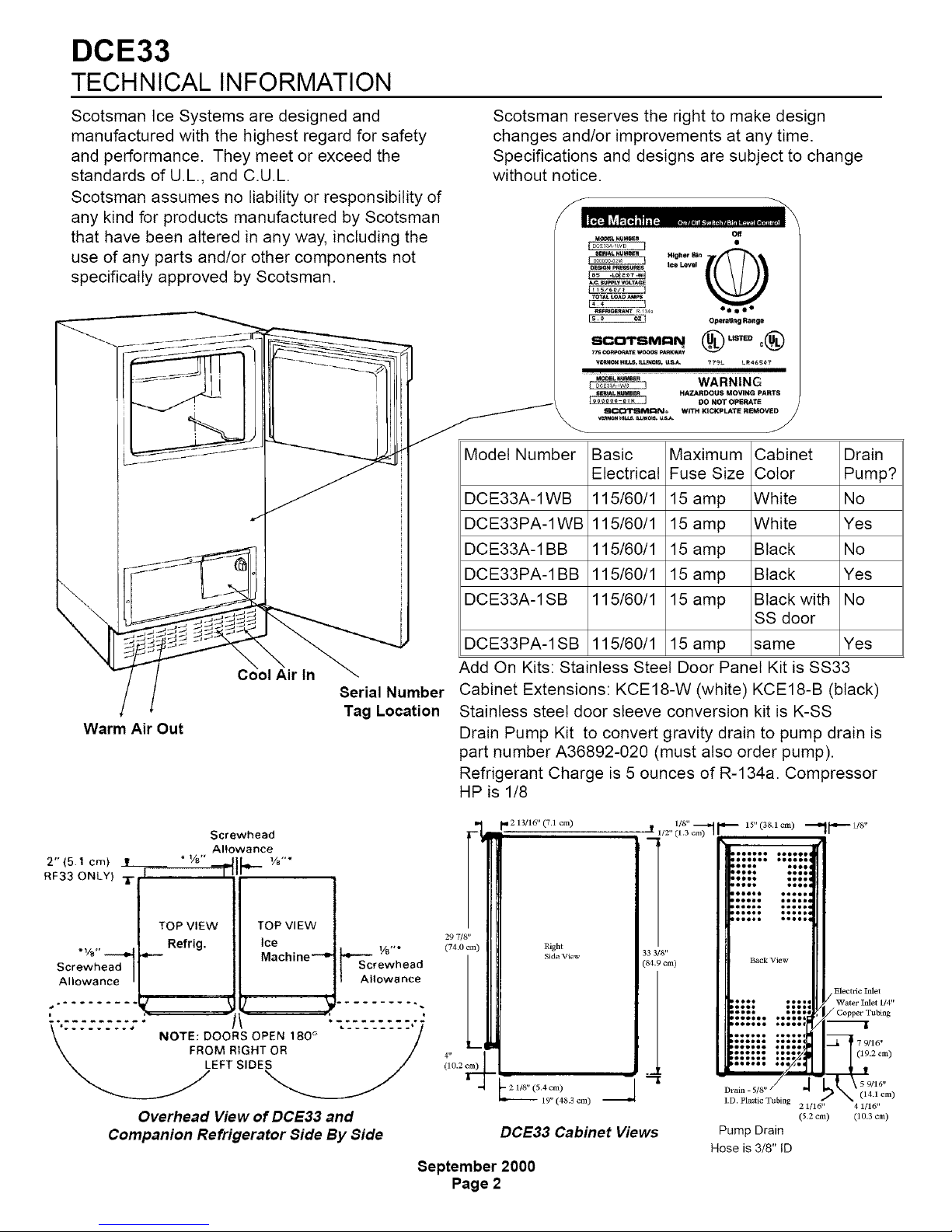
Model Number
DCE33A-1WB
DCE33PA-1WB
DCE33A-1 BB
DCE33PA-1 BB
DCE33A-1 SB
DCE33PA-1 SB
SlI_I_IVN;;N_® WITH KICKPLATE RI_MOVED
Basic
Electrical
115/60/1
115/60/1
115/60/1
115/60/1
115/60/1
115/60/1
Maximum
Fuse Size
15 amp
15 amp
15 amp
15 amp
15 amp
15 amp
Add On Kits: Stainless Steel Door Panel Kit is SS33
Cabinet Extensions: KCE18-W (white) KCE18-B (black)
Stainless steel door sleeve conversion kit is K-SS
Drain Pump Kit to convert gravity drain to pump drain is
part number A36892-020 (must also order pump).
Refrigerant Charge is 5 ounces of R-134a. Compressor
HP is 1/8
Off
X
®°"°°°®
WARNING
DO NOT OPERATE
Cabinet Drain
Color Pump?
White No
White Yes
Black No
Black Yes
Black with No
SS door
same Yes
Screwhead
Allowance
2"(5.1 cm) _t__
RF33 ONLY)
* Vs" --,,_
Screwhead
Allowance
o
a
i
1/8"
-- q-IF-
TOP VIEW
Re!rig.
TOP VIEW
Ice
Machine --e
........ .OTE:OOO"SOPEN'80°" 7
\ FROM RIGHT OR /
Overhead View of DCE33 and
Companion Refrigerator Side By Side
213/16" (7.1 cm)
8
rewhead
1 Allowance
INSTALLATION
DOE33
To properly make and store ice, the DCE33
requires access to air, potable water, 115 volt
electricity and a drain. The machine must be
installed indoors, in a controlled environment.
Air: The ice machine uses a fan to take in room air
at the front of the machine through the right side of
the kick plate. It discharges warm air out the left
side of the kick plate. Anything placed in front of
the kick plate will restrict air flow and cause a
decrease in performance and efficiency. The
minimum air temperature the machine will operate
in is 500 F., and the maximum is 100 ° F.
Water Supply: The ice machine requires a
continuous supply of potable water at no less than
20 p.s.i.g, of flowing pressure. Static water
pressure should not exceed 80 p.s.i.g. The
minimum water temperature the machine will
operate in is 400 F., and the maximum is 100 ° F.
Water Quality:
There is no such thing as "pure" water; all water,
including potable water supplied by municipalities,
contains some "impurities". Water absorbs
impurities from the air as rain and/or as it flows
through the ground. Some of the impurities are
solid particles, these are known as suspended
solids, and a fine particle filter witl remove them.
Other impurities are chemically bonded to the
water molecules, and cannot be filtered out, these
are called dissolved solids.
Ice made by the DCE33 will have a lower
mineral content than the water it was made
from.
Purer water witl freeze first in the ice making
molds. The reason for this is that anything
dissolved in water lowers the water's freezing
temperature.
This concentrates most of the impurities in the ice
machine water reservoir where they may form
hard deposits known as scale. The DCE33 dilutes
the concentration of minerals by over-filling the
reservoir during the harvest cycle (with the excess
water flowing down the drain). About 3 quarts of
water flow into the unit each cycle. About 1 quart
of that rinses the reservoir and goes down the
drain.
To keep the machine operating properly, these
impurities or minerals will have to be regularly
dissolved by an acid cleaning, using Scotsman Ice
Machine Cleaner. Directions for this may be found
in the section under cleaning.
In general, it is always a good idea to filter the
water. A water filter, if it is of the proper type, can
remove taste and odors as well as particles. Some
methods of water treatment for dissolved solids
include reverse osmosis, and polyphosphate
feeders. A reverse osmosis system should include
post treatment to satisfy the R.O. water's
"aggressiveness".
Deionized water is not recommended.
Because water softeners exchange one mineral
for another, Scotsman does not recommend their
use for ice machines. Where water is very hard,
softened water may result in white, mushy cubes
that stick together.
Scotsman suggests, that if in doubt about the
water, that a local point of use water specialist be
contacted for recommendations on water
treatment.
Electricity: The machine is supplied with a cord,
and may be plugged into a wall outlet. The ice
machine should be the only device using that
circuit.
The fuse (or circuit breaker) size should be 15
amps.
Drain: There are two DCE33 models:
The DCE33A-1 is a gravity drain model that
requires a drain tube that's pitched down from the
outlet at the back of the cabinet to the connection
to the sanitary sewer.
The DCE33PA-1 has a built in drain pump that will
pump water up to a drain point, such as a nearby
sink.
Some impurities will inevitably remain, and will
stick to the parts in the machine, and will cause
malformed ice cubes. Eventually, built up mineral
scale can shorten machine life.
June 2000
Page 3
DCE33
TO INSTALL: Plumbing
The water supply and drain should be roughed in
and ready at the point of installation. A walt outlet
directly behind the ice machine will make
undercounter installation easier. All electrical,
water and drain connections must conform to local
codes.
Installation Cautions: Although the DCE33 has
been designed to be serviced in place, in some
cases it may be necessary to pull the unit out for
service. For that reason do not restrict access to
the cabinet at the front - top and bottom.
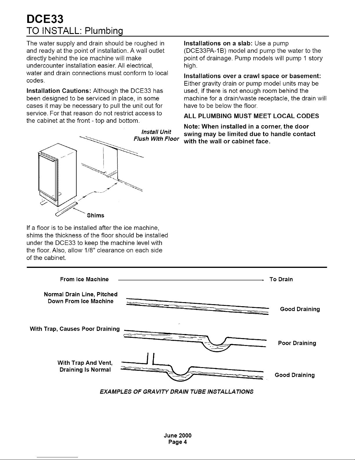
Install Unit
lush With Floor
Installations on a slab: Use a pump
(DCE33PA-1 B) model and pump the water to the
point of drainage. Pump models wilt pump 1 story
high.
Installations over a crawl space or basement:
Either gravity drain or pump model units may be
used, if there is not enough room behind the
machine for a drain/waste receptacle, the drain will
have to be below the floor.
ALL PLUMBING MUST MEET LOCAL CODES
Note: When installed in a corner, the door
swing may be limited due to handle contact
with the wall or cabinet face.
Shims
If a floor is to be installed after the ice machine,
shims the thickness of the floor should be installed
under the DCE33 to keep the machine level with
the floor. Also, allow 1/8" clearance on each side
of the cabinet.
From Ice Machine
Normal Drain Line, Pitched
Down From Ice Machine
With Trap, Causes Poor Draining --
o __ .
With Trap And Vent,
Draining Is Normal
To Drain
Good Draining
Poor Draining
Good Draining
EXAMPLES OF GRAVITY DRAIN TUBE INSTALLATIONS
June 2000
Page 4
TO INSTALL: Plumbing
DCE33
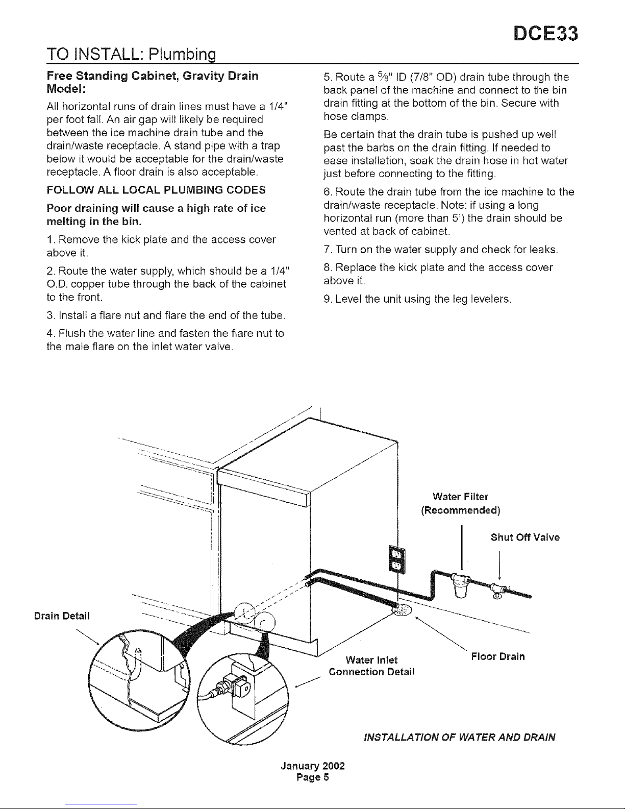
Free Standing Cabinet, Gravity Drain
Model:
All horizontal runs of drain lines must have a 1/4"
per foot fall. An air gap wilt likely be required
between the ice machine drain tube and the
drain/waste receptacle. A stand pipe with a trap
below it would be acceptable for the drain/waste
receptacle. A floor drain is also acceptable.
FOLLOW ALL LOCAL PLUMBING CODES
Poor draining will cause a high rate of ice
melting in the bin.
1. Remove the kick plate and the access cover
above it.
2. Route the water supply, which should be a 1/4"
O.D. copper tube through the back of the cabinet
to the front.
3. Install a flare nut and flare the end of the tube.
4. Flush the water line and fasten the flare nut to
the male flare on the inlet water valve.
5. Route a 5/8" ID (7/8" OD) drain tube through the
back panel of the machine and connect to the bin
drain fitting at the bottom of the bin. Secure with
hose clamps.
Be certain that the drain tube is pushed up well
past the barbs on the drain fitting. If needed to
ease installation, soak the drain hose in hot water
just before connecting to the fitting.
6. Route the drain tube from the ice machine to the
drain/waste receptacle. Note: if using a long
horizontal run (more than 5') the drain should be
vented at back of cabinet.
7. Turn on the water supply and check for leaks.
8. Replace the kick plate and the access cover
above it.
9. Level the unit using the leg levelers.
Connection Detail
January 2002
Page 5
Water Filter
(Recommended)
Shut Off Valve
Water Inlet
INSTALLATION OF WATER AND DRAIN
Floor Drain
DCE33
TO INSTALL: Plumbing
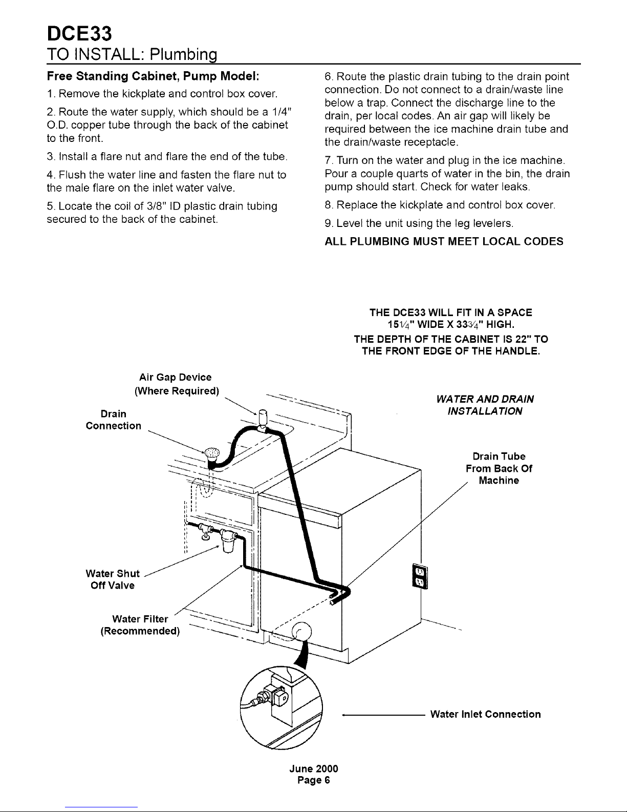
Free Standing Cabinet, Pump Model:
1. Remove the kickptate and control box cover.
2. Route the water supply, which should be a 1/4"
O.D. copper tube through the back of the cabinet
to the front.
3. Install a flare nut and flare the end of the tube.
4. Flush the water line and fasten the flare nut to
the male flare on the inlet water valve.
5. Locate the coil of 3/8" ID plastic drain tubing
secured to the back of the cabinet.
6. Route the plastic drain tubing to the drain point
connection. Do not connect to a drain/waste line
below a trap. Connect the discharge line to the
drain, per local codes. An air gap will likely be
required between the ice machine drain tube and
the drain/waste receptacle.
7. Turn on the water and plug in the ice machine.
Pour a couple quarts of water in the bin, the drain
pump should start. Check for water leaks.
8. Replace the kickptate and control box cover.
9. Level the unit using the leg levelers.
ALL PLUMBING MUST MEET LOCAL CODES
THE DCE33 WILL FIT IN A SPACE
151/4"WIDE X 333/4" HIGH.
THE DEPTH OF THE CABINET IS 22" TO
THE FRONT EDGE OF THE HANDLE.
Drain
Connection
Water Sh ut
Off Valve
Water Filter
(Recommended)
Air Gap Device
(Where Required)
WATER AND DRAIN
INS TALLA TION
Drain Tube
From Back Of
Machine
Water Inlet Connection
June 2000
Page 6

TO INSTALL: Plumbing
Built In, Gravity Drain Model:
The drain and inlet water tubes must be plumbed
before connecting to the ice machine. All horizontal
runs of drain lines must have a 1/4" per foot fall. An
air gap will likely be required between the ice
machine drain tube and the drain/waste
receptacle. A stand pipe with a trap below it would
be acceptable for the drain/waste receptacle.
Note: Poor draining will cause a high rate of ice
melting in the bin,
1. Place ice machine in front of installed location.
Adjust leg levelers to approximately correct
position.
2. Remove kickptate and the access cover above it.
3. Route water inlet line, which should be a 1/4"
O.D. copper tube, from walt through ice machine to
the front.
4. Route drain line from wall position through ice
machine. Note: if using a tong horizontal run (more
than 5') the drain should be vented at back of
cabinet.
DCE33
6. Push ice machine into installed position.
7. Cut off water inlet line at required length.
8. Flush water line. Place flare nut on inlet water
line and flare the end of the copper tube.
9. Attach flare nut to the male flare on the inlet
water valve.
10. Cut off the drain tube to the required length.
11. Route a 5/8"drain tube through the back panel
of the machine and connect to the bin drain fitting
at the bottom of the bin. Secure with hose clamps.
Be certain that the drain tube is pushed up well
past the barbs on the drain fitting. If needed to
ease installation, soak the drain hose in hot water
just before connecting to the fitting.
12. Turn on the water supply and check for leaks.
13. Replace the kickptate and the access cover
above it. Level as needed.
ALL PLUMBING MUST MEET LOCAL CODES
5. If electrical outlet for ice machine is behind the
cabinet, plug in the ice machine now.
INSTALLATION OF WATER
AND DRAIN _
I
Drain
Connection
Water Filter
(Recommended)
Water inlet Connection
Detail
January 2002
Page 7
DCE33
TO INSTALL: Plumbing
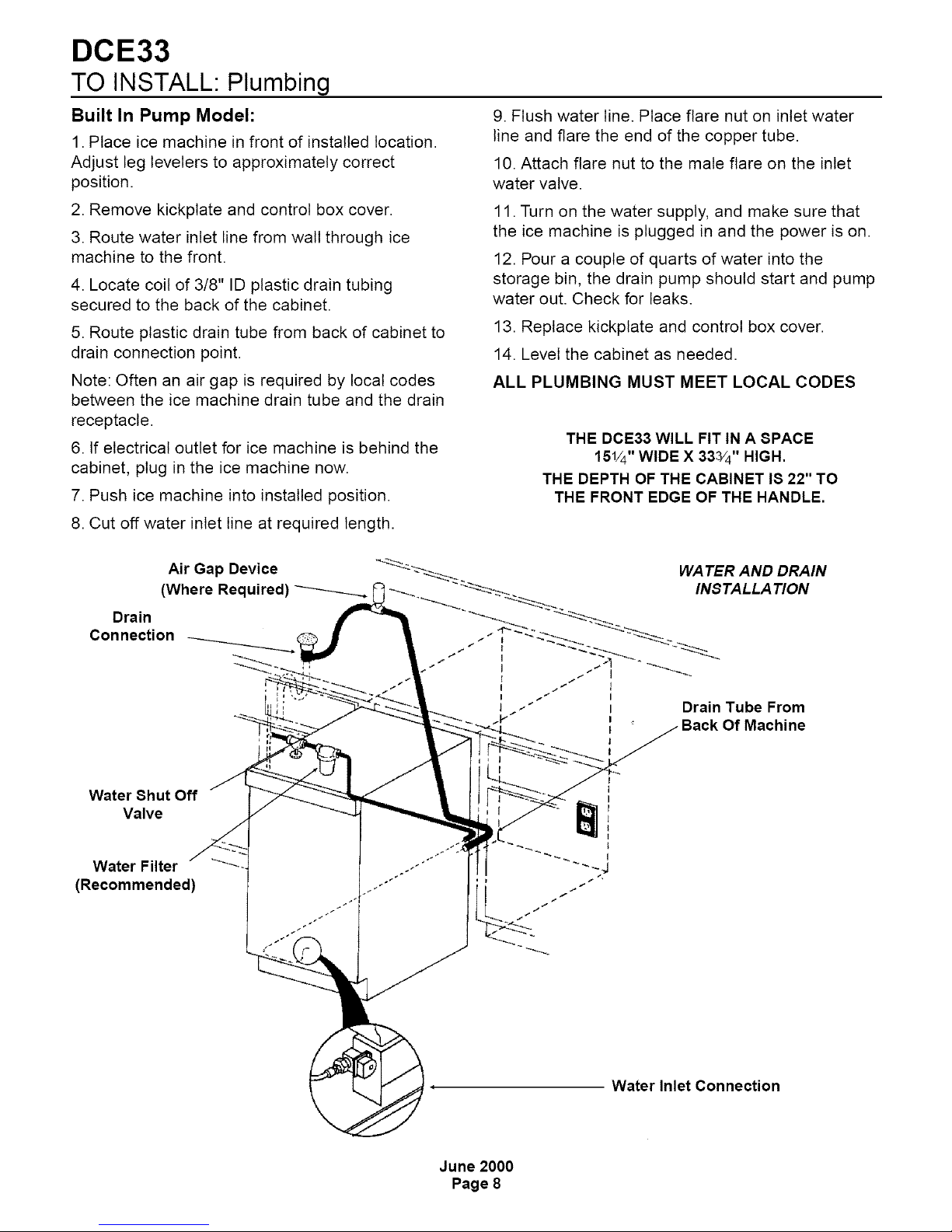
Built In Pump Model:
1. Place ice machine in front of installed location.
Adjust leg levelers to approximately correct
position.
2. Remove kickplate and control box cover.
3. Route water inlet line from walt through ice
machine to the front.
4. Locate coil of 3/8" ID plastic drain tubing
secured to the back of the cabinet.
5. Route plastic drain tube from back of cabinet to
drain connection point.
Note: Often an air gap is required by local codes
between the ice machine drain tube and the drain
receptacle.
6. If electrical outlet for ice machine is behind the
cabinet, plug in the ice machine now.
7. Push ice machine into installed position.
8. Cut off water inlet line at required length.
9. Flush water line. Place flare nut on inlet water
line and flare the end of the copper tube.
10. Attach flare nut to the male flare on the inlet
water valve.
11. Turn on the water supply, and make sure that
the ice machine is plugged in and the power is on.
12. Pour a couple of quarts of water into the
storage bin, the drain pump should start and pump
water out. Check for leaks.
13. Replace kickplate and control box cover.
14. Level the cabinet as needed.
ALL PLUMBING MUST MEET LOCAL CODES
THE DCE33 WILL FIT IN A SPACE
151/4"WIDE X 333/4" HIGH.
THE DEPTH OF THE CABINET 18 22" TO
THE FRONT EDGE OF THE HANDLE.
Air Gap Device
(Where Required)
Drain
Con nection
Water Shut Off
Valve
Water Filter
(Recommended)
WATER AND DRAIN
INS TALLA TION
I /_" l
I / _ I
l i" I Drain Tube From
t . Back Of Machine
I
I
I
I
r
I
t
I
Water Inlet Connection
June 2000
Page 8
 Loading...