

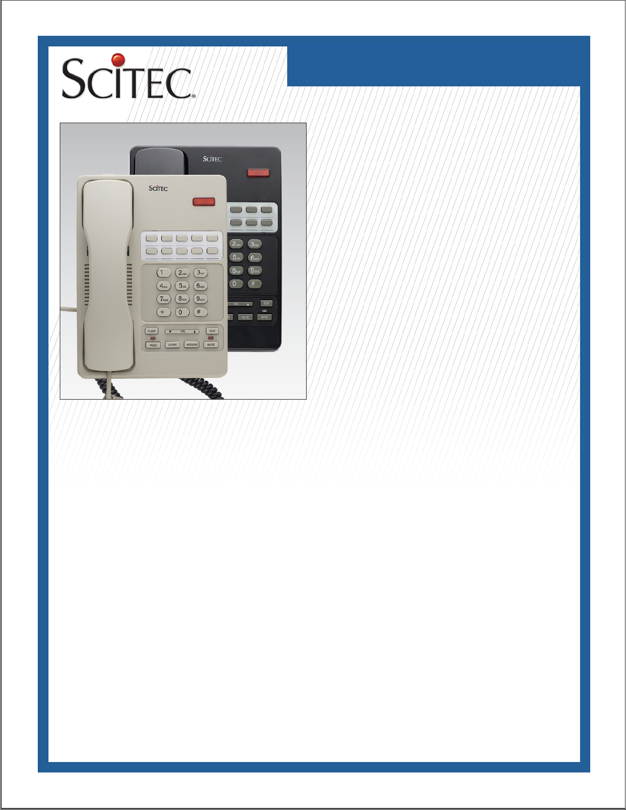
STC-7001 / STC-7002
Telephone User Guide
STC-7001/STC-7002 SingleLine Feature/Speakerphone
This telephone user guide details installation, programming,
and operation instructions for the STC-7001 single-line feature
phone and STC-7002 speakerphone. Please refer to the Scitec
website News section and click on Product Notes for updates to
this and other Scitec products.
Package Contents
• Telephone base unit
• Handset
• Coiled handset cord
• Straight line cord
• Note: Wall mount bracket sold separately
Installation
The telephone is designed for use behind a registered PABX
system. The PABX “station port” type must be “industry standard analog” or “POTS.” This telephone cannot be used with
“digital” PABX station ports. The telephone user or installer must
supply a 2-wire, RJ-11 modular wall jack to connect this telephone to the PABX system.
To install telephone, rst snap supplied coiled handset cord into
the jack on the end of handset. Then place the handset in
its cradle. Connect the free end of the coiled handset cord to
the jack on LEFT SIDE of the telephone body, marked with a
“handset” symbol. This jack is closer to the front of the telephone. Next, take supplied straight modular cord and insert it
into jack on the REAR of telephone. Connect the other end of
this cord to telephone system wall jack. Lift the handset. A dial
tone should be heard.
Assembly
If you will be wall-mounting your phone, it is best to do the conversion before connecting the handset and line cords. If you will
using the phone on a desktop, attach the handset.
Attaching the handset
Connect the supplied coiled handset cord between the jack on
the end of handset and the jack marked with a “handset” symbol
on the left side of the telephone base unit. Place the handset
on the telephone base unit or if wall-mounted, hang it on the
desk/wall-mount clip to depress the hook switch.
Wall-mounting
• The wall/desk handset clip located on the front of the phone
directly above the speaker grill. In its wall-mount position, the
clip extends up to hold the handset in place. Gently pull it up
and turn ½ turn to change from desk to wall mount. This clip is
spring-loaded and not removable, so that it cannot be lost.
• Turn the telephone over so the telephone face is down.
• Connect line cord to the jack on rear of phone. Route the line
cord through the line cord channel. Pass the other end of the
line cord through the rectangular hole in the back of the mounting bracket Coil up any excess line cord length for placement
between the telephone and the wall-mounting bracket.
• Position the wall-mounting bracket so that the Scitec “Sun”
designs are toward the front edge of the phone and the four
retaining tabs on the bracket line up with the slots in the bottom
of the phone. Firmly press on the bracket to snap it into place.
• Connect the free end of the RJ-11 line cord to the wall jack.
Hold telephone in front of the 2 mushroom shaped mounting
posts on the wall jack plate. Line up keyholes on wall-mounting
bracket with posts. After engaging wall-mounting bracket with
posts, slide telephone down slightly. When properly installed,
the telephone will be rmly attached to the wall.

STC-7001 / STC-7002
Telephone User Guide
Features
MESSAGE LIGHT - Dual-function message light is compatible
with high voltage neon and AT&T/Lucent/Avaya LED message
waiting light systems.
SPEED DIAL MEMORY KEYS - 10 user-programmable memory
keys, each with a capacity of 1632 digits. [FLASH] and [PAUSE]
are storable.
HOLD KEY - Each press toggles the “local hold” function alternately on or off. The LED located above this key indicates the
on-hold status.
STORE KEY - Used to program speed-dial memory keys.
MUTE KEY- Sets the microphone mute function on and off. The
red LED in the SPKR/MUTE (7002) indicator displays the on/off
status of the mute function. When mute is on, the handset and
handsfree microphone audio is turned off. You will be able to
hear the party at the other end of your call, but they will not be
able to hear you.
SPKR KEY - (7002): Sets the handsfree speakerphone function
on or off. The green LED in the SPKR/MUTE indicator displays
the on/off status of the speakerphone.
SPKR/MUTE INDICATOR - (7002) A two-color red/green LED
located above the [SPKR] key. This indicator displays the status
of the speakerphone and hold functions. Red indicates that
handset microphone mute is on, green indicates that the speakerphone is on, and red/green indicates that the speakerphone
is on with its microphone muted.
RINGER VOLUME CONTROL SWITCH - Sets the ringer
volume level to HI, LOW, or OFF.
VOLUME CONTROL TOGGLE - Sets the handset and speakerphone volume to one of four levels [Normal - Medium - High Highest].
DATAPORT - Provides a convenient extension of the connected
telephone line for connecting a device such as a modem, fax,
or answering machine.
HEARING AID COMPATIBLE HEADSET - ADA/HAC-compliant
HANDSET HOLDER - Clip located above the handset cradle.
Used in wall mount applications to conveniently hold an “offhook” handset.
FLASH - Pressing the [FLASH] key has the same effect as “tapping” the hookswitch. It is used to access PBX system features,
such as “system hold,” “transfer/conference,” or “call park.” The
standard ash time is 600msec. [FLASH] is storable in the programmable speed-dial memory keys, along with other digits.
Please refer to your PBX system manual for additional information and the exact digit sequences required for accessing special PBX system features.
[RD/P] - Pressing this key immediately after the phone is taken
off-hook redials the last number dialed, up to 32 digits. Pressing
this key after dialing a digit inserts a 3.6 second pause into the
dialing sequence.
Placing a call
Using the handset: Lift the handset
Using the speakerphone (7002): Press the [SPKR] key.
Dial a telephone number by pressing:
• The desired digit keys in sequence
• The [RD/P] key to redial the last number dialed
• A speed-dial memory key to dial a stored number.
Answering a call
Using the handset: Lift the handset
Using the speakerphone (7002): Press the [SPKR] key.
Placing a call on hold
Using the handset: During a call, press the [HOLD] key. Place
the handset in its cradle.
Using speakerphone (7002): Press the [HOLD] key.
Retrieving a held call
Using the handset: Lift the handset.
Using the speakerphone: Press the [SPKR] key.
Adjusting Handset or Speakerphone Volume Level
Press the [?] key to increase the volume or the [?] key to
decrease the volume. The volume may be set to one of four
levels [Low - Medium - High - Highest].

STC-7001 / STC-7002
Telephone User Guide
Setting the Ringer Volume
The ringer volume switch is located on the rear of telephone. It
is a slide switch with three positions - OFF, LOW, and HI. Setting the switch to “OFF” disables audible ringing. The “LOW”
setting is recommended for most users. The “HI” setting is recommended if the telephone is installed in a noisy location.
Speed-Dial Memory Key Programming
1. Plug the telephone into an active telephone line. This is
required to program the speed-dial memory keys.
2. Lift the handset, or press [SPKR] to take telephone “off-hook.”
3. Press the [STORE] key
4. Press the desired sequence of telephone number keys,
[FLASH] key or [RD/P] key as desired (up to a total of 1632
keys.) Note: The [RD/P] key will insert a 3.6 second pause into
the dialed sequence. If a “9” prex (or any other digit) is required
to access an outside telephone line, a “pause” may be required
after the rst number dialed. For example: 9 [RD/P] 1- 800555-1212.
5. Press the destination [MEMORY] key (one of nineten available) to store the keyed sequence into memory.
6. Optional) Press the [MEMORY] key and verify that the programmed sequence is automatically dialed.
7. To program additional speed-dial memory keys, repeat steps
two through six. It is not necessary to hang up or hear dial tone
prior to programming additional keys.
Note - Speed-dial memory key contents are stored in a non-volatile memory. An active telephone line connection is not required
to retain the contents of the speed-dial key memory.
Flash time programming
The procedure is as follows: off-hook+[STORE] key+1 or 3 or
6+[STORE] key+[FLASH] key, here 1,3,6 respectively denotes
100ms,300ms,600ms of ash time.
Pause time programming
The procedure is as follows: off-hook+[STORE] key+1 or 2 or
3 or 4+[STORE] key+[PAUSE] key, here 1,2,3,4 respectively
denotes 1s,2s,3s,4s of pause time.
HOLD May Be Programmed As PBX Hold
The procedure is as follows: off-hook+[STORE] key+ PBX
hold activating passcode+[STORE] key+[HOLD] key.
The procedure to cancel the code setting in Speed-dial
keys, [MSG] key, [FLASH] key, [PAUSE] key and [HOLD] key
is as follows: off-hook+[STORE] key+[STORE] key+ Speed-
dial keys, [MSG] key, [FLASH] key, [PAUSE] key or [HOLD]
key.
Speed-Dial Memory Key Labeling (optional)
1. Obtain a pin, sewing needle, knife blade, or similar pointed tool.
2. Press down on the center speed-dial key. Carefully insert the
tool in between the upper or lower edge of the pressed speeddial key and its hole in the faceplate. Pry up on the center of
the faceplate and lift upward to remove the faceplate from the
telephone. Carefully insert the tool in the right hole in the PVC
faceplate. Pry up on the right side hole of the faceplate and lift
upward to remove the PVC faceplate from the telephone.
3. Remove the transparent key caps from the nine speed-dial
keys. Insert labels of your choice between the keys and the
transparent key covers. Directly write your desired telephone
numbers in the blanks with underscore.
4. Orient the faceplate so that the two pins molded on the back
of the faceplate align with the corresponding holes on the telephone body. Carefully reinstall the faceplate by inserting the
four tabs on the faceplate into the four retaining slots on the
telephone body.Orient the PVC faceplate by inserting the four
tabs on the faceplate into the four retaining slots on the telephone body.
Dataport
The DATA jack, located on the right side of the telephone, provides a convenient extension of the connected telephone line.
This jack may be used to connect a computer modem, credit
card terminal, or other similar accessory device directly to the
telephone line. Note that the telephone and a connected accessory device are sharing the connected telephone line and may
not be used simultaneously. Do not attempt to use the data port
for connecting the handset to the telephone. The data port is
to be used only for connecting computer modems or similar
accessory devices directly to the telephone line.
STC-7001 / STC-7002
Telephone User Guide
Required FCC Notice
This equipment complies with Part 68 of the FCC rules and
the requirements adopted by the ACTA. On the bottom of
this equipment is a label that contains, among other information, a product identier in the format US:AAAEQ##TXXXX. If
requested, this number must be provided to the telephone company. The REN is used to determine the number of devices that
may be connected to a telephone line. Excessive RENs on a
telephone line may result in the devices not ringing in response
to an incoming call. In most but not all areas, the sum of RENs
should not exceed ve (5.0). To be certain of the number of
devices that may be connected to a line, as determined by the
total RENs, contact the local telephone company. The REN
for this telephone is part of the product identier that has the
format US:AAAEQ##TXXXX. The digits represented by ## are
the REN without a decimal point (e.g., 03 is a REN of 0.3).
If this equipment causes harm to the telephone network, the
telephone company will notify you in advance that temporary
discontinuance of service may be required. If advance notice
isn’t practical, the Telephone Company will notify you as soon
as possible. Also, you will be advised of your right to le a complaint with the FCC if you believe it is necessary. The Telephone
Company may make changes in its facilities, equipment, operations, or procedures that could affect the operation of this telephone. If this happens, the Telephone Company will provide
advance notice in order for you to make the necessary modications in order to maintain uninterrupted service. If you experience trouble with this telephone, please contact Scitec, Inc. at
(217) 384-6041 for repair or warranty information. If the trouble
is causing harm to the telephone network, the Telephone Company may request that you
Required FCC Notice
remove this equipment from the network until the problem is
resolved. The customer can do the following repairs: replacement of cords or handset; replacement of window for telephone
number. Connection to party line service is subject to state tariffs. Contact the state public utility commission, public service
commission or corporation commission for information. This
telephone cannot be used on Telephone Company provided
coin service. If your home has specially wired alarm equipment
connected to the telephone line, ensure the installation of the
telephone does not disable your alarm equipment. If you have
questions about what will disable alarm equipment, consult your
telephone company or a qualied installer. This equipment is
hearing aid compatible. If the telephone is used with a leased
system, permission of the owner of the equipment must be
obtained for connection of the telephone because modication
of the host system is often required.
Jacks
A plug and jack used to connect this equipment to the premises
wiring and telephone network must comply with the applicable
FCC Part 68 rules and requirements adopted by the ACTA. A
compliant telephone cord and modular plug is provided with this
product. It is designed to be connected to a compatible modular
jack that is also compliant.
5025 Galley Road
Colorado Springs, CO 81915 USA
+1.719.638.8821 tel
+1.719.638.8815 fax
info@scitecinc.com
www.scitecinc.com
Scitec is a registered trademark of Scitec Inc.
© 2009 Scitec, Inc.
Specications subject to change without notice.
Refer to www.scitecinc.com for latest data.
Scitec, Inc. is a minority-owned business.
 Loading...