

Scitec Aegis-LBE-08,2554E,2510E User Manual
Be prepared.
2510E
2554E
Emergency Series
User Guide
Aegis-LBE-08, 2554E, 2510E
Aegis-LBE-08
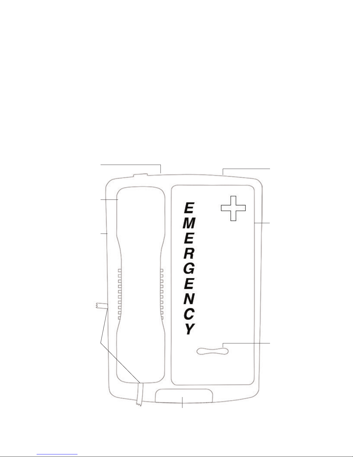
Table of Contents
Aegis-LBE-08 Phone Map 2
2554E Phone Map 3
2510E Phone Map 3
Aegis-LBE-08 4
Package Contents 4
Installation 4
Assembly 4
Features 4
Using the Telephone 4
Data Port 5
Jacks 5
2554E 5
Package Contents 5
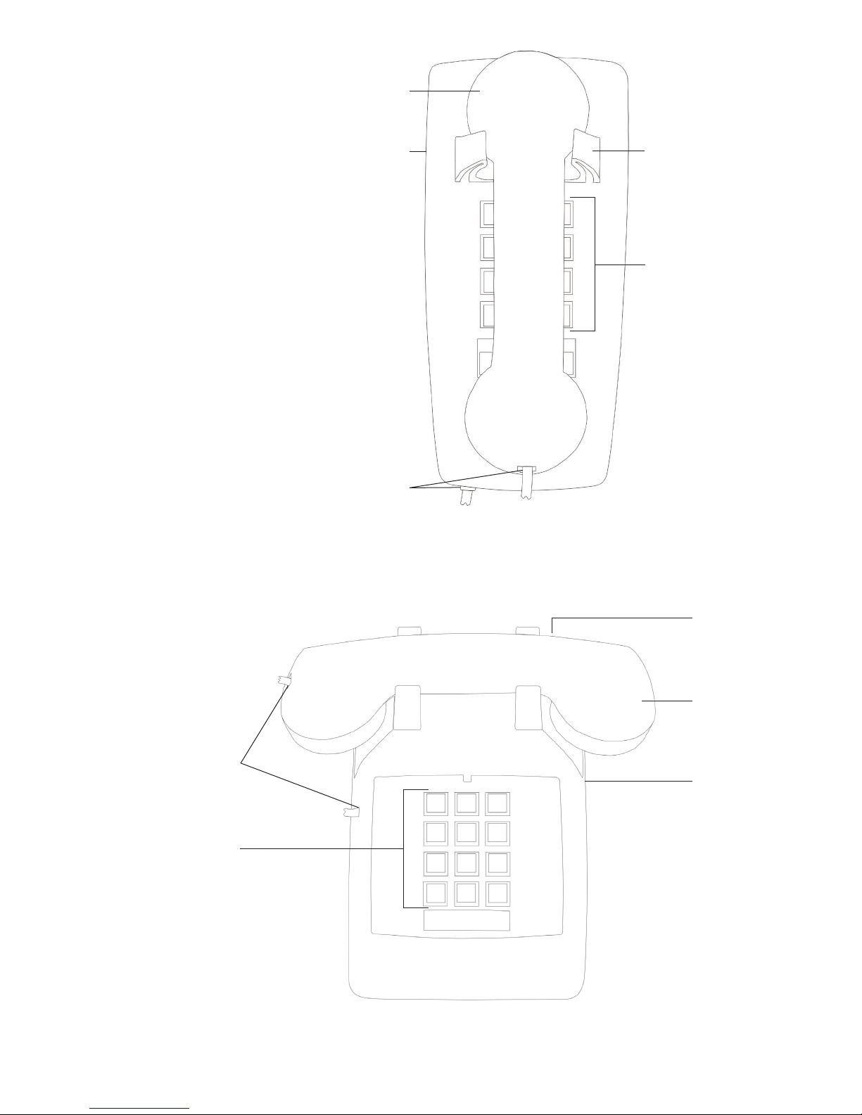
Aegis-LBE-08 Phone Map
Ringer volume control
Handset
Installation 5
Features 5
Using the Telephone 5
Jacks 6
2510E 6
Package Contents 6
Installation 6
Features 6
Using the Telephone 6
Jacks 7
Important Safety Instructions 8
FCC Interference Information 8
FCC RF Radiation Exposure
Statement 9
Industry of Canada Requirements 9
Requirements of Part 15—
FCC Rules 10
Requirements of Part 68—
FCC Rules 10
Care and Maintenance 11
Technical Specifications 11
User Guides 11
Service 11
Statement of Limited Warranty 11
Wall jack
Base
Handset jack
Faceplate
Volume control
2 www.scitecinc.com EMERGENCY SERIES USER GUIDE
Message waiting lamp
2554E Phone Map
Wall jack and Volume control button
on underside of phone
Handset
Base
Handset cradle
Key pad
2510E Phone Map
Volume control button
on underside of phone
Handset jack
Key pad
Handset jack
Wall jack
(on base)
Handset
Base
EMERGENCY SERIES USER GUIDE www.scitecinc.com 3

This telephone user guide details installation,
programming, and operation instructions for
emergency telephone models. Visit the Scitec
website (www.scitecinc.com) for updates to
these and other Scitec products.
AEGIS-LBE-08
Package Contents
• Telephone base unit
• Handset
the handset and line cords. If you will using the
telephone on a desktop, attach the handset.
Features
Dual-Function NEON/LED Message Waiting
Light—Located beneath the voice mail retrieval
touch bar. Compatible with high voltage neon
(90DC Volts) and AT&T/Lucent/Avaya low
voltage LED message waiting light systems (20
to 25DC Volts). Also functions as visual ring
indicator.
• Coiled handset cord
• Straight line cord
Note: Wall-mount bracket sold separately.
Installation
The telephone is designed for use behind a
registered PABX system. The PABX station port
type must be industry standard analog or POTS.
This telephone cannot be used with digital PABX
station ports. The telephone user or installer must
supply a two-wire, RJ-11 modular wall jack to
connect this telephone to the PABX system.
To install the telephone first snap the supplied
coiled handset cord into the jack on the end of
handset. Then place the handset in its cradle.
Connect the free end of the coiled handset cord
to the jack on left side of the telephone body,
marked with a handset symbol. This jack is closer
to the front of the telephone.
Next, take supplied straight modular cord and
insert it into jack on the REAR of telephone.
Connect the other end of this cord to telephone
system wall jack. Lift the handset. A dial tone
should be heard.
Ringer Volume Control Switch—Selects the
volume level of the audible ringer. One of two
volume levels may be selected: LOW or HI.
Volume Control Toggle Key—Selects the volume
level of the handset and speakerphone. Volume
may be set to one of four levels [Normal to
Medium to High to Highest].
Data Port—Provides a convenient extension of
the connected telephone line for connecting a
device such as a modem, fax, or answering
machine.
Hearing Aid-Compatible Handset—ADA/
HAC-compatible.
Handset Holder—Clip located above the
handset cradle. Used in wall mount applications
to conveniently hold an off-hook handset.
Using the Telephone
To Place a Call
Lift the handset, then dial the number desired.
To Answer a Call
Lift the handset.
Assembly
If you will be wall-mounting your telephone, it
is best to do the conversion before connecting
4 www.scitecinc.com EMERGENCY SERIES USER GUIDE
Adjusting the Handset Volume Level
Press the up toggle key to increase the volume
or press the down toggle key to decrease the
 Loading...