


Assembly Instructions
SC5 ASSEMBLY INSTRUCTIONS
SC5 + SC7 + SC Power Install Sheet
Applies to: SC5 (9-7410) + SC7 (9-7400) + SC Power (9-7380)
STEP 1: Install the front stabilizer using two (2) pieces each of the
M10 x 25mm hex head screws, M10 split lock washers, and M10
washers. Repeat this step to attach the rear stabilizer.
STEP 3: Pull down on the seat slider locking pin then slide the
seat assembly onto the seat post installed in Step 2, tightening
the fore/aft adjustment knob to lock the seat slider into place.
NOTE: The fore/aft adjustment knob may need to be loosened.
STEP 2: Install the seat post by loosening the height adjustment
pop pin, then pulling outwards on the pin while sliding the seat
post into the frame.
Fore/Aft
Adjustment
Knob
M8 Washer
Threaded Collar
Locking Nut
Trapezoidal
Locking Nut
STEP 4: Insert one (1) piece of the trapezoidal locking nut into
the handlebar post then slide the handlebar onto the handlebar
post. Next, insert one (1) piece of the threaded collar locking nut
through the handlebar and into the trapezoidal locking nut, tightening with a 10mm allen key. Slide one (1) M8 washer onto the
fore/aft adjustment knob then tighten the knob into the threaded
collar locking nut. Finally, secure the end cap onto the handlebar
post using one (1) piece of the M4 x 10mm screw.
Page 1
620-8607 Rev. A
Assembly Instructions
SC5 ASSEMBLY INSTRUCTIONS CONT.
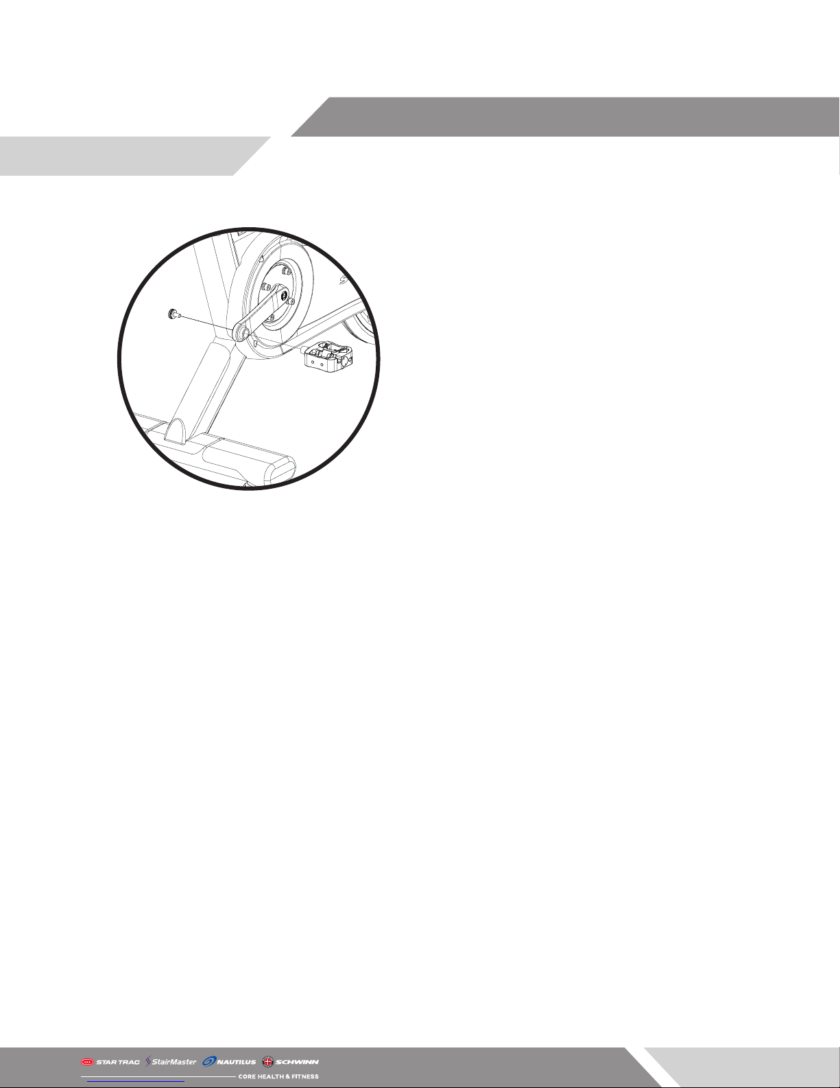
STEP 5: Install the user right side pedal into the crank arm then
use a torque wrench and a 8mm allen socket to secure one (1)
piece of the crank bolt from the other side of the pedal, torquing
to 33-37 ft-lbs (45-50 Nm). Repeat this step for the rider left side
pedal.
NOTE: The pedal MUST be torqued to the above specications
otherwise a failure of the pedal may occur.
Page 2
620-8607 Rev. A
 Loading...