


Core Health & Fitness
Schwinn® S.C. 7
SERVICE
MANUAL
TABLE OF CONTENTS
Click any text to jump to section
PRODUCT SPOTLIGHT ............................................................................................................................................. 3
OTHER MANUALS ............................................................................................................................................. 4
ACCESSORIES ............................................................................................................................................. 5
Cranks & Pedals .......................................................................................... 5
REPLACEMENT PROCEDURES ............................................................................................................................................. 6
Shroud Removal .......................................................................................... 6
Belt Tension & Replacement .......................................................................................... 7
Pairing & Calibrating the 4iiii Crank ........................................................................................ 17
Bottom Bracket Replacement ........................................................................................18
Other Replacement Procedures ........................................................................................22
TROUBLESHOOTING ........................................................................................................................................... 23
Power & Mechanical Issues ........................................................................................23
Console & 4iiii ........................................................................................23
Page 2
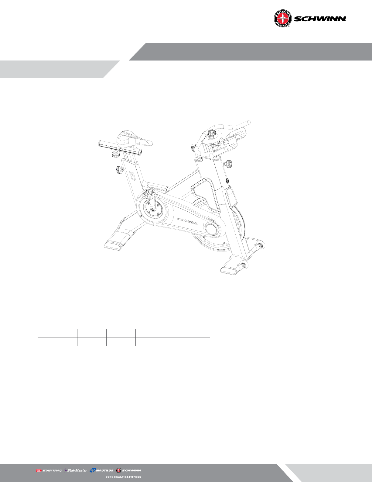
PRODUCT SPOTLIGHT
9-7400 S.C.™ 7
Overall Weight Width Length Height User Weight
120 lbs (54 kg) 21” (53 cm) 55” (140 cm) 46” (117 cm) 0-350 lbs (0-159 kgs)
Product Conformity
• EN957-1 (S,H)
• EN957-10 (S,H)
• ASTM F1250-13
• ASTM F2276-10
All products may be covered by US and Foreign Patents and Patents Pending.
Page 3

OTHER MANUALS
Click the links below to load the related complete manuals from our support website.
Safety warnings and warranty information specic to each unit are located in their respective owner’s manuals.
Manuals
AC Performance (100175)
AC Performance (9-7320)
AC Performance Plus
AC Sport
SC5
SC7
SC Power
IC Classic
AC Power
Related Installation Manuals
• MYE PVS Brackets Installation
Install Owner’s
Consoles
For troubleshooting regarding the consoles available for this bike, chose from one of the service
manuals below:
Manuals
MPower Echelon2G Console
MPower Echelon2 Console
Cadence Pro
Install Service
Page 4
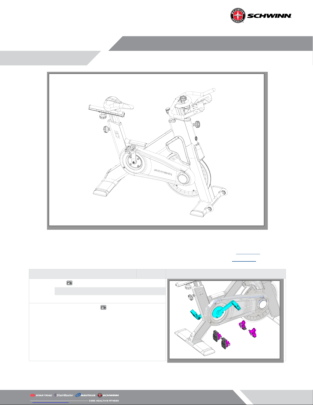
ACCESSORIES
Standard Schwinn pedals have threaded shafts that connect to the crank arms. The right pedal is
right-hand threaded while the left pedal is reverse threaded, meaning you turn to the left to tighten and right to loosen. For pictures of all dierent Schwinn pedals, see document 637-4501 on our
support site. For a comprehensive list of accessories for Schwinn, see document 637-8608.
Cranks & Pedals
Power
Pedals
4iiii
MPower 740-8941
Standard Double Link
Triple Link MT LOOK Delta-compatible
Triple Link MT LOOK Keo-compatible
SKU
718-5765
740-9020
740-8689
718-5869
DELTA
KEO
Page 5
REPLACEMENT PROCEDURES
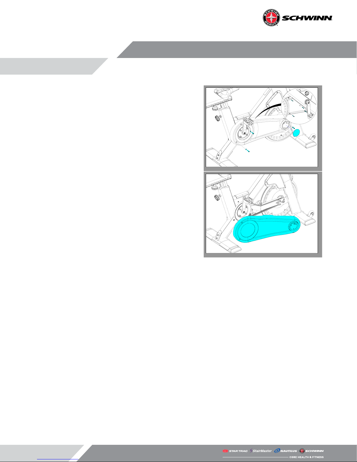
Shroud Removal
1. Remove the rubber chainguard cap.
2. Remove the screws from the user right chainguard (inset).
3. Use a Phillips screw driver and 5mm hex key to remove the
screws securing the user left Chainguard to the bike.
4. Rotate the chainguard downward to remove
Page 6
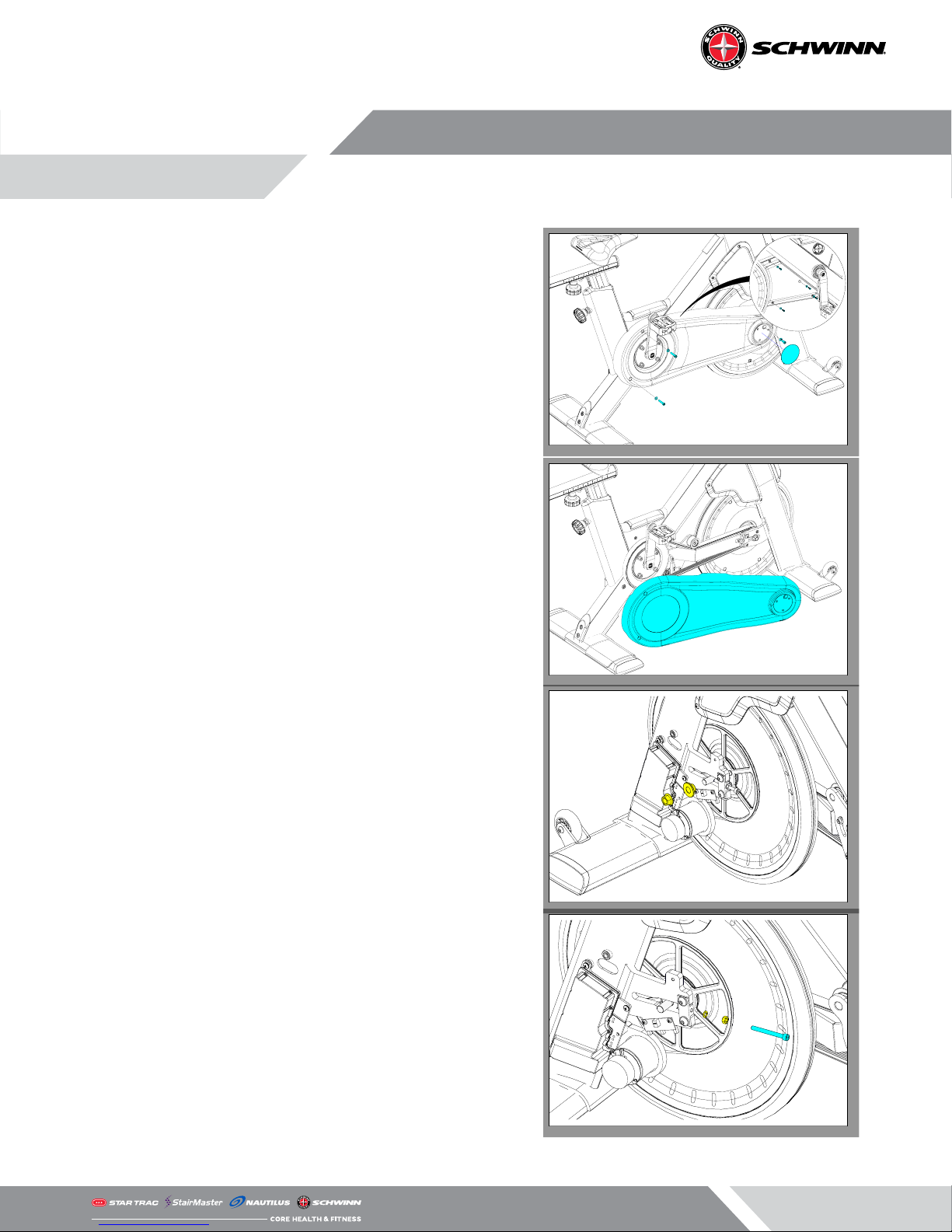
Belt Tension & Replacement
1. Remove the rubber chainguard cap.
2. Remove the screws from the user right chainguard (inset).
3. Use a Phillips screw driver and 5mm hex key to remove the
screws securing the user left Chainguard to the bike.
4. Rotate the chainguard downward to remove
5. Remove the rubber cap from the user left side.
6. Use a 19mm socket to remove the axle bolts and axle spacers on both sides of the ywheel.
NOTE: The axle spacers are left-right specic.
7. Use a small crescent wrench to loosen the tension screw
lock nuts on both sides of the ywheel.
8. Use a 3mm allen key to remove the left and right tension
screws.
Page 7
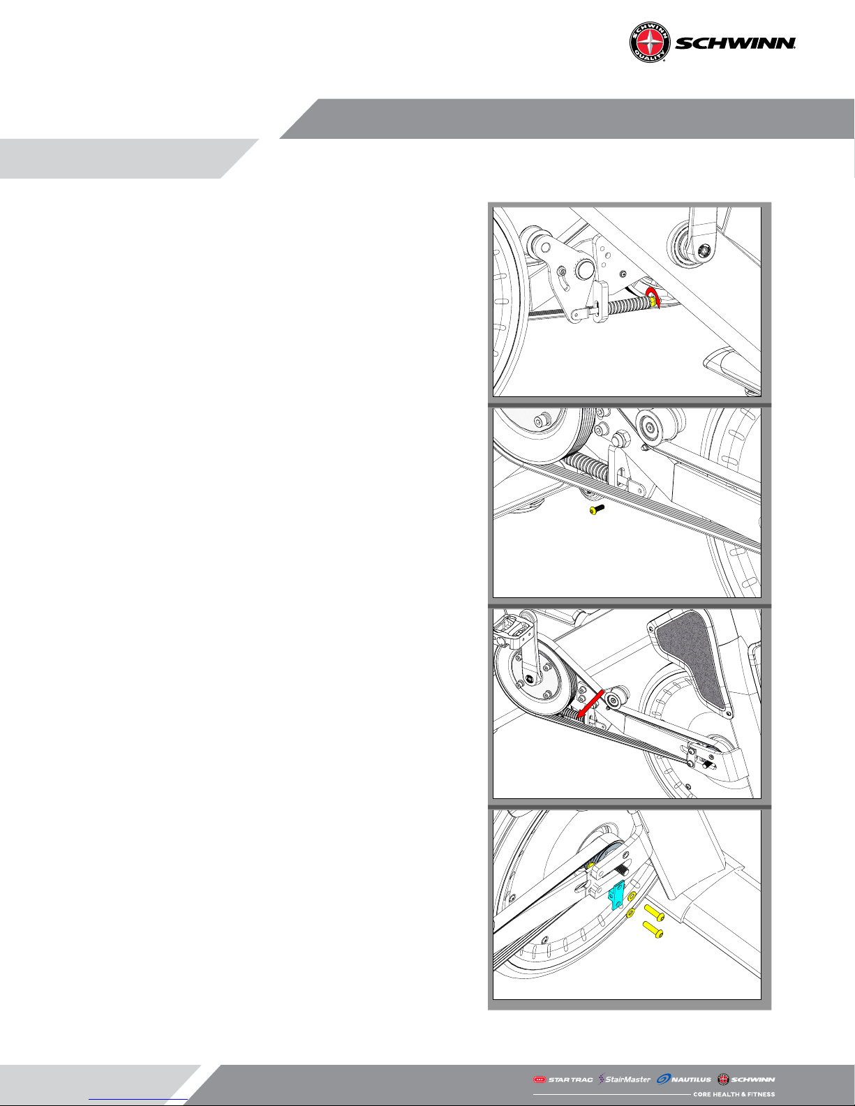
9. Use a 13mm open-ended wrench to loosen the belt idler
tension spring.
10. Use a 3mm allen key to remove the screw connecting the
idler to the tensioner arm.
11. Carefully walk the belt o of the tensioner pulley then walk
the belt o of the crank pulley.
12. Use a 3mm allen key and a 13mm open-ended wrench to
remove the two (2) screws and nuts connecting the cross
brace to the front right fork. Repeat this step for the other
side.
Page 8
 Loading...