

Page 1

Core Health & Fitness
MPower™ Echelon2G Console
ASSEMBLY
MANUAL
Page 2
Required Tools:
• #2 Phillips Screwdriver
• 2.5mm Allen Key
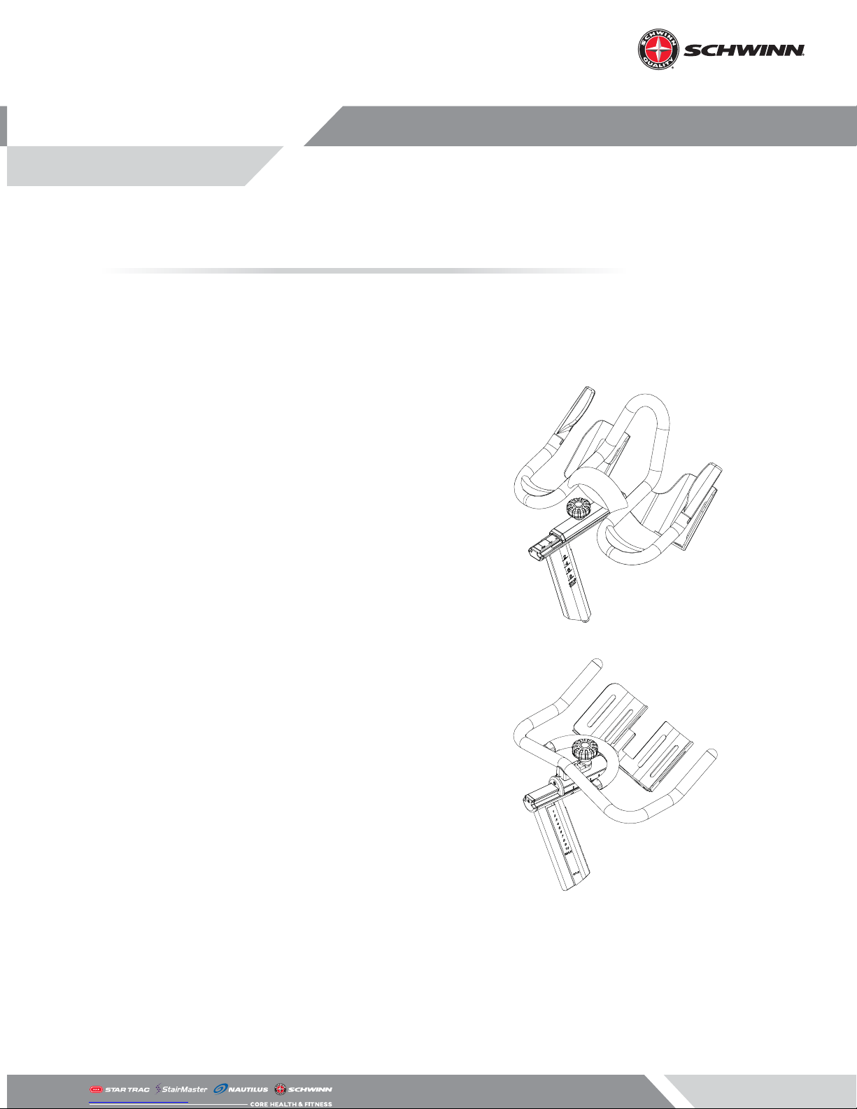
1. Identify which handlebar style is present on the
bike. If the handlebars are the Performance-style
(pictured right), please proceed to Page 2 - Step
1. Otherwise, please continue to Step 2.
Echelon2G Assembly Manual
Applies to: Echelon2G
2. If the handlebar style present on the bike is the
Studio-style handlebars (pictured right), please
proceed to Page 4 - Step 1.
Page 1
Page 3

1. Use a #2 phillips screwdriver to secure the console bracket to the handlebars using three (3)
pieces of the M4 x 10mm screws.
2. Slide the console onto the console bracket, then
secure the console to the bracket using one (1)
piece of the M3 x 6mm screw.
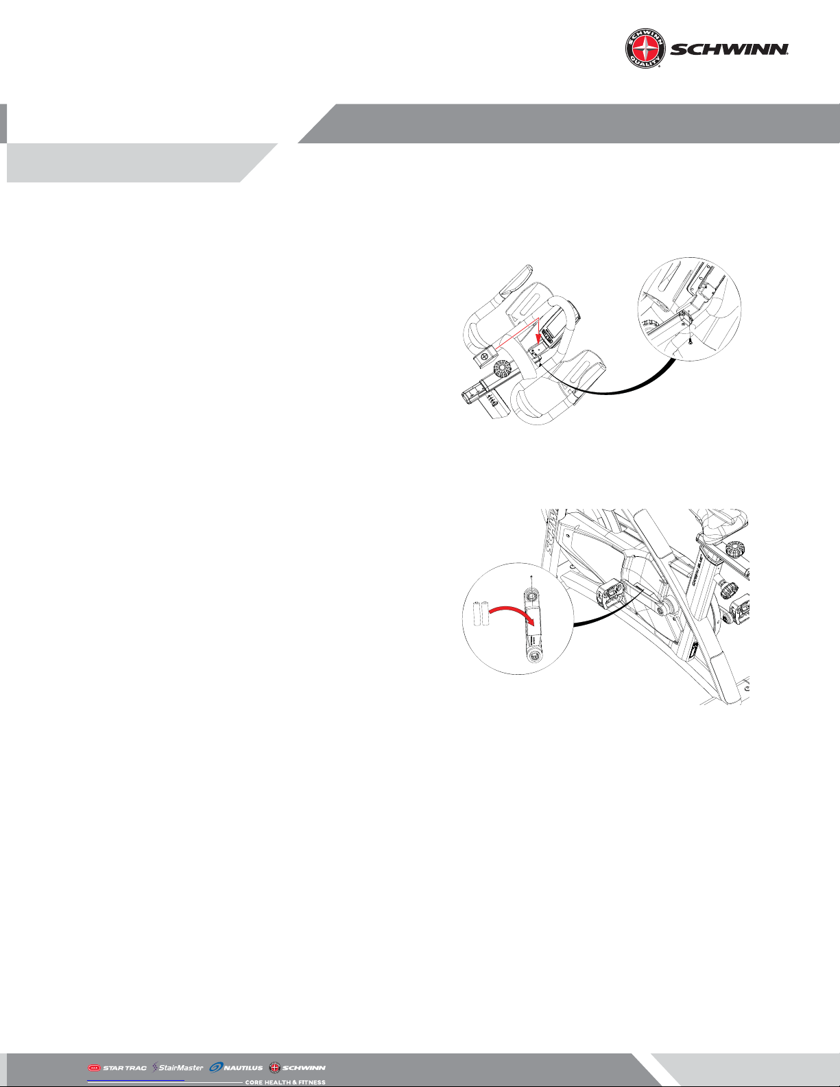
3. Plug the console data cable into the back of the
console, insert the strain relief grommet into the
strain relief cover, then use a 2.5mm allen key to
attach the strain relief cover to the console bracket using two (2) pieces of the M3 x 12mm screws.
Page 2
Page 4
4. Attach the console bracket cover to the console
bracket using one (1) piece of the M5 x 16mm
screw.
5. Open the 4iiii Powermeter battery compartment
on the user left side crank arm using a #2 phillips
screwdriver, then install the two AA batteries.
6. After completing this step, please proceed to
Page 6 - Step 1.
Page 3
Page 5

1. Use a 2.5mm allen key to secure the console
bracket to the handlebars using four (4) pieces of
the M4 x 14mm screws.
2. Use a #2 phillips screwdriver to secure the bracket cover to the bracket using one (1) piece of the
M5 x 16mm screw.
3. Slide the console onto the console bracket, then
secure the console to the bracket using one (1)
piece of the M3 x 6mm screw.
Page 4
Page 6

4. Plug the console data cable into the back of the
console, insert the strain relief grommet into the
strain relief cover, then use a 2.5mm allen key to
attach the strain relief cover to the console bracket using two (2) pieces of the M3 x 12mm screws.
NOTE: Ensure that the hole for the data cable is facing upwards, otherwise the data cable will interfere
with installation of the console bracket cover.
5. Open the 4iiii Powermeter battery compartment
on the user left side crank arm, then install the
two AA batteries.
6. After completing this step, please proceed to
Page 6 - Step 1.
Page 5
Page 7

1. Ensure that the 4iiii crank is up to date. To do this,
heck that Bluetooth is enabled on the phone
then follow the proceeding directions.
2. Download the 4iiii app from the app store BUT
DO NOT CREATE A LOGIN.
3. Record the ANT+ ID of the powermeter that
needs to be updated.
NOTE: The ANT+ ID is a 4 OR 5 digit number located
on the underside of the 4iiii sensor. If the number is 4
digits, the rst number of the ANT+ ID is zero (0).
Android
iOS
Page 6
Page 8

4. Open the 4iiii app and select the “Pro le” menu
in the upper left corner of the main screen then
select “PRECISCION Con guration”
5. Spin the 4iiii crank arm of the target bike >30
RPM; the 2-5 digit ANT+ ID should show up on
the “Select your Powermeter” screen.
6. Select the corresponding ANT+ ID of the bike
from Step 5 and set up the powermeter as “Single
Sided.”
Page 7
Page 9

7. On the next screen, a rmware update prompt
should appear if newer rmware is available.
Select “Upgrade” to begin the update.
8. The update procedure will now run. This may
take several minutes to complete.
Page 8
Page 10

9. Once the update is complete, select “Continue.”
10. Enable the “3rd Party Apps” option.
11. Select “Forget” to disconnect from this powemeter once the rmware has been updated.
12. On the Echelon2G console, press and hold
STAGE and “AVG/MAX” for 3-5 seconds to
access the service menu.
13. Use AVG/MAX to scroll until SENSOR TYPE is
displayed then push the back-light button to
access the sensor menu. Ensure that “4iiii” is displayed as the sensor type.
Page 9
Page 11

14. If the sensor type is set to “Echelon 2” press the
back-light button to select the sensor type,
use the AVG/MAX button to select “4iiii” then
press the back-light button again.
15. Once “4iiii” is selected the console will enter the
pairing process, check the side of the power sensor for a 4 OR* 5-digit ANT+ ID code. Enter this
code on the “ENTER ANT ID” screen using AVG/
MAX to scroll and the back-light to enter the
ANT+ ID.
16. Once the ANT+ ID has been entered, pedal the
bike, then select “PAIRING SPIN CRANK” but pushing the back-light button . If pairing does
not pass, check to ensure the ANT+ ID is correct
and try the pairing process again. It may take 2-3
attempts to pair successfully.
17. After successfully pairing the 4iiii crank, the power sensor must be calibrated BEFORE riding the
bike. Press and hold STAGE and AVG/MAX for
3-5 seconds to access the service menu then use
AVG/MAX to scroll until “CALIBRATE” is displayed
then select it using the back-light button .
“ZERO RESET” will be displayed, press the backlight button to select it. Once “SPINCRANK”
is displayed, spin the crank and press the backlight button to proceed. Ensure that the left
crank arm is in the 6 o’clock position then follow
the on-screen directions to nish calibrating the
sensor.
Please note that the ANT+ ID referenced in Step
4 could be either a 4-digit OR 5-digit number.
If the 4-digit code is present, the rst number of
the ANT+ ID Code is zero (0).
Page 10
Page 12

© 2018 CORE HEALTH & FITNESS, LLC PART NUMBER 620-8594, REV D
 Loading...