

Schwinn MPower Echelon2 Service Manual

Core Health & Fitness
Schwinn Echelon2
SERVICE
MANUAL

By following the enclosed instructions and maintenance schedule, you will extend the life of your bikes and help ensure
the equipment will function properly during use.
Before working on this equipment, pay attention to the following warnings:
• Read and understand the complete Owner's Manual.
• Keep Owner's Manual for future reference.
• Read and understand all warnings on this machine. If at any time the Warning stickers become loose, unreadable or dislodged, contact Customer Service for replacement stickers.
• Keep children away from this machine. Monitor them closely when near the machine. Parts that move and appear dangerous to adults can appear safe to children.
• Consult a physician before you start an exercise program. Stop exercising if you feel pain or tightness in your
chest, become short of breath, or feel faint. Contact your doctor before you use the machine again. Use the
values calculated or measured by the machine's computer for reference purposes only.
• Before each use, examine this machine for loose parts or signs of wear. Do not use if found in this condition.
Monitor the Seat, Pedals, and Crank Arms closely. Contact Customer Service for repair information.
• Maximum user weight limit: 350lbs. (159kgs). Do not use if you are over this weight.
• Do not wear loose clothing or jewelry. This machine contains moving parts.
• Set up and operate this machine on a solid, level, horizontal surface.
• Do not step o the machine until the Pedals have fully stopped. Use the Resistance Adjustment Knob to slow
the Pedals to a controlled stop before you step o the machine.
• Do not operate this machine outdoors or in moist or wet locations.
• Keep at least 19.7"(0.5m) on each side of the machine clear. This is the recommended safe distance for access
and passage around and emergency dismounts from the machine. Keep third parties out of this space when
machine is in use.
• Do not over exert yourself during exercise. Operate the machine in the manner described in this manual.
• When the machine is put in a studio or club environment, it can only be used in areas where access and control
of the machine is managed by approved sta. The degree of management depends on the user's ability to recognize and prevent danger to third parties during the exercise movement.
Tools Required
The tool list below is needed to repair and perform preventative maintenance on all Schwinn bikes.
• PEDAL WRENCH
• CRANK ARM REMOVAL TOOL
• ISIS DRIVE BB TOOL (BBT-18)
• SMART RELEASE REMOVAL TOOL
• CRANK ARM REMOVAL TOOL
• 3/8 DRIVE RATCHET (QTY 2)
• 3/8 DRIVE EXTENSION (3 INCHES)
• 14MM SOCKET 3/8 DRIVE
• 15MM SOCKET 3/8 DRIVE
• 21MM OPEN ENDED WRENCH
• LONG PHILLIPS SCREW DRIVER
• STANDARD PHILLIPS SCREW DRIVER
• ½ DRIVE RATCHET
• 3MM T HANDLE ALLEN HEAD
• 26MM SOCKET ½ DRIVE SOCKET
• 5/16 ALLEN HEAD SOCKET 3/8 DRIVE
• 17MM OPEN ENDED WRENCH
• 5/32 ALLEN HEAD SOCKET 3/8 DRIVE
• 14MM OPEN END/BOX END WRENCH
• 6MM ALLEN HEAD SOCKET 3/8 DRIVE
• 8MM ALLEN HEAD SOCKET 3/8 DRIVE
• 10” CRESCENT WRENCH
• CHAIN WEAR INDICATOR
• TEFLON SPRAY
• WHITE LITHIUM GREASE
Page 2

Echelon2 Console
Ɣ What’s in the Box
Ɣ General Features/Functions
Ɣ Installation
of the Schwinn® Echelon2 Console System
Ɣ Zeropoint Calibration Procedure
Ɣ Echelon2 Post-Install Checklist
Ɣ Power Validation Table
Ɣ Menu Map
Ɣ Wiring Diagram
and Signal Flow
Ɣ Preventative Maintenance
Ɣ Troubleshooting
- Console Not Displaying RPMs
- Console Not Displaying Watts / Power / Calories
- Watts / Power is too low/high
and Service
Ɣ FAQ s
- Loading Firmware
- Setting a Passcode
Page 3

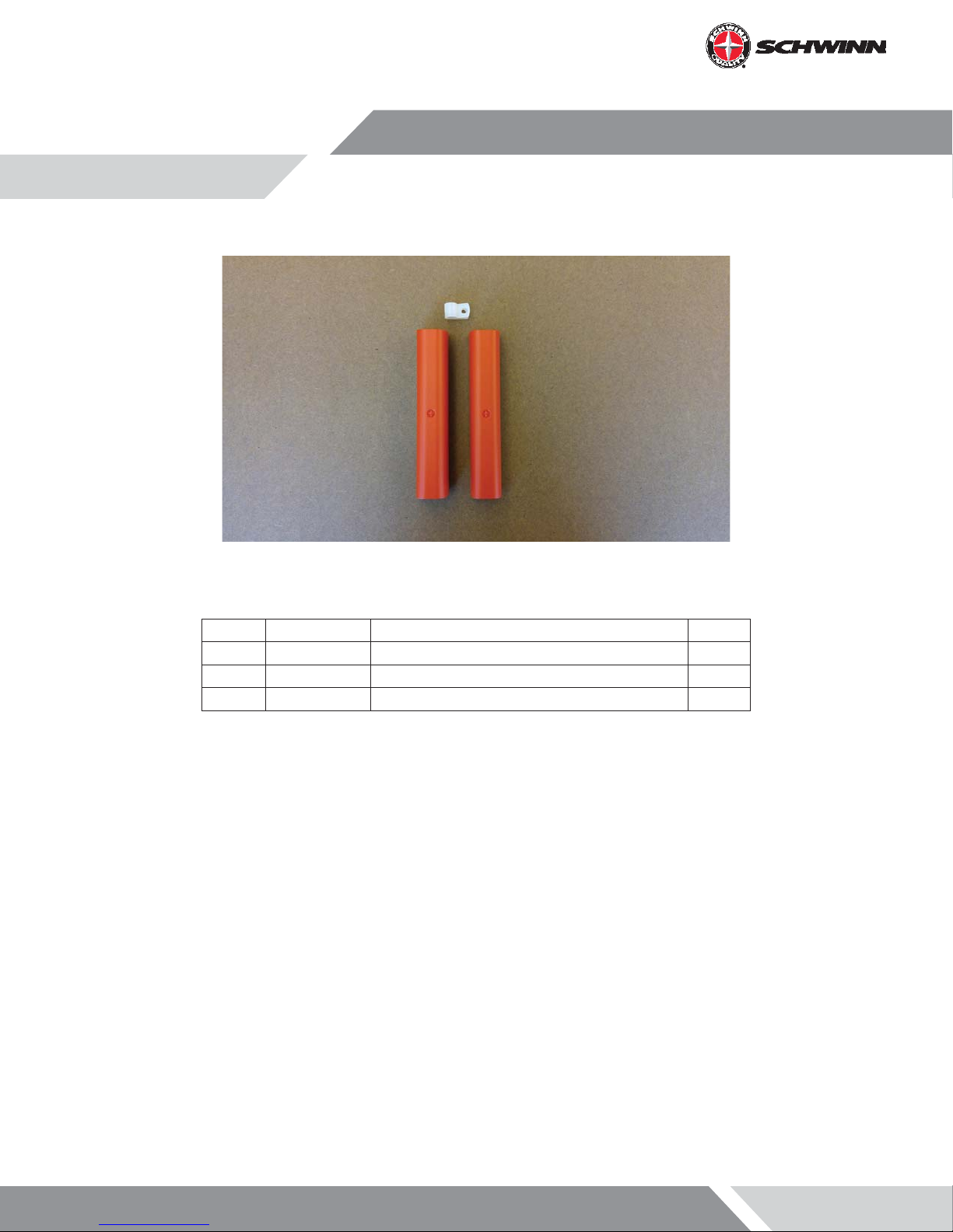
What’s in the Box?
SCHWINN® Echelon2 (Part #740-8727)
Package includes components listed below
Index Part Number Description QTY
1 740-8727 SCHWINN® Echelon2 N/A
1.1 110-3640 SCREW, PHP, M4x0.7x10, SS 3
1.2 110-3641 SCW-BHCS M5x0.8x14 SS 2
1.3 110-3642 SCREW, M3X0.5,12mm, SHC, HK, SS,GR 8.8 2
1.4 110-3643 SCREW, M3X0.5,6mm,RHM,PH,SS 1
1.5 140-3585 KIT,WIRE SADDLE CLIP, ECH 2 1
1.6 740-8727 016 BOX, MPOWER Q 1
1.7 740-8822 SRB, MPOWER Q, RECTANGLE HOLE 1
1.8 740-8925 ASSY, SCHWINN® Echelon2,COMPUTER 1
1.9 740-8926 SPEED SENSOR ASSY, WIRED 1
1.1 740-8927 COSMETIC CAP ASSY 1
1.11 740-8928 RJ45 2-PIN LONG CABLE 1
1.12 740-8929 MOUNT, M POWER Q 1
1.13 740-8930 SRB MOUNT, M POWER Q 1
1.14 740-8938 CD,OWNERS/INST MANUAL,ECH 2C7 1
Page 4

SCHWINN® Echelon2 Power Upgrade Kit (Part #740-8730)
Package includes components listed below
Index Part Number DESCRIPTION QTY
1 740-8730 SCHWINN® Echelon2 POWER UPGRADE N/A
1.1 110-3644 SCREW, M4X0.7X14, BHSC,HE,SS 3
1.2 740-8607 CALIBRATION TOOL, ZERO POINT, ACPP 1
1.3 740-8730-005 POWER SENSOR UPGRAGE PACKAGING 1
1.4 740-8931 POWER UPGRADE CABLE, RJ45 1
1.5 740-8932 2-PIN SHORT SPEED SENSOR CABLE 1
1.6 740-8933 ASSY, MAGNET, SENSOR, ECH 2 1
1.7 740-8934 ASSY, ECH2 POWER 1
1.8 740-8935 PAD,RUBBER,POWER SENSOR 1
Page 5
SCHWINN® Echelon2 External Wire Kit (Part #740-8875)
Package includes components listed below
Index Part Number Description QTY
1 740-8875 KIT, EXTERNAL WIRE, Echelon2 N/A
1.1 740-8875_001 EXTERNAL CABLE COVER ASSY 2
1.2 740-8875_005 CABLE CLAMP 1
Page 6
Echelon2 Features and Functionality
The Echelon2 provides riders with real-time user metrics that can be used to improve the current and future workouts.
Watts, time, kcal, distance, RPMs, speed, distance, and heartrate are displayed on an intuitive display that allows for ease
of use during high intensity rides.
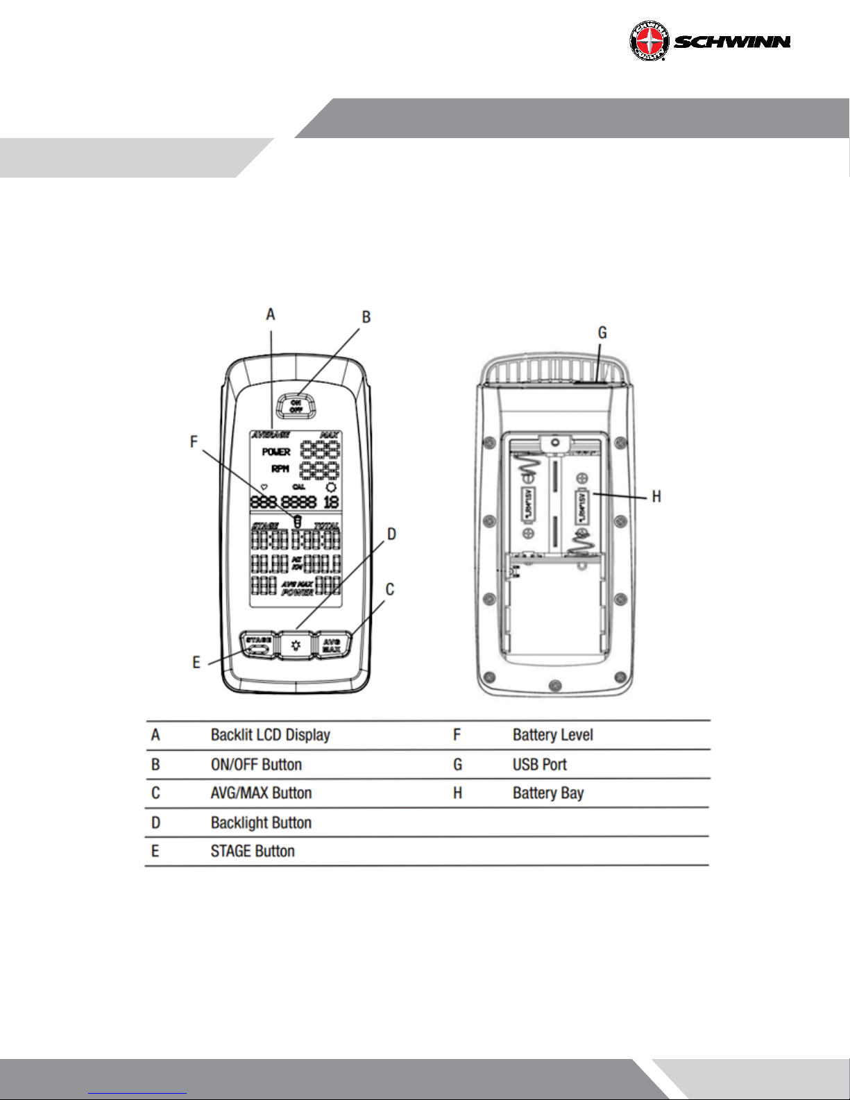
Backlit LCD Display
During the workout, the multi-function, backlit LCD shows your workout measurements, results, user setup data and
console diagnostics.
To turn on the backlight, push the Backlight button. The backlight turns o after 10 seconds to conserve the batteries.
This backlight setting can be adjusted in the Service menu.
Page 7

Heart Rate Monitor
The console receives heart rate data from the heart rate monitor (HRM).
The console can read heart rate data from an ANT+ 2.4GHz or Polar® compatible 5kHz wireless chest strap.
• ANT+ 2.4GHz Wireless: The ANT+ 2.4GHz Wireless Heart Rate Monitor (HRM) sends heart rate data to the console
after proximity linking automatically occurs after console startup. The console can read the HRM data to a distance of 118” (3 m) during Workout Mode. If you have a compatible paired ANT+ Sport Watch and ANT+ HRM,
the console links with the Sport Watch and reads the heart rate data from it, if the watch is compatible. The
Schwinn console uses the ANT+ Fitness Prole. Visit
www.thisisant.com for a directory of compatible devices
• Standard EM 5kHz Pulse: The console uses the EM (electromagnetic) 5kHz pulse wireless protocol to read heart
rate data from the standard heart rate monitors (HRMs), such as a Polar® transmitter chest strap.
Workout Data Storage
The console sends workout data to the user’s data storage device -- for example, a USB ash memory device or a sport
watch.
• ANT+ Sport Watch for Data Storage: During Workout Mode the console sends workout data to the ANT+ Sport
Watch. When the proximity linking is complete, the watch and console can send and read data up to 118” (3 m).
Visit
www.thisisant.com for a directory of compatible devices.
• USB Interface / Data Storage: During Workout Mode the console sends workout data to the USB device:
• Workout (total) -- Time, Distance, Calories, Power, RPM, Avg Power, Max Power, Avg
• Workout Stages -- Time, Distance, Avg Power, Max Power, MAX RPM. Consoles with rmware V1.1
and later will also report AVG and MAX heart rate for each stage.
NOTE: If you connect the USB device after the workout ends, the console only sends the Total Summary data to
the USB device. Workout Data is stored as a .csv le with the name MPOWERXX.csv, where XX is the two-digit
number from 1 to 99. The console will automatically save using the next available number on the USB device if
les are already present.
The USB port also gives access to update the console rmware by a Service Technician. There is a USB symbol that will
ash next to the RPM when the console is uploading data to the USB stick. The stick must remain in the plug as long as
the USB symbol ashes. Once the symbol stops ashing, the stick can be removed.
Page 8
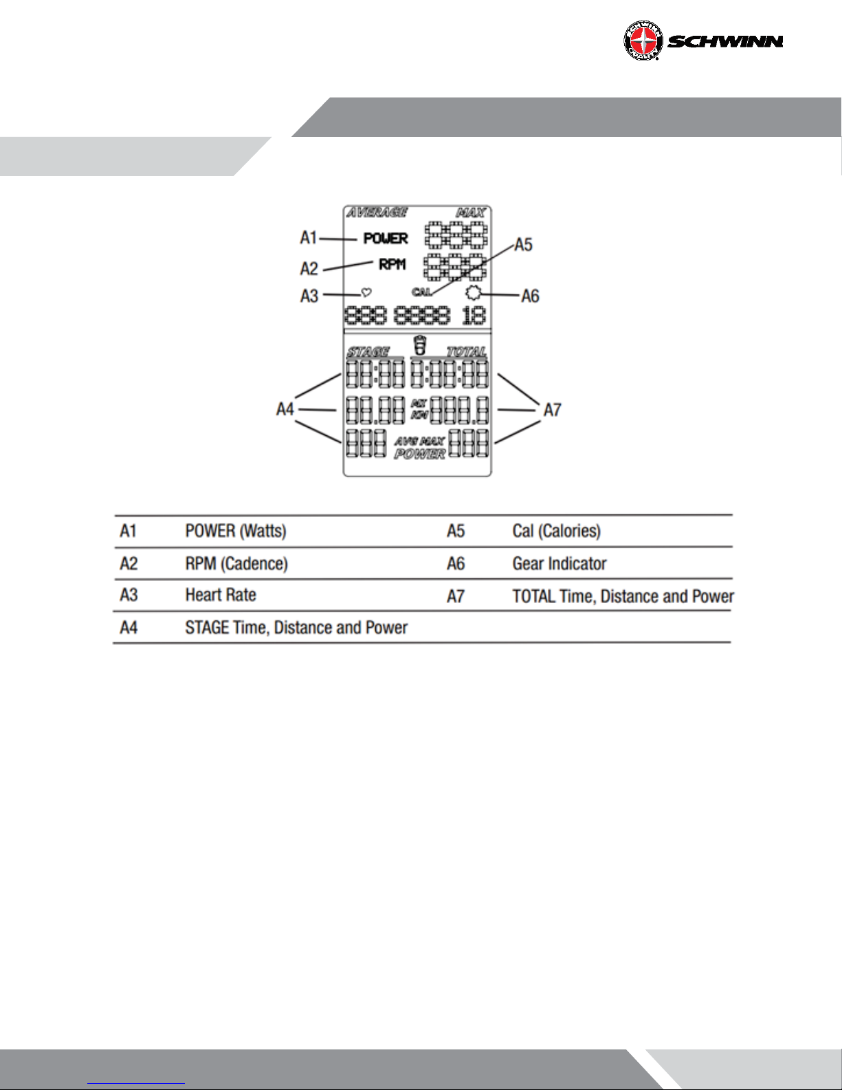
Power
The power display eld shows the Power in Watts that you are producing at the current resistance level (1 horsepower =
746 Watts). Power data only shows if there is a power sensor installed on the bike.
RPM
The RPM display eld shows the current pedal revolutions per minute (RPM).
Heart Rate
The Heart Rate display eld shows the heart rate in beats per minute (BPM) from the heart rate monitor (HRM). When
the computer is ON, it will search for a signal from a compatible heart rate strap for 30 seconds. During this time, the
HR symbol will ash. If a strap is detected, the HR symbol will stop ashing and remain solid while displaying the HR. If
a signal is not detected after 30 seconds, the HR symbol will disappear. The user may reinitiate the pairing process by
pressing and releasing the ON/OFF button.
Page 9

Heart Rate Note: The heart rate monitor is not a medical test, nor is it designed as a medical test. It is simply a guide
to target heart rate training. Please consult with your physician prior to engaging in any strenuous physical activity.
Schwinn does not warranty the heart rate system performance on this product, as the heart rate system performance
various based on a user’s physiology, tness level, age, method of use, and other factors.
Calories
The Calories display eld shows the estimated calories that you have burned during the exercise. This value is calculated
based on POWER if a Power Sensor is installed. Calories are not calculated if a power sensor is not installed. Consoles
with rmware V1.1 or later have to ability to turn the CAL display OFF in the service menu.
Workout Stage
The STAGE display eld shows the time, distance and AVG/MAX power in the current Stage of the workout. Time and
distance values start at zero and count forward until the end of the Stage. Power is averaged for the current stage.
Gear
The gear display eld shows a number from 0-36 indicating resistance level. The gear display can be turned OFF in Service Mode.
Workout Totals
The TOTAL display eld shows the total time, distance and avg/max power for the entire workout period.
Keypad
The multi-function keypad lets you set the console measurements for your workout, see and update your workout data,
and examine the console diagnostic messages. Tap the ON/ OFF button to activate the console from Sleep Mode. The
Operations section of this manual gives you the procedures for using the buttons in each Operations mode. The Backlight button sets your selections during the ride and in Service Mode.
Battery Level
The Battery Level icon shows the battery level for the console. All four segments of the icon are on when the battery
level is high. When the battery level is low, only the bottom segment is on. The bottom segments ashes when battery
level is very low.
Page 10
If the battery level is too low to continue operation, the console display ashes the message “LO batt” and the console
goes into Sleep Mode. If this occurs during a workout, the workout stops and the console display shows the workout
results for 10 seconds. Then the “LO batt” message displays and the console goes into Sleep Mode.
Bike Sensor Data
The console receives data from the bike’s sensors and uses the data to calculate workout results.
- RPM Sensor: The Schwinn® console comes with a RPM sensor for the bike. This sensor transmits data from
the ywheel to the power sensor and the console.
- Power (Watts) Sensor: The Power sensor is an optional upgrade. The power sensor calculates rider Power
(Watts) production from the brake resistance mechanism.
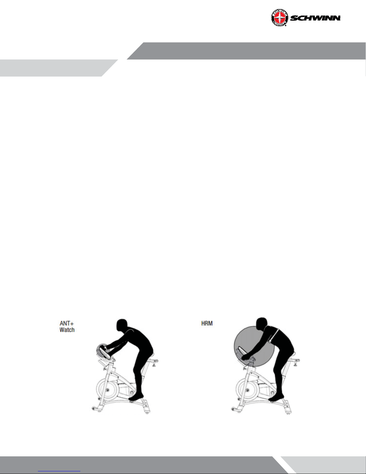
Pause Mode
During the ride, the console collects user data to calculate and record workout data. Proximity linking to the user’s HRM
or ANT+ watch also automatically occurs after console startup..
Use the appropriate instruction for monitoring equipment.
- USB storage device --install the device in the USB port.
- ANT+ watch --link to the console. Move the watch to 2”-4” (5-10 cm) or less from the ANT+ Link Here icon on
the console and hold it there until proximity linking is complete.
- ANT+ HRM --link to the console. Lean into the console so that the HRM is 7.5”-31” (20-80 cm) from the ANT+
Link Here logo, until a value is displayed.
Note: If you have an ANT+ Sport Watch and paired ANT+ HRM, it is only necessary for the console to link
with the sport watch. However, if you have an ANT+ Sport Watch and EM 5kHz HRM, the console links to
the watch and the HRM. Visit
sole uses the ANT+ Fitness prole.
www.thisisant.com for a directory of compatible devices. The Schwinn con-
Page 11
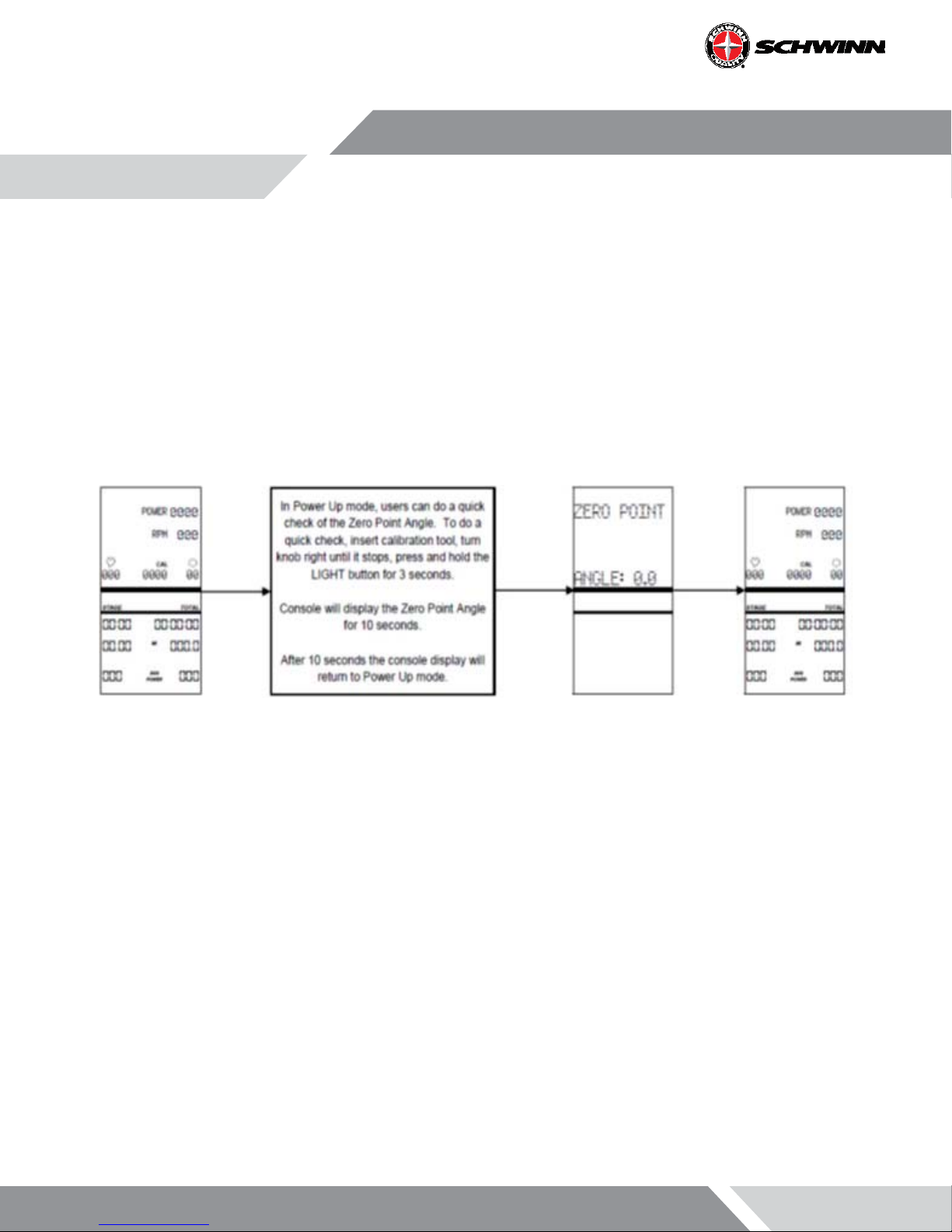
Zeropoint Current Angle Quick Check
Software V1.7 adds a new feature that allows users to quickly check the current angle of the Zeropoint Calibration from
the main Ride menu. The enables riders to quickly check to verify the sensor is still calibrated without having to navigate
through the service menu.
To do the quick check:
1. Place the calibration tool on the ywheel.
2. Turn the brake knob clockwise until the brake stops.
3. From the main Ride menu, hold the LIGHT button for 3 seconds.
The console will display the Zeropoint angle for 10 seconds, after the 10 seconds the console will return to the main
Ride menu..
Page 12
Installation of the Schwinn® Echelon2 Console System
Tools Required:
- Phillips Screwdriver
- 2.5mm Allen Key
- 3mm Allen Key
- Soft-jaw Pliers (pliers with protective rubber or plastic covering jaws)
WARNING: Do not use power tools for any part of the installation of the console, power sensor, or related components. Power tools may cause irreparable damage by over torquing the screws and damaging components
such as plastic components. Also over torquing screws with hand tools can cause damage to plastic components, or strip the heads of the hardware.
AC Sport™ and AC Performance™ Installation
NOTE: If installing the console with the optional power upgrade at the same time as the console, review the
instructions in the section “Optional Power Upgrade Kit Installation on AC™ Sport and AC™ Performance Bikes”
before proceeding with the steps in this section.
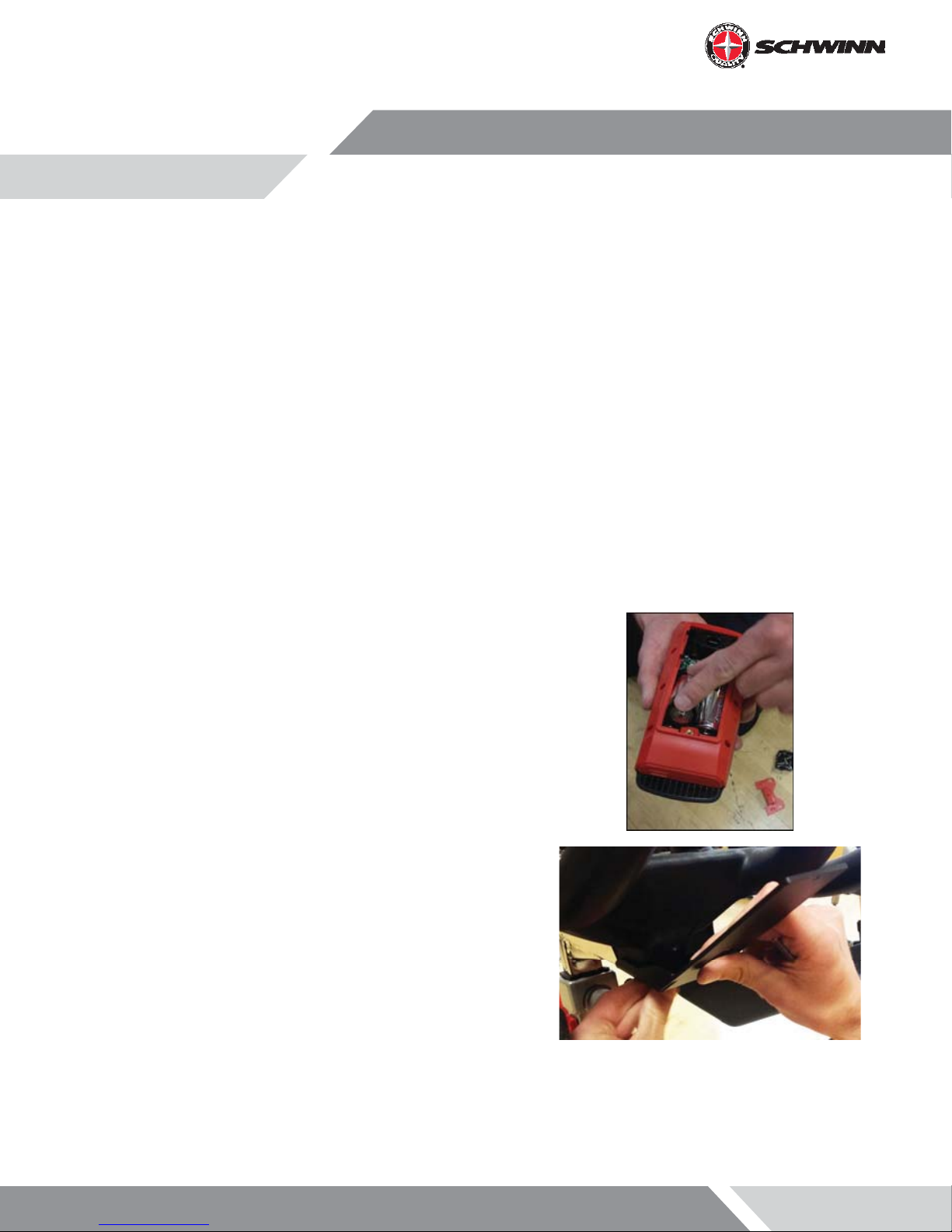
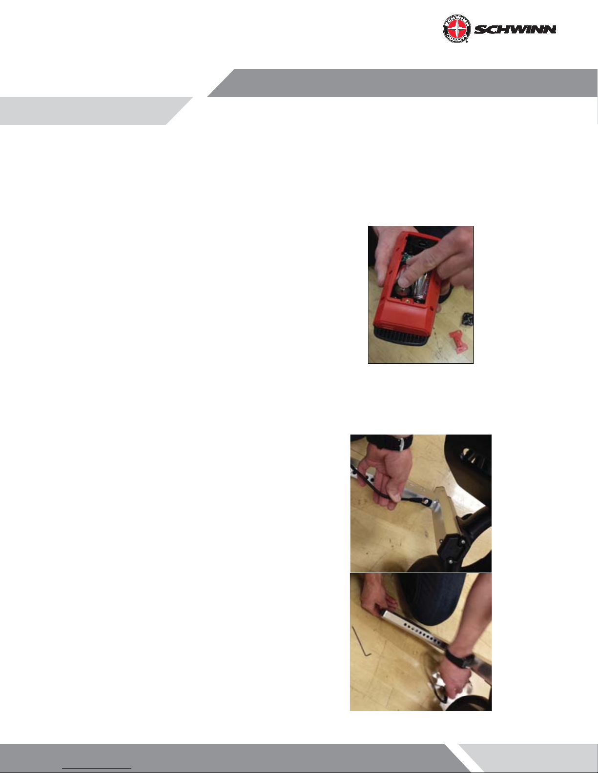
1. Insert batteries into console
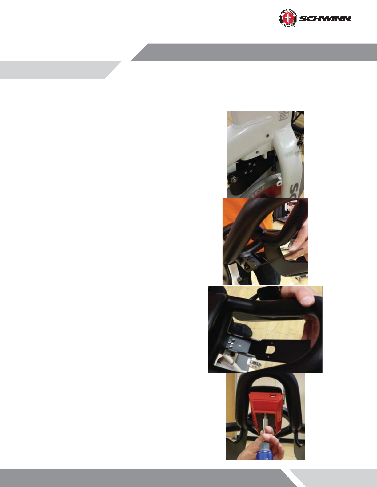
2. Mount the console bracket using the two (2) M5 x 14mm button head screws.
Page 13
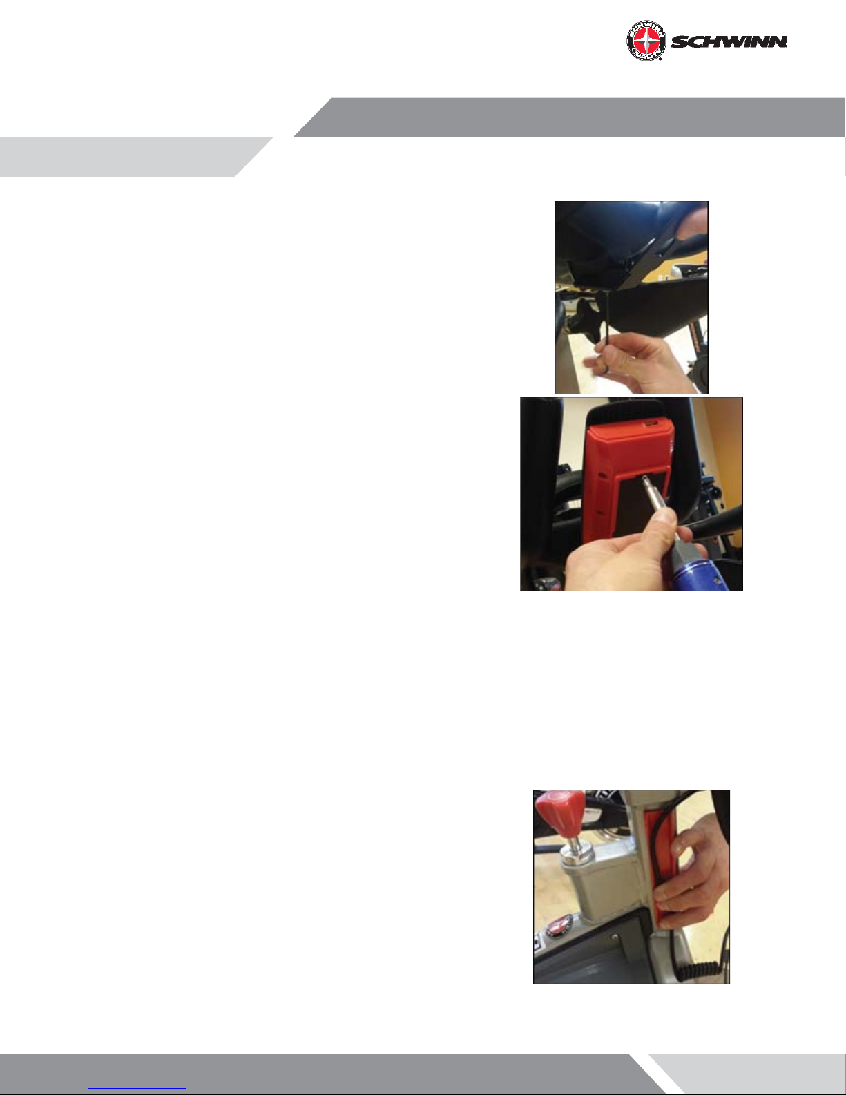
3. Tighten the screws using the 3mm hex key
4. Slide the console onto the bracket. Insert the M3 x 6mm pan
head screw and tighten with the screw driver
5. Prior to installing the upper conduit, clean head tube with
isopropyl alcohol. Allow to air dry.
6. Peel o backing adhesive and align duct part number 7408875-001 to forward edge and lower edge of the frame tube.
Apply normal pressure for 5 seconds
Note: It is recommended that the adhesive set for 24 hours
before use.
7. Insert the cable through the slot
Page 14

8. Snap the outer part of the cable duct onto the base with the
cable inside
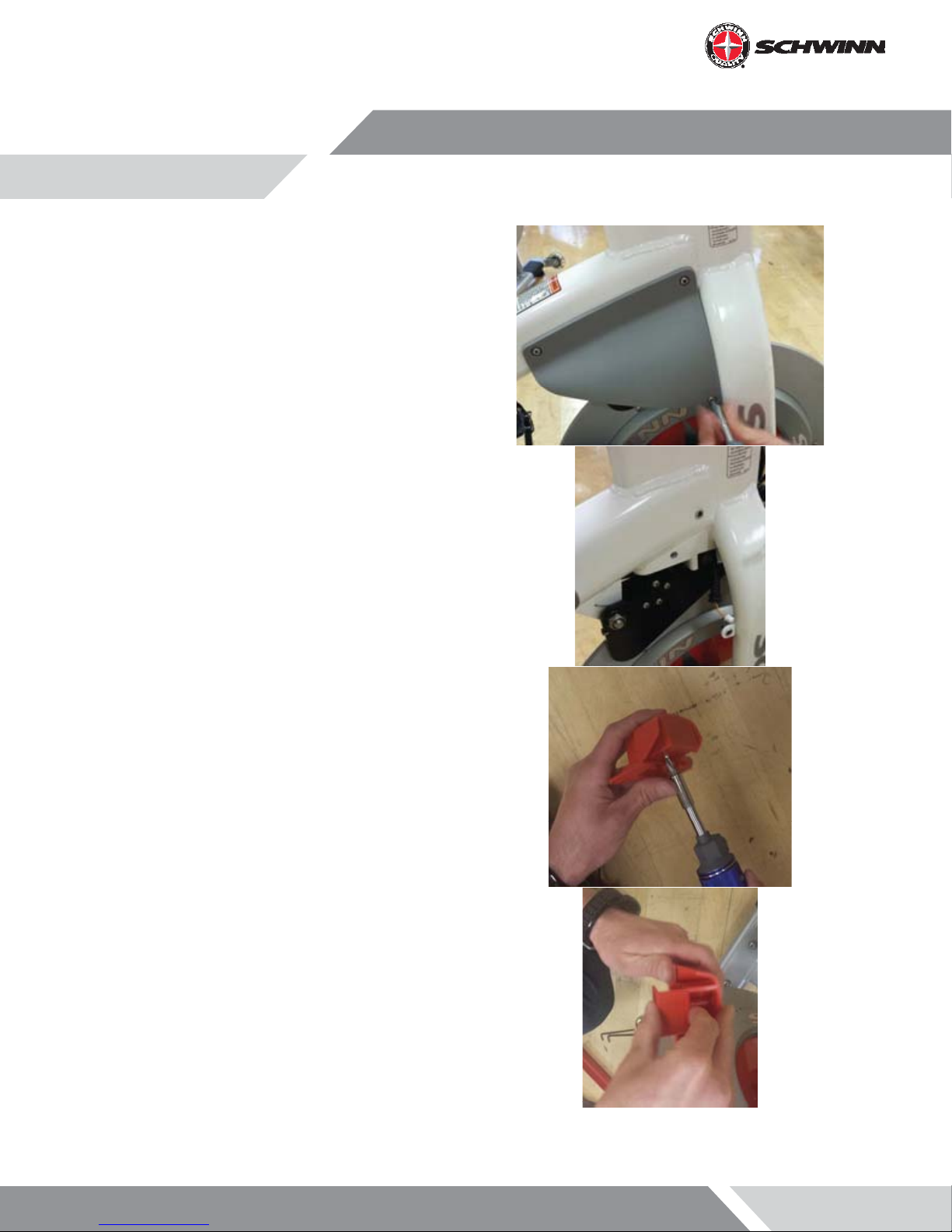
9. Using a philips screw driver, remove the sweat guard (Do not
use a power drill in removing and re-installing)
10. Route the cable through the sweat guard
Page 15
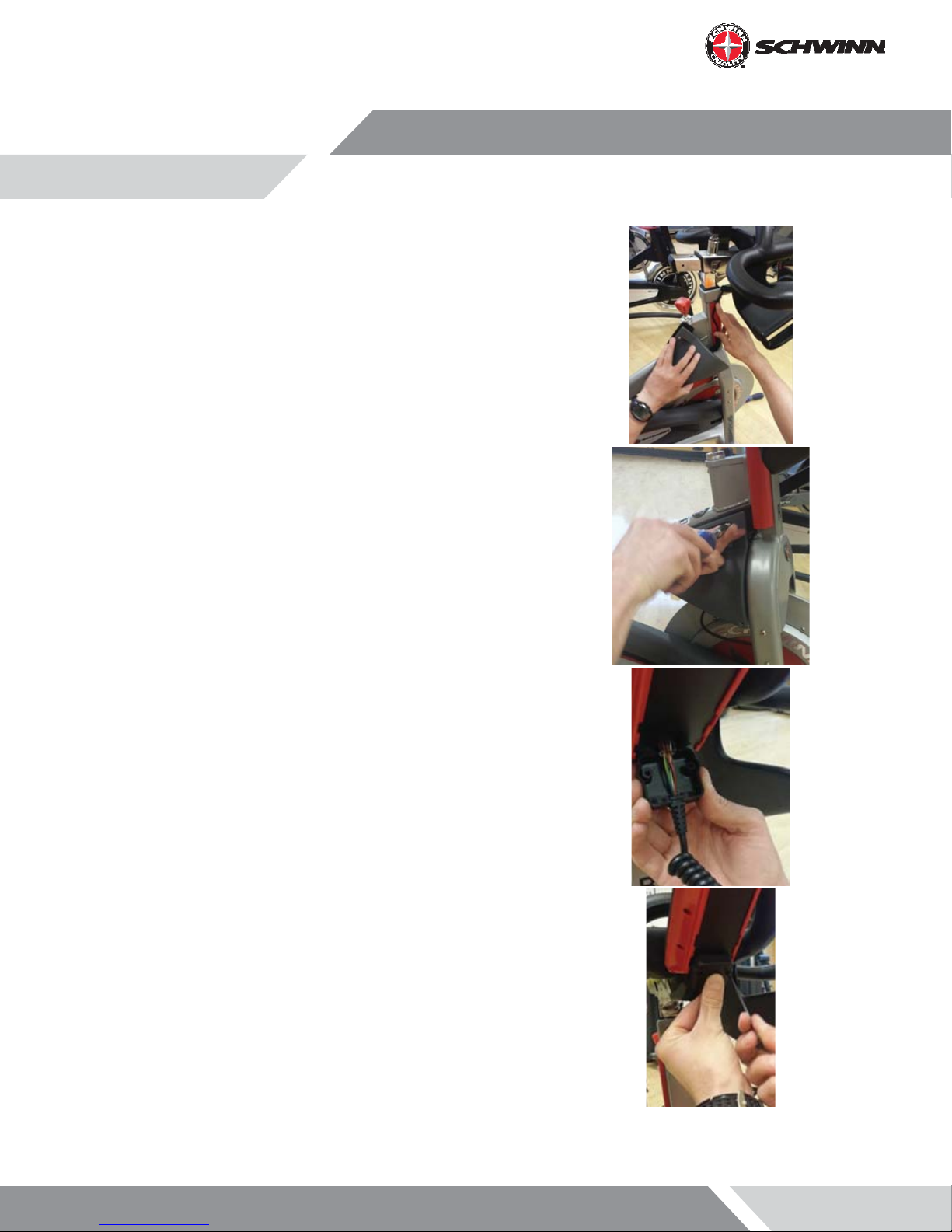
11. Re-mount the sweat guard
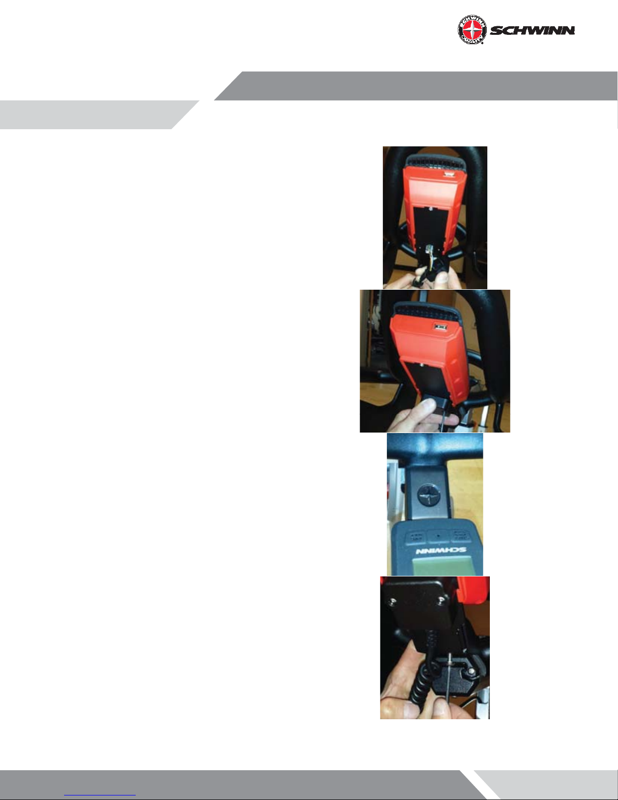
12. Plug the console cable RJ45 connector into the console then
slide the grommet of the cable into the slot on the connector
protective cap as shown
13. Attach the protective cap to the bracket using the two (2) M3
x 12mm socket head cap screws, and tighten with the 2.5mm
hex key
Page 16
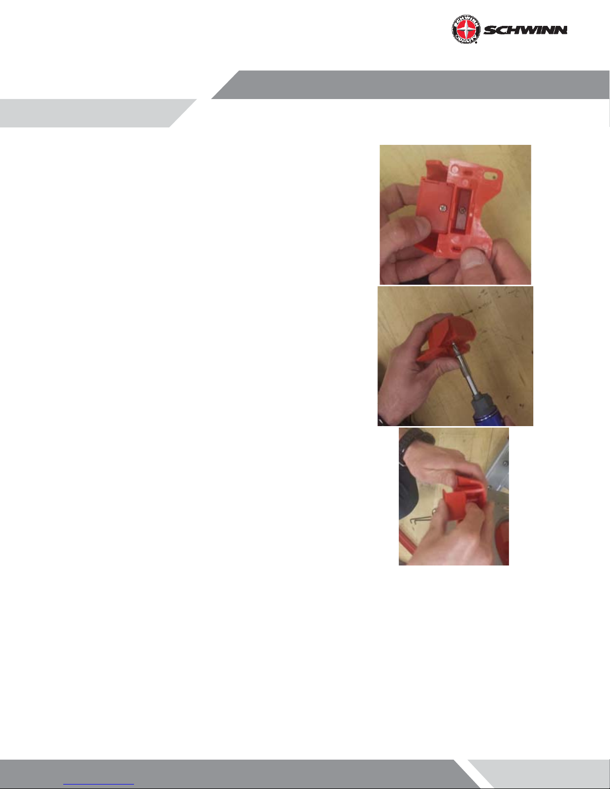
14. Attach the RPM sensor adapter to the RPM sensor using the M3
x 6mm Philips Pan Head Screw
15. Unscrew the M3 x 6mm Philips Pan Head screw holding the
RPM sensor cover on and remove it
Page 17
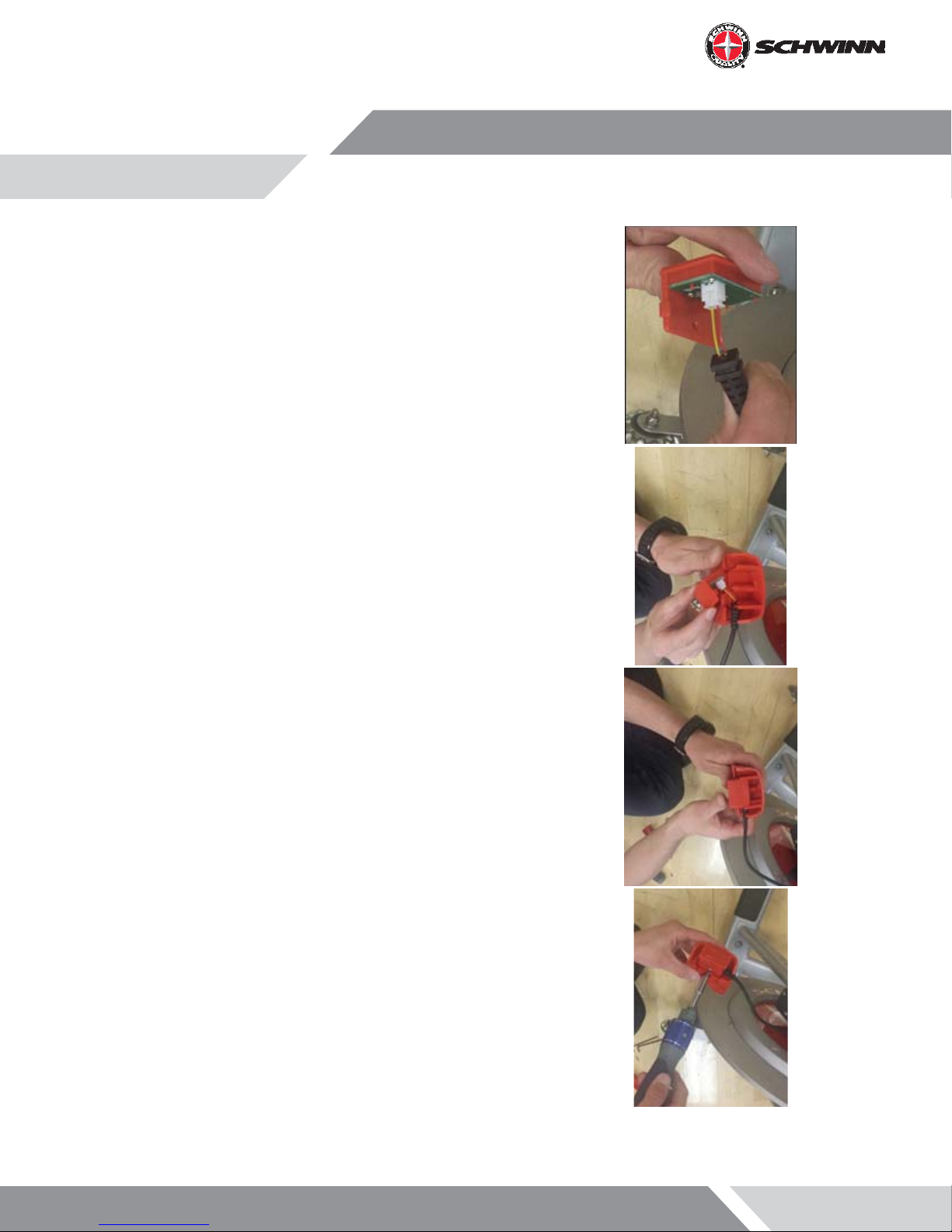
16. Plug the RPM sensor cable 2-pin connector into the RPM sensor
connector and slide the cable grommet into the slot in the RPM
sensor housing
17. Reinstall the RPM sensor cover into the housing, and reinstall
the M3 x 6mm Philips Pan Head screw
Page 18
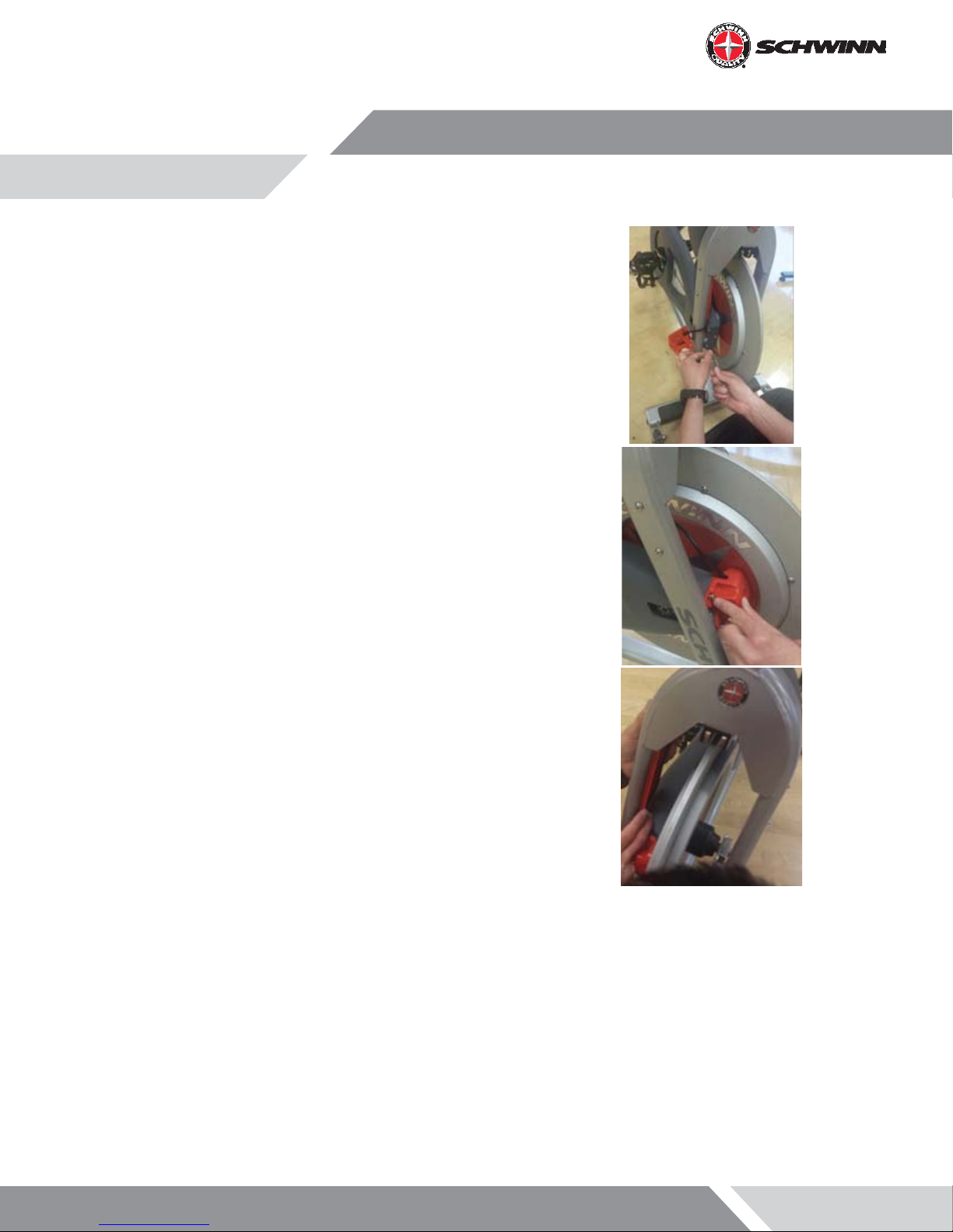
18. Remove the top and bottom screw from the front of the chain
guard
19. Position the RPM sensor as shown and reinstall the two chain
guard screws. The RPM sensor should be about 2 - 3mm away
from the ywheel, or about the width of a credit card. If the
RPM sensor is too close, it will rub against the sensor magnet
that is embedded in the ywheel. If the RPM sensor is too far
away, the sensor will intermittently pick up a signal from the
magnet or will not pick up any signal at all; this will cause an
erratic RPM display, or no RPM display
20. Prior to applying the lower conduit, clean the surface of the
inner right fork with isopropyl alcohol and allow to air dry. Peel
the non-stick strip o the plastic conduit base. Place it rmly
on the inside of the right hand fork. There should be about one
inch gap between chain guard/rpm sensor bracket and the
wire conduit
Page 19
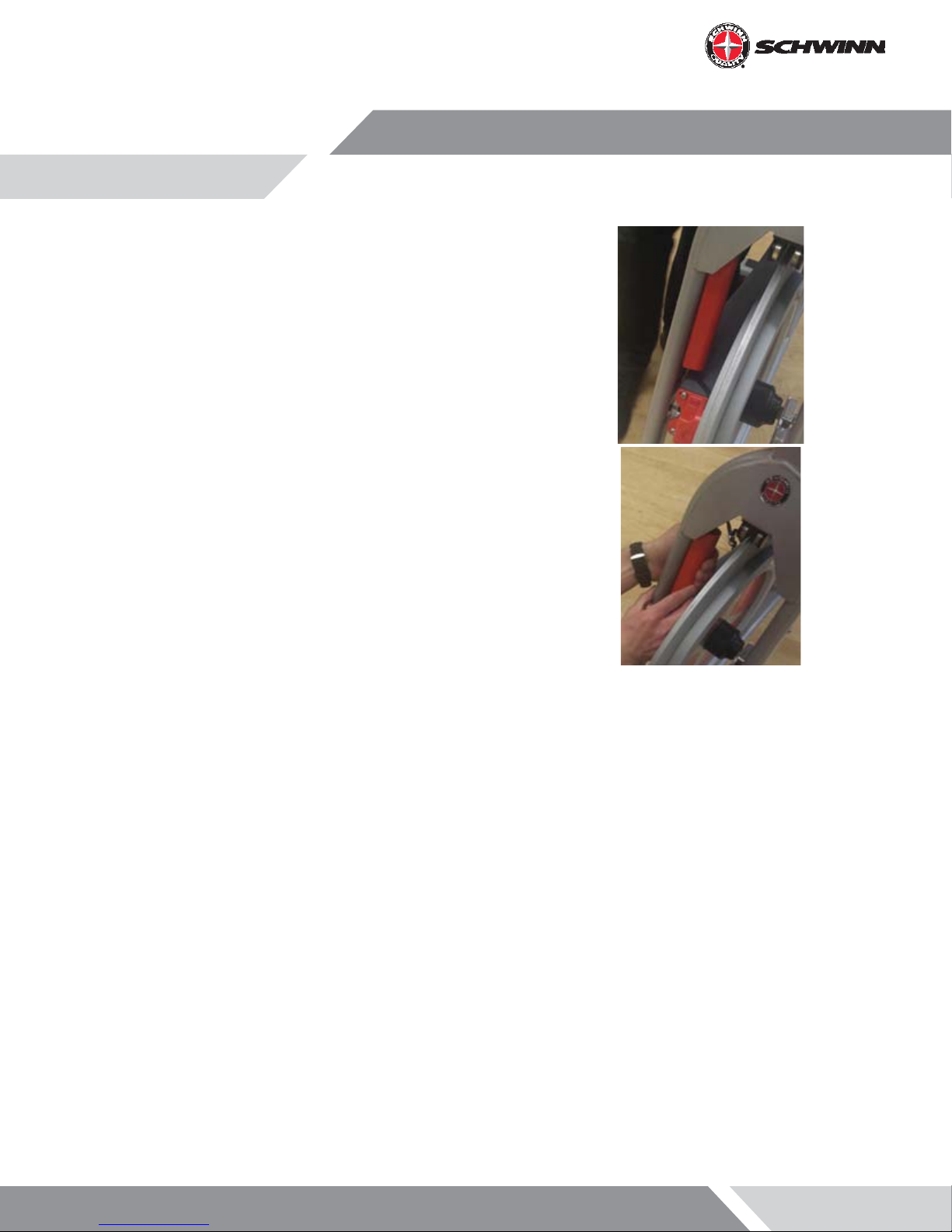
21. Route the wire inside the conduit and snap the conduit outer
cover on to the base
Page 20
AC Performance Plus™ and AC Performance Plus Carbon Blue™ Installation
NOTE: If installing the console with the optional power upgrade at the same time as the console, review the instructions in the section “Optional Power Upgrade Kit Installation on AC™ Performance Plus” before proceeding
with the steps in this section.
1. Insert batteries into console
2. Remove handlebars from bike and place on a sturdy working surface.
3. Grab the console-to-RPM cable and note which end has the 2-pin connector.
4. Insert the end of cable with the 2-pin connector
into the opening at the top of the handlebar
post. Feed the cable through, with one section
of coiled cable being inside the tube, and one
section of coiled cable being outside the tube.
The end of the cable should just be poking out of
the end of the tube
Page 21
5. Place the handlebar back on the bike.
6. Feed the end of the cable out of the end of the
head tube. Wear heavy-duty protective gloves
when pulling the end of the cable out of the
head tube as there may be sharp edges inside
the head tube
7. Mount the console bracket using the three (3) M4
x 10mm Philips Pan Head screws, and tighten the
screws
8. Slide the console onto the bracket. Insert the
M3 x 6mm pan head screw and tighten with the
screw driver
Page 22
9. Plug the console cable RJ45 connector into the
console then slide the grommet of the cable
into the slot on the connector protective cap as
shown
10. Attach the protective cap to the bracket using
the two (2) M3 x 12mm socket head cap screws,
and tighten with the 2.5mm hex key
11. Install the cosmetic cap using a M5 x 14mm BHCS
Page 23
12. Using a Philips screw driver, remove the sweat
guard (Do not use a power drill in removing and
re-installing). Route the cable through the sweat
guard
13. Unscrew the M3 x 6mm Philips Pan Head screw
holding the RPM sensor cover on and remove it
Page 24
 Loading...