

Page 1
Assembly
®
® ®
AD4
Schwinn
Schwinn Schwinn
Important
Important Important
• ••Readandunderstandallwarningsonthismachine.• ••CarefullyreadandunderstandtheAssemblyManual.• ••Keepbystandersandchildrenawayfromtheproductyouare
assemblingatalltimes.• ••Donotassembleequipmentinawetordamplocation.• ••Makesureassemblyisdoneinanappropriateworkspaceawayfromfoottrafficand
exposuretobystanders.• ••Somecomponentsofthemachinecanbeheavyorawkward.Useasecondpersonwhendoingtheassemblystepsinvolvingtheseparts.Donotdo
stepsthatinvolveheavyliftingorawkwardmovementsonyourown.• ••Donottrytochangethedesignorfunctionalityofthismachine.Thiscouldcompromisethesafetyand
canvoidthewarranty.• ••IfreplacementpartsarenecessaryuseonlygenuineSchwinn®replacementpartsandhardwaresuppliedbyNautilus.Failuretousegenuine
replacementpartscancausearisktousers,keepthemachinefromoperatingcorrectlyorvoidthewarranty.• ••Donotuseuntilthemachinehasbeenfullyassembledand
inspectedforcorrectperformanceinaccordancewiththeOwner’sManual.• ••ReadandunderstandthecompleteOwner’sManualsuppliedwiththismachinebeforefirstuse.
KeeptheOwner’ sManualforfuturereference.• ••Doallassemblystepsinthesequencegiven.Incorrectassemblycanleadtoinjury.
Nautilus,Inc.,(800)NAUTILUS/(800)628-8458,www.NautilusInc.com-CustomerService:NorthAmerica(800)605-3369,
[email protected]|Europe,MiddleEast&Africa490220320200,[email protected]|Germany&Austria+490220320200,Switzerland+41264607766,UnitedKingdom
+441908267345,AsiaPacific&LatinAmerica(360)859-5180,[email protected]|Patentinformation:ThisproductmaybecoveredbyUSandForeignPatentsandPatentsPending.See
Productformoreinformation.|PrintedinTaiwan|©2010Nautilus,Inc.,Allrightsreserved.™and®indicateatrademarkorregisteredtrademark.Nautilus,Inc.(www.nautilus.com)trademarksinclude
NAUTILUS®,BOWFLEX®,SCHWINN®andUNIVERSAL®andrespectivelogos.Othertrademarksarethepropertyoftheirrespectiveowners.
Safety
Safety Safety
Thisiconmeansapotentiallyhazardoussituationwhich,ifnotavoided,couldresultindeathorseriousinjury.Obeythefollowingwarnings:
Instructions
Instructions Instructions
Airdyne
AD4 AD4
Airdyne Airdyne
Assembly Assembly
Manual
Manual Manual
003–3240.021510.A
Before
Before Before
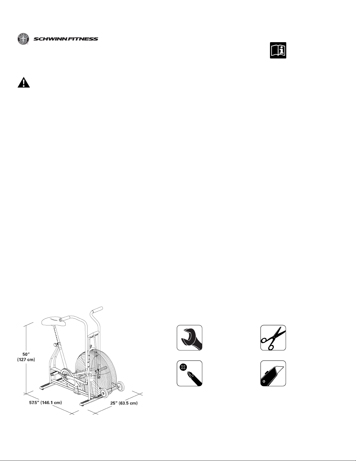
Selecttheareawhereyouaregoingtosetupandoperateyourmachine.Forsafeoperation,thelocationmustbeonahard,levelsurface.Allowaworkoutareaof
minimum64.4”x96.9”(163.6cmx246.1cm).
Followthesebasicpointswhenyouassembleyourmachine:
1.Readandunderstandthe“ImportantSafetyInstructions”beforeassembly.
2.Collectallthepiecesnecessaryforeachassemblystep.
3.Usingtherecommendedwrenches,turntheboltsandnutstotheright(clockwise)totighten,andtheleft(counterclockwise)toloosen,unlessinstructedotherwise.
4.Whenattaching2pieces,lightlyliftandlookthroughtheboltholestohelpinserttheboltthroughtheholes.
5.Theassemblyrequires2people.
Specifications
Specifications Specifications
Assembly
Assembly Assembly
and
ools
and and
T TTools ools
Not
Included
Not Not
Included Included
1/4”
5/16”
15mm
#2
(recommended)
(recommended)
1
1 1
Page 2
Parts
Parts Parts
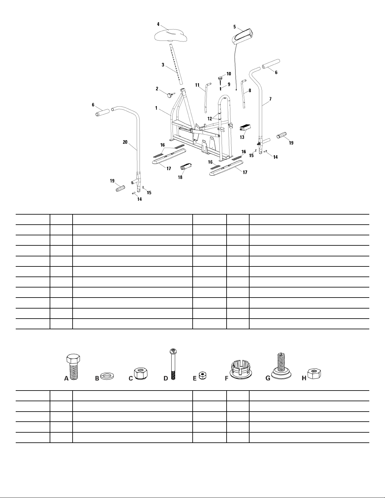
* **FanAssemblyremovedforclarity.
Hardware
Hardware Hardware
Item
Item Item
11
2
3
41
51
62
71
8
9
10
Qty
Qty Qty
1
1
1
1
1
Description
Description Description
FrameAssembly(includesFanAssembly)
LockingKnob(Seat)
SeatPost
Seat
Console
HandGrip
Arm,Left
ConsoleSupportTube,Left
Spring,LockingKnob
LockingKnob(Wheel)
Item
Item Item
111
122
13
14
15
16
17
18
192
20
Qty
Qty Qty
1
2
2
4
2
1
1
Description
Description Description
ConsoleSupportTube,Right
ConsoleCableStrap
Pedal,Left
ClevisPin
CotterPin
SkidResistancePad
Stabilizers
Pedal,Right
FootRestCover
Arm,Right
Item
Item Item
A
B
C
D
Description
Qty
Description Description
Qty Qty
4
CarriageBolt,5/16–24UNFx19L
4
LockWasher,5/16F
4
Nut,5/16
4
PhillipsHeadScrew,M5x0.8x50L
Item
Item Item
E
G
H
2
2 2
Qty
Qty Qty
4
2
4
4
Description
Description Description
Nut,M5Nylon
EndPlug
Leveler,3/8–16UNC
LevelerLockNut,3/8
Page 3
Assembly
Assembly Assembly
Attach
1. 1.1.Attach Attach
Attach
2. 2.2.Attach Attach
Levelers
Levelers Levelers
Stabilizers
Stabilizers Stabilizers
Stabilizers
to totoStabilizers Stabilizers
Frame
to totoFrame Frame
Assembly
Assembly Assembly
Note:
Note: Note:
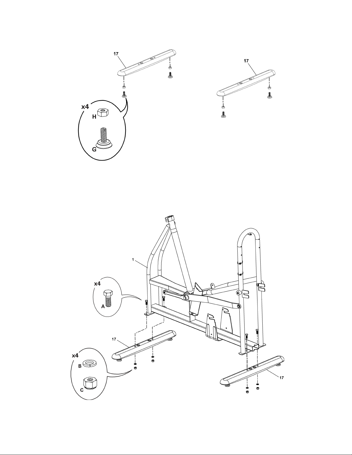
FanAssemblyremovedforclarity.
3
3 3
Page 4
Attach
Right
and
Left
3. 3.3.Attach Attach
Right Right
and and
Arms
Left Left
Arms Arms
Connect
4. 4.4.Connect Connect
Arms
Arms Arms
the
Lever
to totothe the
Arms
Lever Lever
Arms Arms
4
4 4
Page 5
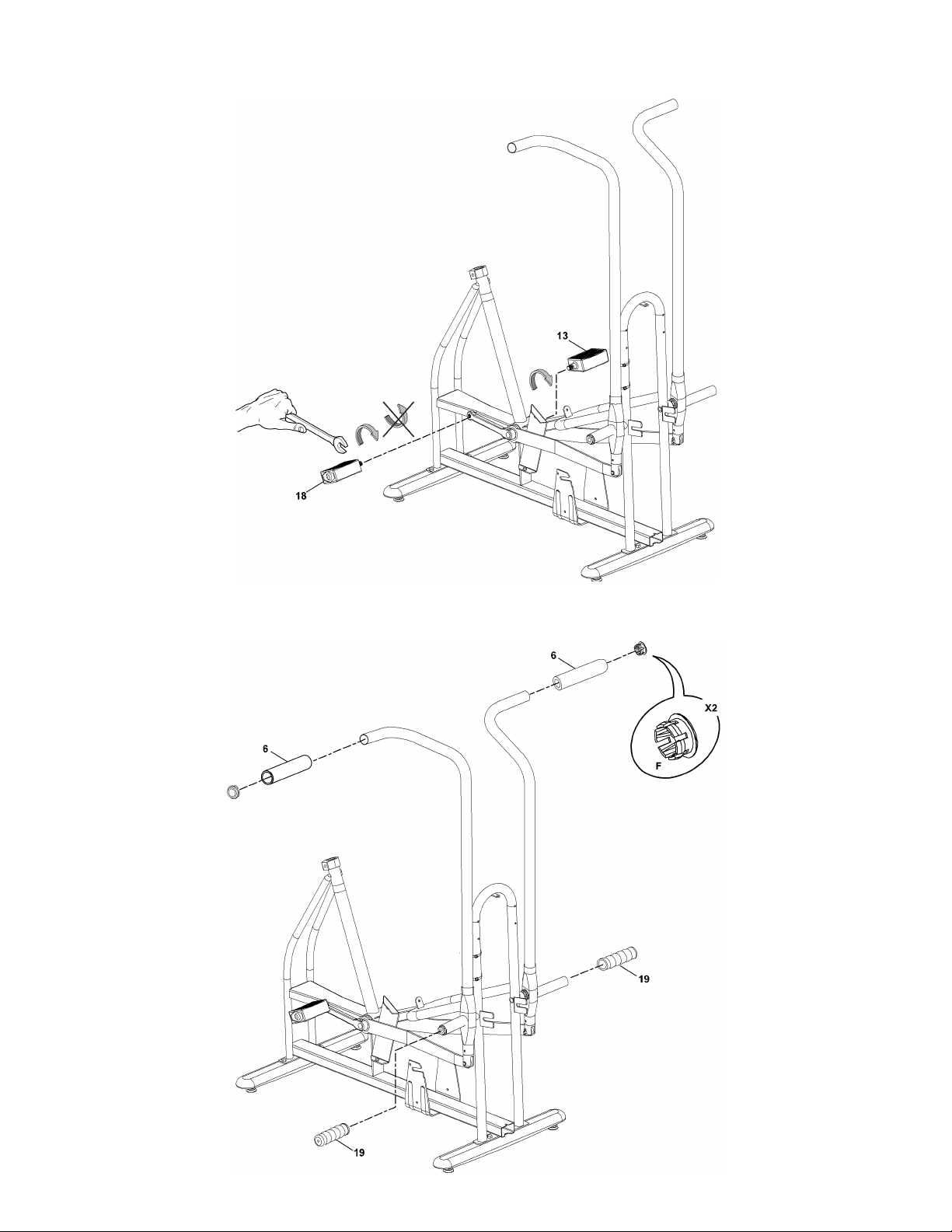
Attach
5. 5.5.Attach Attach
Pedals
Pedals Pedals
Note:
Note: Note:
BesuretoattachPedalsonthepropersideoftheBike.Orientationisbasedfromaseatedpositiononthebike.TheLeftPedalhasan
“L”,theRightPedalan“R”.
Attach
Foot
Rest
Covers
and
Hand
6. 6.6.Attach Attach
Foot Foot
Rest Rest
Covers Covers
and and
Grips
Hand Hand
Grips Grips
5
5 5
Page 6
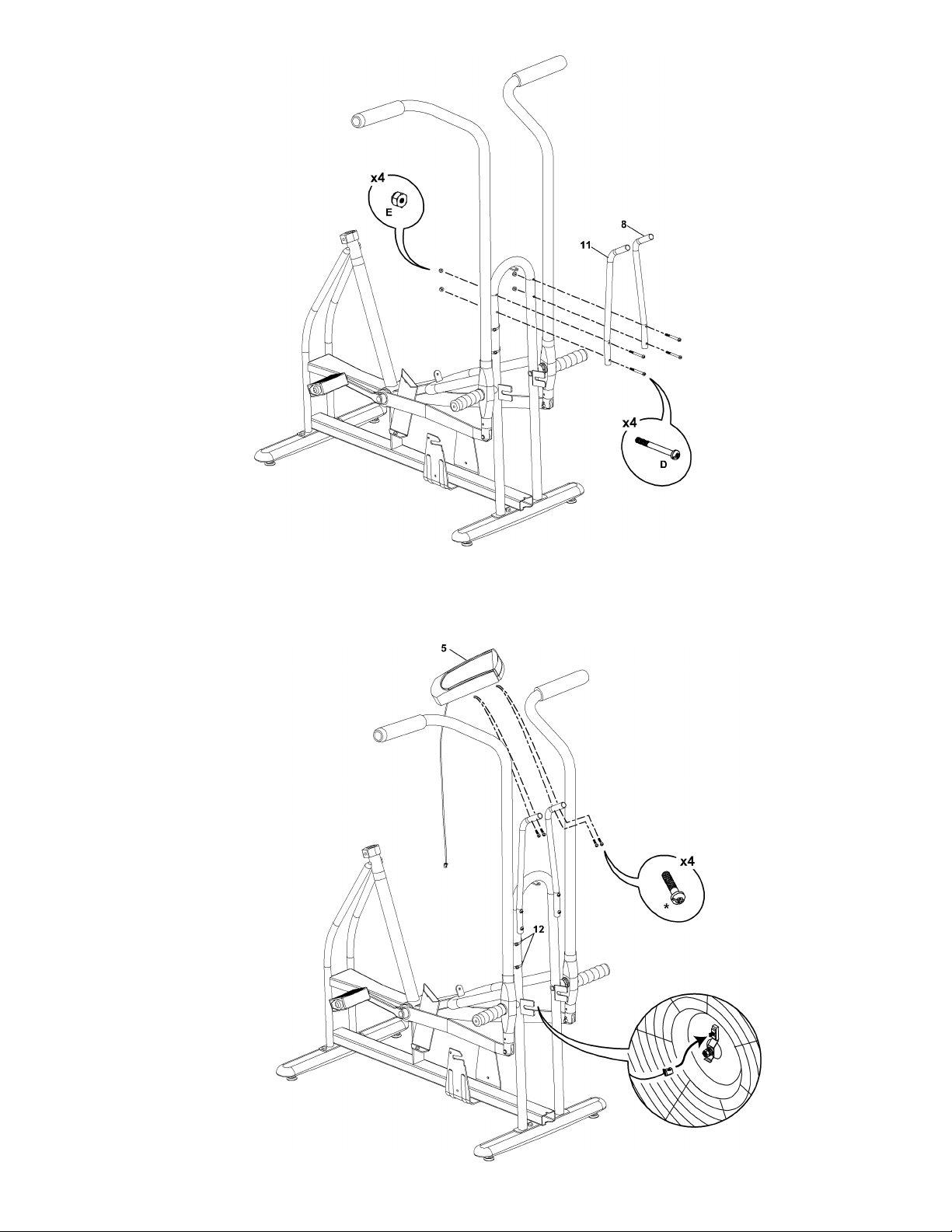
Attach
Right
and
Left
7. 7.7.Attach Attach
Right Right
and and
Console
Left Left
Console Console
Support
Support Support
ubes
T TTubes ubes
Connect
8. 8.8.Connect Connect
and
Attach
the
and and
Attach Attach
Note:
Note: Note:
Console
the the
Console Console
DonotcrimpConsoleCable.UseConsoleCableStraps(#12)tosecureCabletoConsoleSupportTube.ConnecttheConsoleCabletothe
fansensorontherightsideoftheFanAssembly.
* **Hardwareispre-installedandnotontheHardwareCard.
6
6 6
Page 7
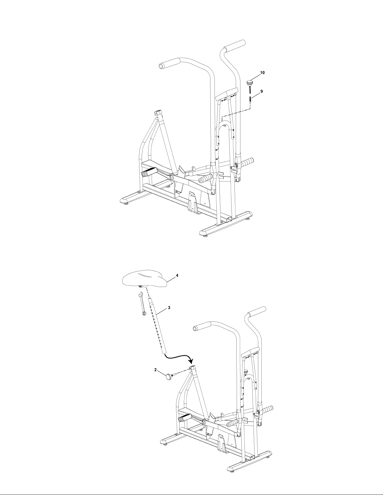
Attach
Wheel
9. 9.9.Attach Attach
Locking
Wheel Wheel
Locking Locking
Knob
and
Spring
Knob Knob
and and
Guide
Spring Spring
Guide Guide
10.
Attach
10. 10.
Seat
Attach Attach
Seat Seat
Seat
Post
and
Insert
into
Frame
to totoSeat Seat
Post Post
and and
Insert Insert
into into
Assembly
Frame Frame
Assembly Assembly
7
7 7
Page 8
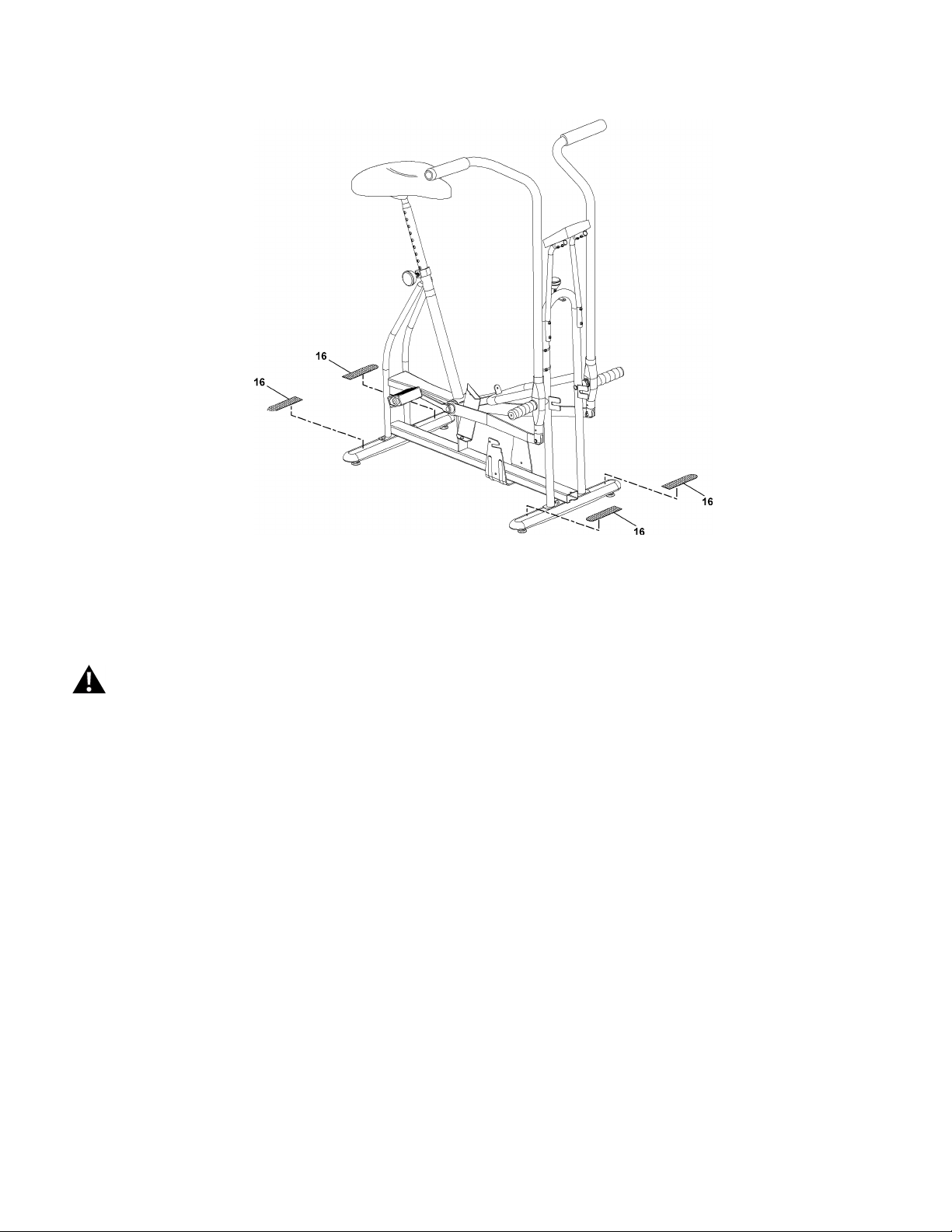
11.
Apply
Skid
11. 11.
Apply Apply
Resistance
Skid Skid
Resistance Resistance
Pads
Pads Pads
Final
Inspection
Final Final
Inspection Inspection
Inspectyourmachinetoensurethatallfastenersaretightandcomponentsareproperlyassembled.
DonotuseuntilthemachinehasbeenfullyassembledandinspectedforcorrectperformanceinaccordancewiththeOwner’sManual.
8
8 8
 Loading...