

Page 1
Core Health & Fitness
Schwinn®
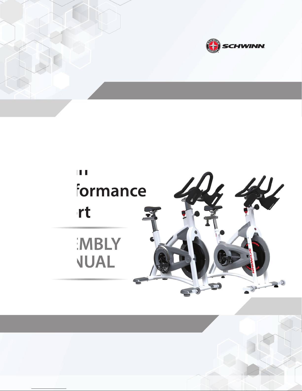
AC Performance
AC Sport
ASSEMBLY
MANUAL
Page 2
AC Performance
Required Tools:
• 5mm Allen Key
• 10mm Allen Key
• 17mm Open-ended Wrench
• 8mm Allen Socket
• Torque Wrench
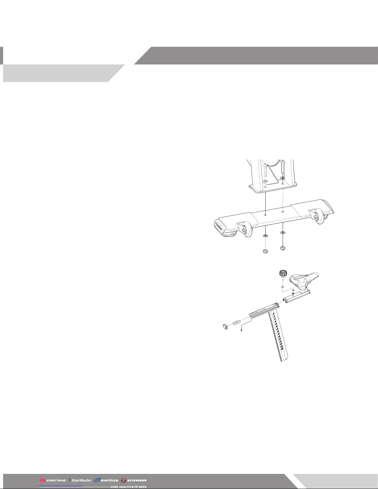
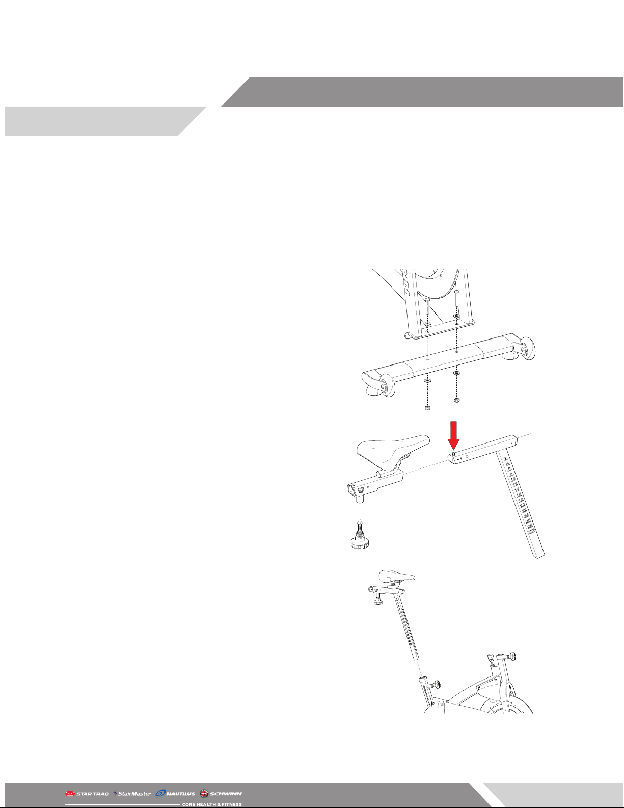
1. Install the front stabilizer using a 5mm allen key
and a 17mm open-ended wrench to secure two
(2) pieces each of the M10 x 50mm screws and
M10 nuts. Be sure to place one (1) piece of the
M10 washer between the nuts and the stabilizer
as well as the screws and the frame. Repeat this
step to attach the rear stabilizer to the frame.
2. Insert one (1) piece of the trapezoidal fore/aft
locking nut into the seat post slider then slide
the fore/aft seat slider onto the seat post. Insert
one (1) piece of the threaded collar locking nut
through the hole in the fore/aft seat slider and
into the trapezoidal fore/aft locking nut then
tighten with a 10mm allen key.
3. Slide one (1) piece each of the M8 washer and
M8 nylon washer onto the fore/aft adjustment
knob then tighten the fore/aft adjustment knob
into the threaded collar locking nut. Finally, insert
the end cap into the seat post and secure using
a phillips screwdriver and one (1) piece of M4 x
19mm screw.
Page 1
Page 3
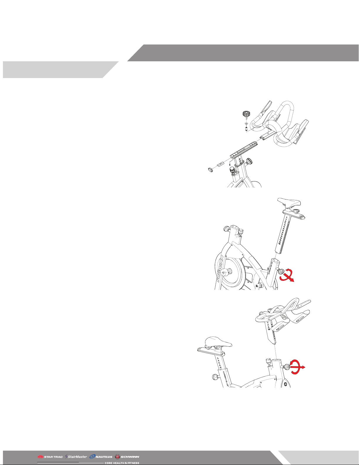
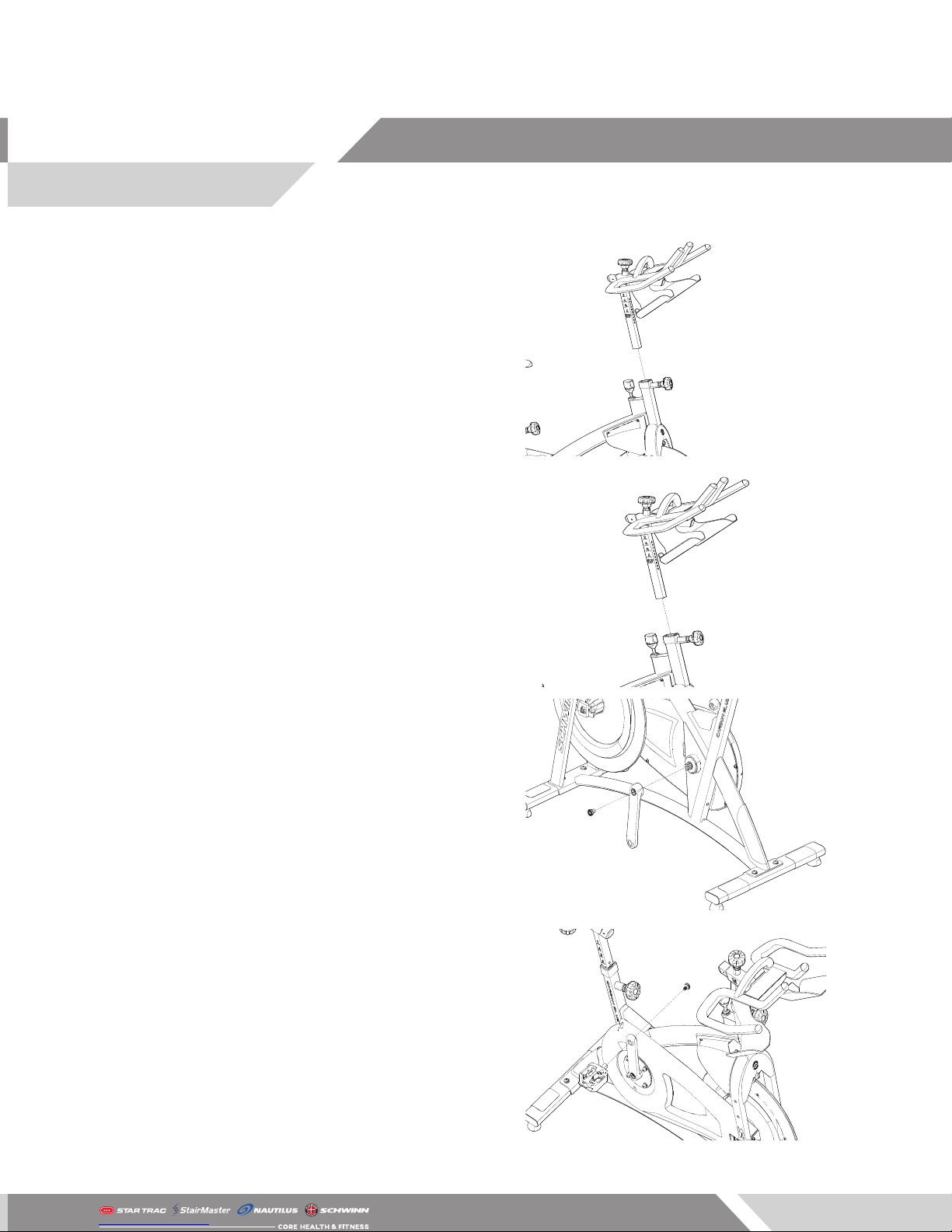
4. Insert one (1) piece of the trapezoidal fore/aft
locking nut into the handlebar post slider then
slide the fore/aft handlebar slider onto the handlebar post. Insert one (1) piece of the threaded
collar locking nut through the hole in the fore/aft
handlebar slider and into the trapezoidal fore/aft
locking nut then tighten with a 10mm allen key.
5. Slide one (1) piece each of the M8 washer and
M8 nylon washer onto the fore/aft adjustment
knob then tighten the fore/aft adjustment knob
into the threaded collar locking nut. Finally, insert
the end cap into the handlebar post and secure
using a phillips screwdriver and one (1) piece of
M4 x 19mm screw.
6. Slide the seat post assembly built in Step 2 into
the frame by loosening the height adjustment
pop pin, then pulling outwards on the pin while
sliding the seat post assembly into the frame.
7. Slide the handlebar post assembly built in Step
3 into the frame by loosening the height adjustment pop pin, then pulling outwards on the pin
while sliding the handlebar post assembly into
the frame.
Page 2
Page 4
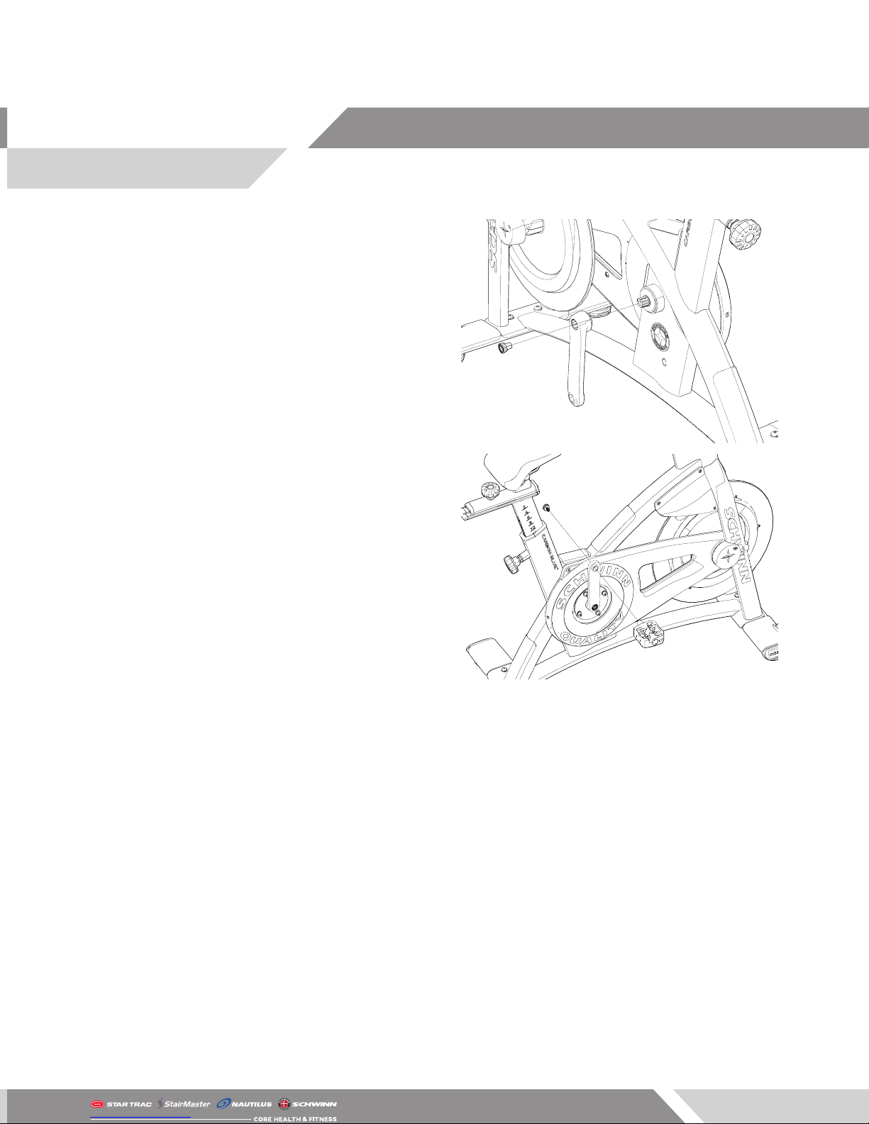
8. IF 4IIII POWER SENSOR IS BEING INSTALLED,
SKIP THIS STEP AND REFER TO INSTALL DOCUMENTATION FOR THE 4IIII CRANK ARM. Install
the left crank arm onto the left side of the bottom bracket ensuring that the right crank arm is
at the 12 o’clock position while the left crank arm
is at the 6 o’clock position. Finally, use a torque
wrench and a 8mm allen key socket to secure
one (1) piece of the crank bolt through the crank
arm and into the bottom bracket, torquing to 3337 ft-lbs (48 Nm)
9. Install the pedal into the crank arm then use a
torque wrench and a 8mm allen socket to secure
one (1) piece of the crank bolt from the other
side of the pedal, torquing to 33-37 ft-lbs (48
Nm). Repeat this step for the rider left side pedal.
CAUTION: The pedal MUST be torqued to the above
speci cations otherwise a failure of the pedal may
occur.
Page 3
Page 5
AC Sport
Required Tools:
• 5mm Allen Key
• 13mm Open-ended Wrench
• 12mm Open-ended Wrench
• 8mm Allen Socket
• Torque Wrench
1. Install the front stabilizer using a 5mm allen key
and a 13mm open-ended wrench to secure two
(2) pieces each of the M8 x 45mm screws and
M8 nuts. Be sure to place one (1) piece of the M8
washer between the nuts and the stabilizer as
well as the screws and the frame. Repeat this step
to attach the rear stabilizer to the frame.
2. Tighten the fore/aft adjustment pop pin into
the seat post slider using a 21mm open-ended
wrench then depress the button on the seat post
while sliding the seat slider onto the seat post.
3. Loosen the seat post height adjustment pop pin
on the bike’s frame by turning the knob counter-clockwise, then pull outwards on the pin while
sliding the seat post assembly into the frame.
Page 4
Page 6
4. First, tighten the fore/aft adjustment pop pin into
the handle bar post using a 21mm open-ended wrench then loosen the pop pin by turning
counter-clockwise. Pull outwards on the pin
while sliding the handlebars into the post then
thread the M5 x 16mm screw into the underside
of the handlebars, tightening with a 4mm allen
key to secure.
5. Loosen the handlebar post height adjustment
pop pin on the bike’s frame by turning the knob
counter-clockwise, then pull outwards on the pin
while sliding the handlebar post assembly into
the frame.
6. IF 4IIII POWER SENSOR IS BEING INSTALLED,
SKIP THIS STEP AND REFER TO INSTALL DOCUMENTATION FOR THE 4IIII CRANK ARM. Install
the left crank arm onto the left side of the bottom bracket ensuring that the right crank arm is
at the 12 o’clock position while the left crank arm
is at the 6 o’clock position. Finally, use a torque
wrench and a 8mm allen key socket to secure
one (1) piece of the crank bolt through the crank
arm and into the bottom bracket, torquing to 3337 ft-lbs (48 Nm)
7. Install the pedal into the crank arm then use a
torque wrench and a 8mm allen socket to secure
one (1) piece of the crank bolt from the other
side of the pedal, torquing to 33-37 ft-lbs (48
Nm).Repeat this step for the rider left side pedal.
CAUTION: The pedal MUST be torqued to the above
speci cations otherwise a failure of the pedal may
occur.
Page 5
Page 7
© 2018 CORE HEALTH & FITNESS, LLC PART NUMBER 620-8622, REV B
 Loading...