

Page 1
Translation of the original manual
Assembly and Operating Manual
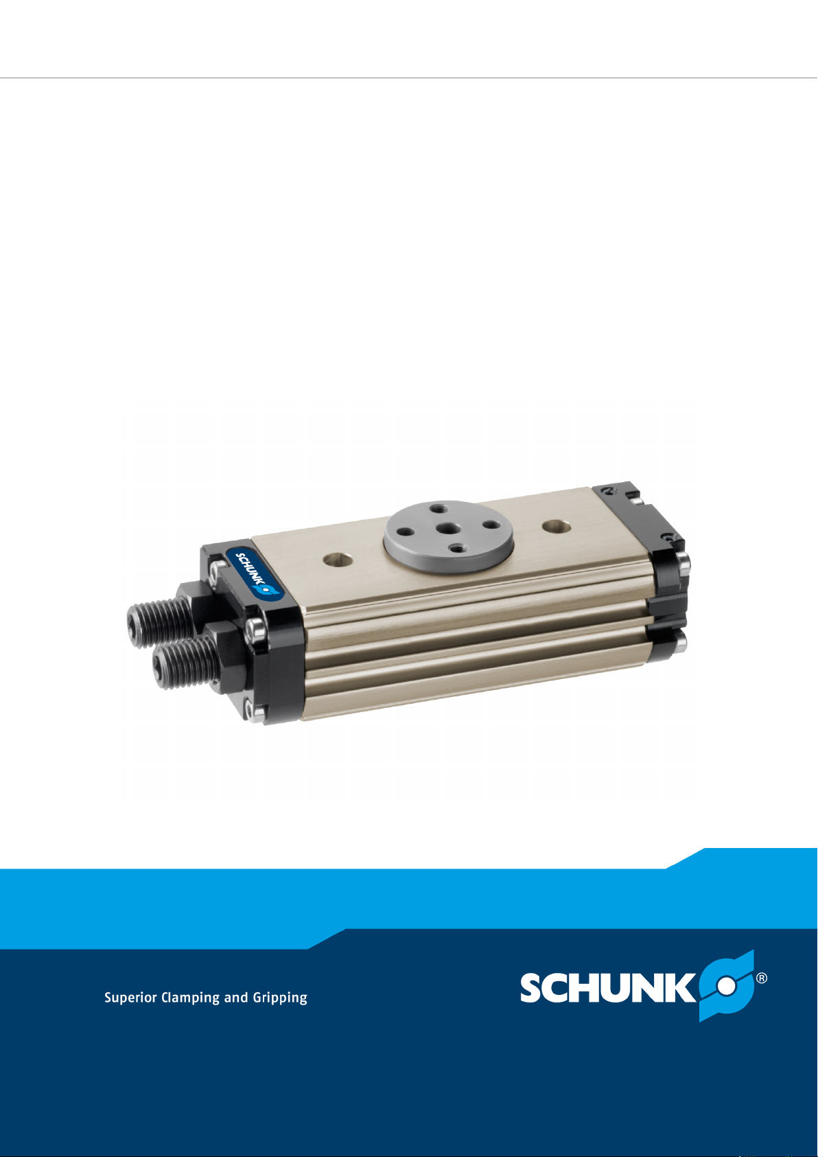
SRU
Pneumatic Rotary Unit
Page 2

Imprint
Imprint
Copyright:
This manual is protected by copyright. The author is SCHUNK GmbH & Co. KG. All rights
reserved. Any reproduction, processing, distribution (making available to third parties),
translation or other usage - even excerpts - of the manual is especially prohibited and
requires our written approval.
Technical changes:
We reserve the right to make alterations for the purpose of technical improvement.
Document number: 389439
Version: 10.00|03/05/2019|en
© SCHUNK GmbH & Co. KG
All rights reserved.
Dear Customer,
thank you for trusting our products and our family-owned company, the leading
technology supplier of robots and production machines.
Our team is always available to answer any questions on this product and other solutions.
Ask us questions and challenge us. We will find a solution!
Best regards,
Your SCHUNK team
SCHUNK GmbH & Co. KG
Spann- und Greiftechnik
Bahnhofstr. 106 – 134
D-74348 Lauffen/Neckar
Tel. +49-7133-103-0
Fax +49-7133-103-2399
[email protected]
schunk.com
2
10.00 | SRU | Assembly and Operating Manual | en | 389439
Page 3

Table of contents
Table of contents
1 General.................................................................................................................... 5
1.1 About this manual ................................................................................................5
1.1.1 Presentation of Warning Labels ...............................................................5
1.1.2 Applicable documents ..............................................................................6
1.1.3 Sizes ..........................................................................................................6
1.1.4 Variants..................................................................................................... 6
1.2 Warranty .............................................................................................................. 6
1.3 Scope of delivery ..................................................................................................7
1.3.1 Accessory pack..........................................................................................7
1.4 Accessories ........................................................................................................... 8
1.4.1 Seal kit ......................................................................................................8
2 Basic safety notes ................................................................................................... 9
2.1 Intended use......................................................................................................... 9
2.2 Not intended use.................................................................................................. 9
2.3 Constructional changes ........................................................................................9
2.4 Spare parts ......................................................................................................... 10
2.5 Environmental and operating conditions ...........................................................10
2.6 Personnel qualification....................................................................................... 10
2.7 Personal protective equipment.......................................................................... 12
2.8 Notes on safe operation ..................................................................................... 12
2.9 Transport ............................................................................................................ 13
2.10 Malfunctions....................................................................................................... 13
2.11 Disposal .............................................................................................................. 14
2.12 Fundamental dangers......................................................................................... 14
2.12.1 Protection during handling and assembly ..............................................14
2.12.2 Protection during commissioning and operation ...................................15
2.12.3 Protection against dangerous movements.............................................15
2.12.4 Protection against electric shock............................................................16
2.13 Notes on particular risks..................................................................................... 17
3 Technical data.........................................................................................................19
3.1 Type key.............................................................................................................. 19
3.2 Basic data ........................................................................................................... 20
4 Design and description............................................................................................21
4.1 Design ................................................................................................................. 21
4.2 Description ......................................................................................................... 21
5 Assembly ................................................................................................................22
5.1 Assembling and connecting................................................................................ 22
5.2 Connections........................................................................................................ 24
5.2.1 Mechanical connection...........................................................................24
10.00 | SRU | Assembly and Operating Manual | en | 389439
3
Page 4

Table of contents
5.2.2 Pneumatic connection............................................................................26
5.3 Settings............................................................................................................... 27
5.3.1 Adjustment of the end positions ............................................................27
5.3.2 Adjustment of the central position (Variant M) .....................................28
5.4 Installing the sensors.......................................................................................... 29
5.4.1 Overview of sensors ...............................................................................29
5.4.2 Mounting MMS 22 magnetic switch.......................................................30
5.4.3 Mounting MMS 22-PI1 programmable magnetic switch........................31
6 Commissioning .......................................................................................................32
6.1 Setting the speed................................................................................................ 32
6.2 Adjustment of the shock absorber stroke ..........................................................34
6.2.1 Shock absorber stroke (variant H) ..........................................................35
6.2.2 Shock absorber stroke (variant S)...........................................................36
7 Troubleshooting .....................................................................................................37
7.1 Product does not move ......................................................................................37
7.2 Product does not travel through the entire stroke ............................................37
7.3 Product rotates jerkily ........................................................................................38
7.4 Torque diminishes? ............................................................................................ 38
8 Maintenance ..........................................................................................................39
8.1 Notes .................................................................................................................. 39
8.2 Maintenance interval ......................................................................................... 39
8.3 Lubricants/Lubrication points (basic lubrication) ..............................................40
8.4 Disassembly and assembly .................................................................................40
8.4.1 Dismantle product ..................................................................................40
8.4.2 Notes for assembly .................................................................................41
8.4.3 Tightening torque for screws..................................................................41
8.4.4 Assembly drawing...................................................................................42
9 Translation of original declaration of incorporation ................................................45
10 Annex to Declaration of Incorporation....................................................................46
4
10.00 | SRU | Assembly and Operating Manual | en | 389439
Page 5
1 General
1.1 About this manual
This manual contains important information for a safe and
appropriate use of the product.
This manual is an integral part of the product and must be kept
accessible for the personnel at all times.
Before starting work, the personnel must have read and
understood this operating manual. Prerequisite for safe working is
the observance of all safety instructions in this manual.
Illustrations in this manual are provided for basic understanding
and may differ from the actual product design.
In addition to these instructions, the documents listed under
Applicable documents [}6] are applicable.
1.1.1 Presentation of Warning Labels
General
To make risks clear, the following signal words and symbols are
used for safety notes.
DANGER
Danger for persons!
Non-observance will inevitably cause irreversible injury or death.
WARNING
Dangers for persons!
Non-observance can lead to irreversible injury and even death.
CAUTION
Dangers for persons!
Non-observance can cause minor injuries.
NOTICE
Material damage!
Information about avoiding material damage.
10.00 | SRU | Assembly and Operating Manual | en | 389439
5
Page 6

General
1.1.2 Applicable documents
• General terms of business*
• Catalog data sheet of the purchased product *
• Assembly and operating manuals of the accessories *
The documents marked with an asterisk (*) can be downloaded on
our homepage schunk.com
1.1.3 Sizes
This operating manual applies to the following sizes:
• SRU 8
• SRU 10
• SRU 12
• SRU 14
1.1.4 Variants
This operating manual applies to the following variations:
• SRU with elastomer dampening (S)
• SRU with hydraulic dampening (H)
• SRU without dampening (W)
• SRU With pneumatic center positioning (M)
• SRU With fluid feed-through
• SRU explosion-protected version (Ex)
1.2 Warranty
If the product is used as intended, the warranty is valid for 24
months from the ex-works delivery date under the following
conditions:
• Observe the specified maintenance and lubrication intervals
• Observe the ambient conditions and operating conditions
Parts touching the workpiece and wear parts are not included in
the warranty.
6
10.00 | SRU | Assembly and Operating Manual | en | 389439
Page 7

1.3 Scope of delivery
The scope of delivery includes
• Pneumatic Rotary Unit SRU in the version ordered
• Assembly and Operating Manual
• Accessory pack
1.3.1 Accessory pack
Content of the accessory pack:
• 2 x centering sleeves for mounting
• 2 x O-rings for hose-free direct connection
• 2 x locking screws for hose connections
• 2 x cylinder pin
ID.-No. of the accessory pack
Accessory pack for Variants ID number
General
W/H/S 1004955
SRU 8
SRU 10
W/H/S-2 1004956
W/H/S-M 1004957
W/H/S-M-2 1004958
SRU 12 5524552
W/H/S 1004959
SRU 12
SRU 14
W/H/S-4 1004960
W/H/S-M 1004961
W/H/S-M-4 1004962
10.00 | SRU | Assembly and Operating Manual | en | 389439
7
Page 8

General
1.4 Accessories
A wide range of accessories are available for this product
For information regarding which accessory articles can be used
with the corresponding product variants, see catalog data sheet.
1.4.1 Seal kit
ID.-No. of the seal kit
Seal kit for Variants ID number
W/H/S 5517914
SRU 8
SRU 10
W/H/S-M 5517915
W/H/S-2/4 5517916
W/H/S-2/4 5517917
W/H/S 5517918
SRU 12
W/H/S-M 5517919
W/H/S-2/4 5517920
W/H/S-2/4 5517921
W/H/S 5517922
SRU 12
SRU 14
W/H/S-M 5517923
W/H/S-2/4 5517924
W/H/S-2/4 5517925
Contents of the sealing kit, Assembly drawing [}42].
8
10.00 | SRU | Assembly and Operating Manual | en | 389439
Page 9

Basic safety notes
2 Basic safety notes
2.1 Intended use
The product may only be used for swiveling permissible
attachment parts or workpieces.
• The product may only be used within the scope of its technical
data, Technical data [}19].
• When implementing and operating components in safetyrelated parts of the control systems, the basic safety principles
in accordance with DIN EN ISO 13849-2 apply. The proven safety
principles in accordance with DIN EN ISO 13849-2 also apply to
categories 1, 2, 3 and 4.
• The product is intended for installation in a machine/system.
The applicable guidelines must be observed and complied with.
• The product is intended for industrial and industry-oriented use.
• Appropriate use of the product includes compliance with all
instructions in this manual.
2.2 Not intended use
Inappropriate use includes using the product as a cutting tool or
drilling tool, for example.
• Any utilization that exceeds or differs from the appropriate use
is regarded as misuse.
2.3 Constructional changes
Implementation of structural changes
By conversions, changes, and reworking, e.g. additional threads,
holes, or safety devices can impair the functioning or safety of the
product or damage it.
• Structural changes should only be made with the written
approval of SCHUNK.
10.00 | SRU | Assembly and Operating Manual | en | 389439
9
Page 10

Basic safety notes
2.4 Spare parts
Use of unauthorized spare parts
Using unauthorized spare parts can endanger personnel and
damage the product or cause it to malfunction.
• Use only original spare parts or spares authorized by SCHUNK.
2.5 Environmental and operating conditions
Required ambient conditions and operating conditions
Incorrect ambient and operating conditions can make the product
unsafe, leading to the risk of serious injuries, considerable material
damage and/or a significant reduction to the product's life span.
See also Basic data [}20].
2.6 Personnel qualification
Inadequate qualifications of the personnel
If the personnel working with the product is not sufficiently
qualified, the result may be serious injuries and significant
property damage.
• All work may only be performed by qualified personnel.
• Before working with the product, the personnel must have read
and understood the complete assembly and operating manual.
• Observe the national safety regulations and rules and general
safety instructions.
10
10.00 | SRU | Assembly and Operating Manual | en | 389439
Page 11

Basic safety notes
The following personal qualifications are necessary for the various
activities related to the product:
Trained electrician
Qualified personnel
Instructed person
Service personnel of
the manufacturer
Due to their technical training, knowledge and experience, trained
electricians are able to work on electrical systems, recognize and
avoid possible dangers and know the relevant standards and
regulations.
Due to its technical training, knowledge and experience, qualified
personnel is able to perform the delegated tasks, recognize and
avoid possible dangers and knows the relevant standards and
regulations.
Instructed persons were instructed by the operator about the
delegated tasks and possible dangers due to improper behaviour.
Due to its technical training, knowledge and experience, service
personnel of the manufacturer is able to perform the delegated
tasks and to recognize and avoid possible dangers.
10.00 | SRU | Assembly and Operating Manual | en | 389439
11
Page 12

Basic safety notes
2.7 Personal protective equipment
Use of personal protective equipment
Personal protective equipment serves to protect staff against
danger which may interfere with their health or safety at work.
• When working on and with the product, observe the
occupational health and safety regulations and wear the
required personal protective equipment.
• Observe the valid safety and accident prevention regulations.
• Wear protective gloves to guard against sharp edges and
corners or rough surfaces.
• Wear heat-resistant protective gloves when handling hot
surfaces.
• Wear protective gloves and safety goggles when handling
hazardous substances.
• Wear close-fitting protective clothing and also wear long hair in
a hairnet when dealing with moving components.
2.8 Notes on safe operation
Incorrect handling of the personnel
Incorrect handling and assembly may impair the product's safety
and cause serious injuries and considerable material damage.
• Avoid any manner of working that may interfere with the
function and operational safety of the product.
• Use the product as intended.
• Observe the safety notes and assembly instructions.
• Do not expose the product to any corrosive media. This does
not apply to products that are designed for special
environments.
• Eliminate any malfunction immediately.
• Observe the care and maintenance instructions.
• Observe the current safety, accident prevention and
environmental protection regulations regarding the product's
application field.
12
10.00 | SRU | Assembly and Operating Manual | en | 389439
Page 13

2.9 Transport
Handling during transport
Incorrect handling during transport may impair the product's
safety and cause serious injuries and considerable material
damage.
• When handling heavy weights, use lifting equipment to lift the
product and transport it by appropriate means.
• Secure the product against falling during transportation and
handling.
• Stand clear of suspended loads.
2.10 Malfunctions
Behavior in case of malfunctions
• Immediately remove the product from operation and report the
malfunction to the responsible departments/persons.
• Order appropriately trained personnel to rectify the
malfunction.
Basic safety notes
• Do not recommission the product until the malfunction has
been rectified.
• Test the product after a malfunction to establish whether it still
functions properly and no increased risks have arisen.
10.00 | SRU | Assembly and Operating Manual | en | 389439
13
Page 14

Basic safety notes
2.11 Disposal
Handling of disposal
The incorrect handling of disposal may impair the product's safety
and cause serious injuries as well as considerable material and
environmental harm.
• Follow local regulations on dispatching product components for
recycling or proper disposal.
2.12 Fundamental dangers
General
• Observe safety distances.
• Never deactivate safety devices.
• Before commissioning the product, take appropriate protective
measures to secure the danger zone.
• Disconnect power sources before installation, modification,
maintenance, or calibration. Ensure that no residual energy
remains in the system.
• If the energy supply is connected, do not move any parts by
hand.
• Do not reach into the open mechanism or movement area of
the product during operation.
2.12.1 Protection during handling and assembly
Incorrect handling and assembly
Incorrect handling and assembly may impair the product's safety
and cause serious injuries and considerable material damage.
• Have all work carried out by appropriately qualified personnel.
• For all work, secure the product against accidental operation.
• Observe the relevant accident prevention rules.
• Use suitable assembly and transport equipment and take
precautions to prevent jamming and crushing.
Incorrect lifting of loads
Falling loads may cause serious injuries and even death.
• Stand clear of suspended loads and do not step into their
swiveling range.
• Never move loads without supervision.
• Do not leave suspended loads unattended.
14
10.00 | SRU | Assembly and Operating Manual | en | 389439
Page 15

2.12.2 Protection during commissioning and operation
Falling or violently ejected components
Falling and violently ejected components can cause serious injuries
and even death.
• Take appropriate protective measures to secure the danger
zone.
• Never step into the danger zone during operation.
2.12.3 Protection against dangerous movements
Unexpected movements
Residual energy in the system may cause serious injuries while
working with the product.
• Switch off the energy supply, ensure that no residual energy
remains and secure against inadvertent reactivation.
• Never rely solely on the response of the monitoring function to
avert danger. Until the installed monitors become effective, it
must be assumed that the drive movement is faulty, with its
action being dependent on the control unit and the current
operating condition of the drive. Perform maintenance work,
modifications, and attachments outside the danger zone
defined by the movement range.
Basic safety notes
• To avoid accidents and/or material damage, human access to
the movement range of the machine must be restricted. Limit/
prevent accidental access for people in this area due through
technical safety measures. The protective cover and protective
fence must be rigid enough to withstand the maximum possible
movement energy. EMERGENCY STOP switches must be easily
and quickly accessible. Before starting up the machine or
automated system, check that the EMERGENCY STOP system is
working. Prevent operation of the machine if this protective
equipment does not function correctly.
10.00 | SRU | Assembly and Operating Manual | en | 389439
15
Page 16

Basic safety notes
2.12.4 Protection against electric shock
Possible electrostatic energy
Components or assembly groups may become electrostatically
charged. When the electrostatic charge is touched, the discharge
may trigger a shock reaction leading to injuries.
• The operator must ensure that all components and assembly
groups are included in the local potential equalisation in
accordance with the applicable regulations.
• While paying attention to the actual conditions of the working
environment, the potential equalisation must be implemented
by a specialist electrician according to the applicable
regulations.
• The effectiveness of the potential equalisation must be verified
by executing regular safety measurements.
16
10.00 | SRU | Assembly and Operating Manual | en | 389439
Page 17
2.13 Notes on particular risks
DANGER
Risk of fatal injury from suspended loads!
Falling loads can cause serious injuries and even death.
• Stand clear of suspended loads and do not step within their
swiveling range.
• Never move loads without supervision.
• Do not leave suspended loads unattended.
• Wear suitable protective equipment.
WARNING
Risk of injury from objects falling and being ejected!
Falling and ejected objects during operation can lead to serious
injury or death.
Basic safety notes
• Take appropriate protective measures to secure the danger
zone.
WARNING
Risk of injury due to unexpected movements!
If the power supply is switched on or residual energy remains in
the system, components can move unexpectedly and cause
serious injuries.
• Before starting any work on the product: Switch off the power
supply and secure against restarting.
• Make sure, that no residual energy remains in the system.
WARNING
Risk of injury from sharp edges and corners!
Sharp edges and corners can cause cuts.
• Use suitable protective equipment.
WARNING
Risk of burns through contact with hot surfaces!
The product can heat up considerably during operation. Touching
hot surfaces can cause burns.
• Do not touch hot surfaces.
• Let them cool down before working on the product.
• Wear appropriate safety equipment.
10.00 | SRU | Assembly and Operating Manual | en | 389439
17
Page 18

Basic safety notes
WARNING
Risk of injury from parts coming loose!
If the shock absorbers are faulty, the product can become
damaged. Parts coming loose in this way can lead to injuries.
• Regularly check the components for wear and damage.
WARNING
Risk of injury if the condition or behavior of the product is
undefined!
Cutting off the compressed air supply in an uncontrolled manner
could lead to undefined states and behavior. This may cause
personal injury or material damage.
• The operator must define suitable emergency stop and
restarting strategies.
✓ Emergency stop strategies: e.g. by means of controlled shut
down
✓ Restarting strategies: e.g. using pressure build-up valves or
suitable valve switching sequences
18
10.00 | SRU | Assembly and Operating Manual | en | 389439
Page 19
3 Technical data
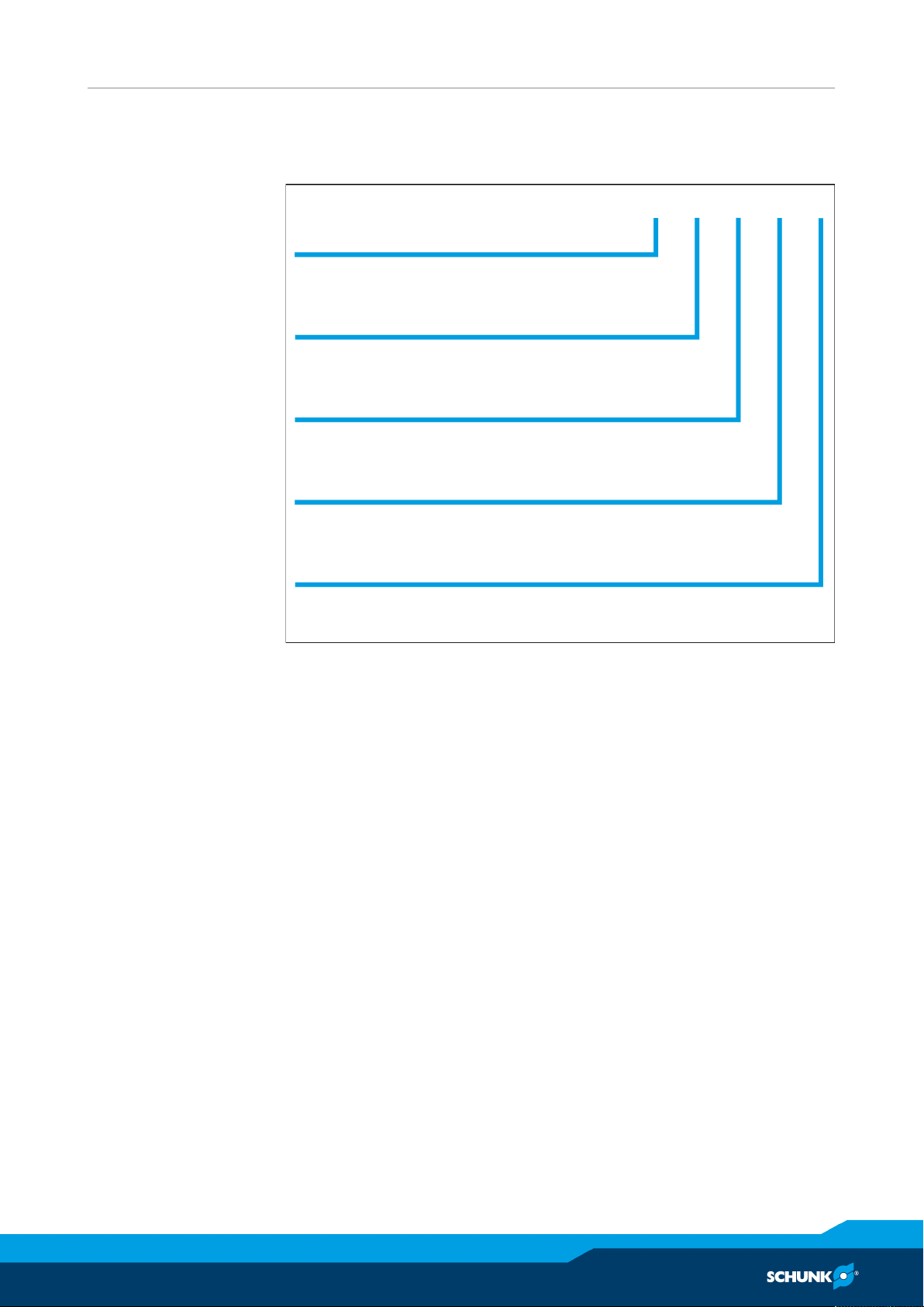
SRU mini-8 - W- M - 4 - EX-
Size
8 12 10 14
Dampening method
S = speed W = soft H = hard
Center position
– = no M = pneumatic
Fluid feed-through
– = no 2 = 2 channels 4 = 2 channels
Explosion-protected version
– = no EX
3.1 Type key
Technical data
10.00 | SRU | Assembly and Operating Manual | en | 389439
19
Page 20

Technical data
3.2 Basic data
Operating data
Designation
Angle of rotation [°] 180
End position adjustability [°]
SRU 8, 10, 12, 14
S/H/W
Min.
Max.
-3
+90
Repeatability [mm] < 0.07
Pressure medium Compressed air, compressed air
quality according to
ISO 8573-1: 7:4:4
Nominal operating pressure
6
[bar]
Min. pressure [bar] 4.5
Max. pressure [bar] 8
More technical data is included in the catalog data sheet.
Whichever is the latest version.
Ambient conditions and operating conditions
Designation
SRU 8, 10, 12,
14
variant S/H
SRU 8, 10, 12,
14
variant W
Ambient temperature [°C]
min.
max.
+5
+60
+5
+90
20
Relative air humidity [%]
min.
max. (free from condensation)
35
85
IP protection class * 65
Noise emission [dB(A)] ≤ 70
* For use in dirty ambient conditions (e.g. sprayed water, vapors,
abrasion or processing dust) SCHUNK offers corresponding
product options as standard. SCHUNK also offers customized
solutions for special applications in dirty ambient conditions.
10.00 | SRU | Assembly and Operating Manual | en | 389439
Page 21
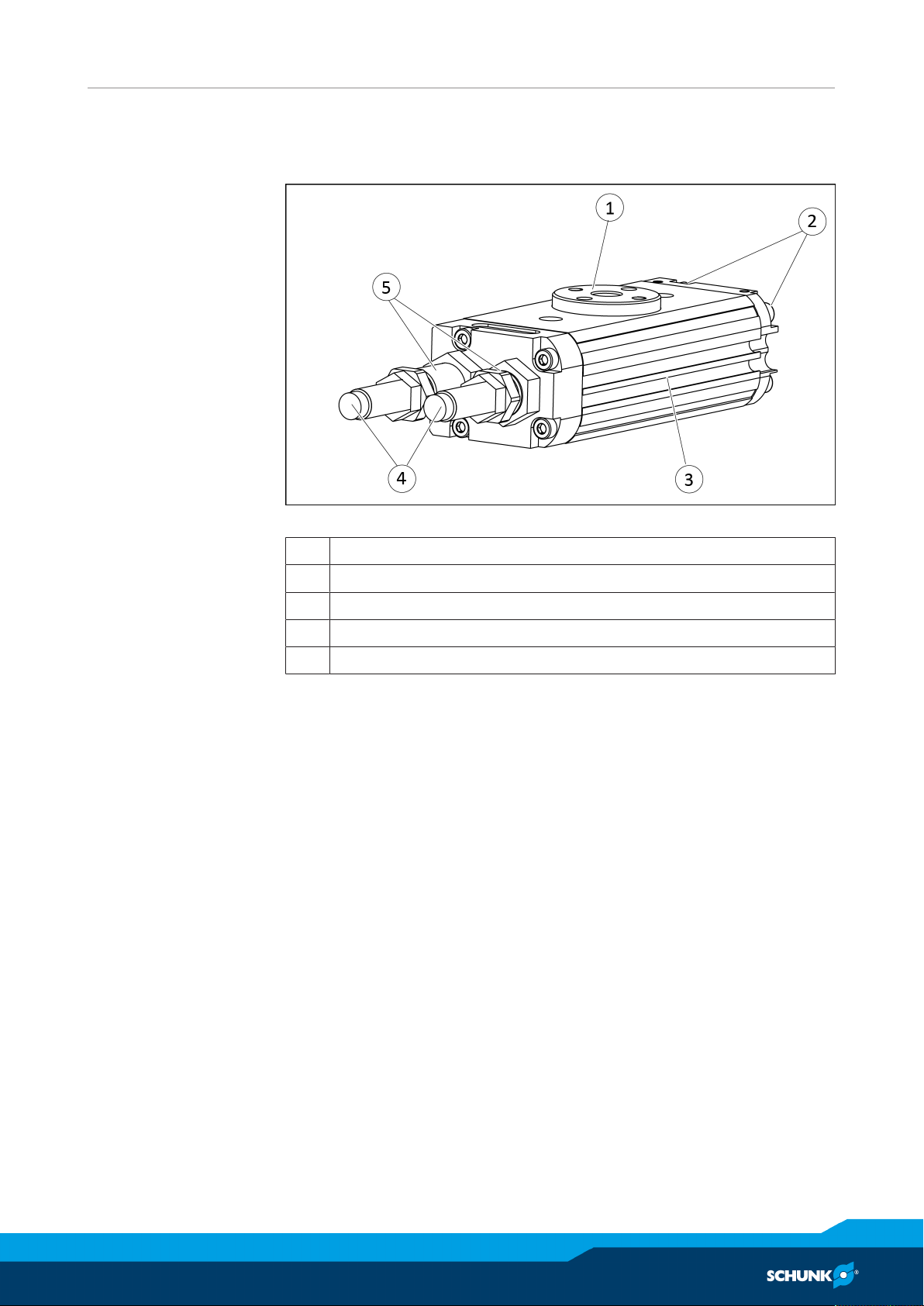
4 Design and description
4.1 Design
Design and description
Pneumatic Rotary Unit, variant "S" displayed
1 Pinion
2 Main air connections
3 Housing with grooves for sensors
4 Shock absorbers
5 Sleeve for adjusting the end positions
4.2 Description
The product is a pneumatic miniature swivel unit for rotating and
swiveling movements with various options.
• Hydraulic dampening (variant H)
• Elastomer dampening (variant S)
• Without dampening (variant W)
• Pneumatic center position (variant M)
• Fluid feed-through
10.00 | SRU | Assembly and Operating Manual | en | 389439
21
Page 22
Assembly
5 Assembly
5.1 Assembling and connecting
WARNING
Risk of injury due to unexpected movements!
If the power supply is switched on or residual energy remains in
the system, components can move unexpectedly and cause
serious injuries.
• Before starting any work on the product: Switch off the power
supply and secure against restarting.
• Make sure, that no residual energy remains in the system.
NOTICE
Material damage due to faulty settings and assembly.
If the end position is approached too aprubtly, the product may
be damaged.
• Ensure the turning / swiveling movement is carried out
without bouncing or bumping.
• Therefore provide sufficient throttling and damping.
• Please observe the information in the catalog data sheet.
NOTICE
Risk of damage to the product!
If during first actuation the exhaust throttle valves are open, the
product may move in an uncontrolled manner.
• Before actuation, check that the exhaust throttle valves are
closed and if necessary close any open ones completely.
NOTE
• Observe the requirements for the compressed air supply,
Technical data [}19].
• In case of compressed air loss (cutting off the energy line), the
product loses its dynamic effects and does not remain in a
secure position. However, the use of a SDV-P pressure
maintenance valve is recommended in this case in order to
maintain the dynamic effect for some time.
22
10.00 | SRU | Assembly and Operating Manual | en | 389439
Page 23

Assembly
Ø Screw the product to the machine/system, Mechanical
connection [}24].
✓ Use centering sleeves.
✓ Observe the tightening torque for the mounting screws, see
the following table.
Ø Fasten attachment with two cylindrical pins and two fastening
screws to the pinion, Mechanical connection [}24].
NOTICE!Insert the cylindrical pins by hand. Do not hammer
the pinion.
Ø In the main air connections "A" and "B", screw in throttle valves
and connect compressed air lines, Pneumatic connection
[}26].
OR with hose-free direct connection:
✓ Mount throttle valves in the supply lines "a" and "b".
✓ Use O-rings from the accessory pack.
Ø Check that all of the throttle valves are closed.
Ø Screw in locking screws in open and not required air
connections where appropriate.
Ø Adjust end positions, Adjustment of the end positions [
Ø Adjust center position if necessary, Adjustment of the central
}
27].
position (Variant M) [}28]
Ø Mount sensor if necessary, Installing the sensors [
Ø Adjust swiveling speed, Setting the speed [
Ø Adjust shock absorber stroke, Adjustment of the shock absorber
}
32].
}
29].
stroke [}34].
10.00 | SRU | Assembly and Operating Manual | en | 389439
23
Page 24
Assembly
5.2 Connections
5.2.1 Mechanical connection
Evenness of the
mounting surface
Mounting
The values apply to the whole mounting surface to which the
product is mounted.
Requirements for evenness of the mounting surface (Dimensions in mm)
Edge length Permissible unevenness
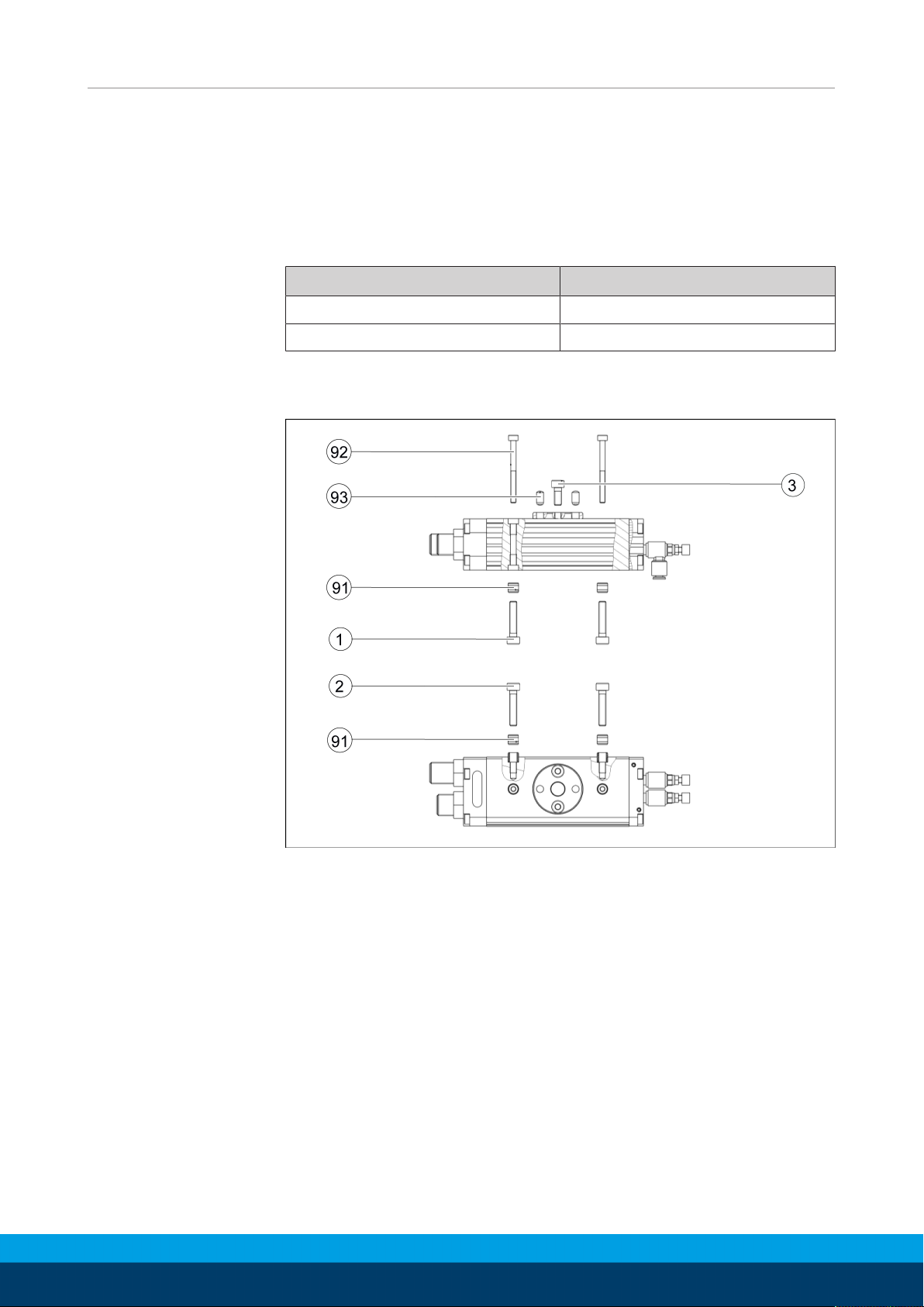
< 100 < 0.02
> 100 < 0.05
The module can be mounted from the top, from the bottom or
from the side.
Assembly options
24
10.00 | SRU | Assembly and Operating Manual | en | 389439
Page 25

Mounting material
Assembly
SRU
Item Designation
8 10 12 14
91 Centering sleeves Ø5 Ø5 Ø6 Ø6
92 Screws for fastening from
above (output side)
M2.5 /
25
deep
M2.5 /
25
deep
M3 /
35
deep
M3 /
35
deep
Max. tightening torque [Nm] 0.75 0.75 1.3 1.3
1 Screws for fastening from
below (underside)
M3 /
4.5
deep
M3 /
4.5
deep
M4 /
6
deep
M4 /
6
deep
Max. tightening torque [Nm] 1.3 1.3 3 3
2 Screws for fastening on the
side
M3 /
4.5
deep
M3 /
4.5
deep
M4 /
6
deep
M4 /
6
deep
Max. tightening torque [Nm] 1.3 1.3 3 3
3 Screws for fastening the
adapter plate
M3 /
4 deep
M3 /
4 deep
M4 /
5 deep
M4 /
5 deep
Max. tightening torque [Nm] 1.3 1.3 3 3
93 Cylindrical pin for securing
the adapter plate
Ø3 x 8 Ø3 x 8 Ø4 x 8 Ø4 x 8
10.00 | SRU | Assembly and Operating Manual | en | 389439
25
Page 26
Assembly
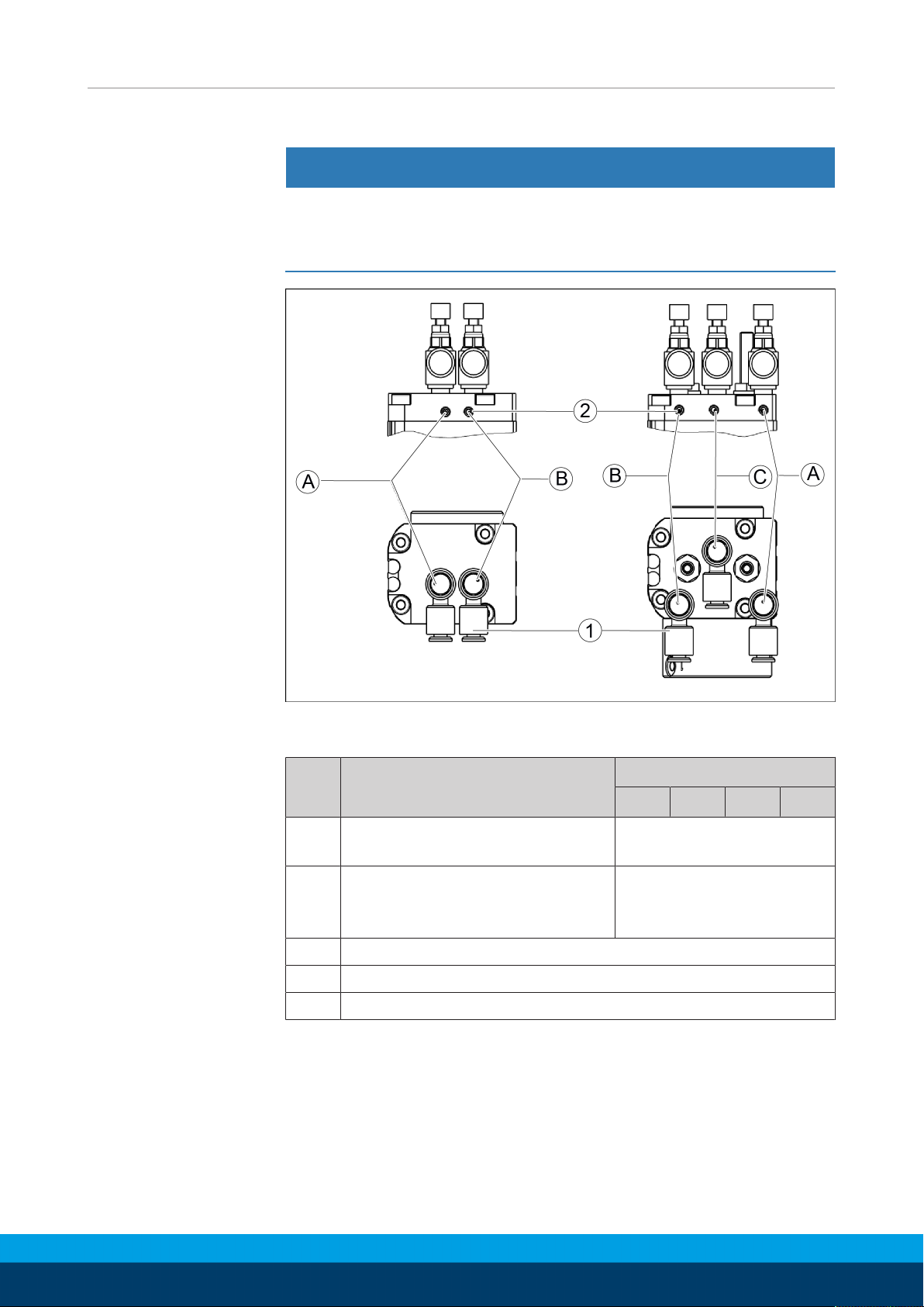
5.2.2 Pneumatic connection
NOTICE
Avoid causing damage by approaching the end positions softly.
• Attach the one-way control valve to the product when
connecting to the center position.
Air connections
Thread diameter of the air connections
SRU
Item Designation
1 Thread diameter hose
8 10 12 14
M3
connection (A ; B ; C)
2 Thread diameter hose-free
M3
direct connection on base side
(a ; b ; c)
A Hose connection für swiveling clockwise
B Hose connection für swiveling counter-clockwise
C Hose connection for swiveling in center position
Further information on the hose-free direct connection contains
the catalog data sheet.
26
10.00 | SRU | Assembly and Operating Manual | en | 389439
Page 27
5.3 Settings
Stop A
Stop B
Connection B
Connection A
Connection A
Connection B
Stop A
Stop B
Variant W
Variant H or
variant S
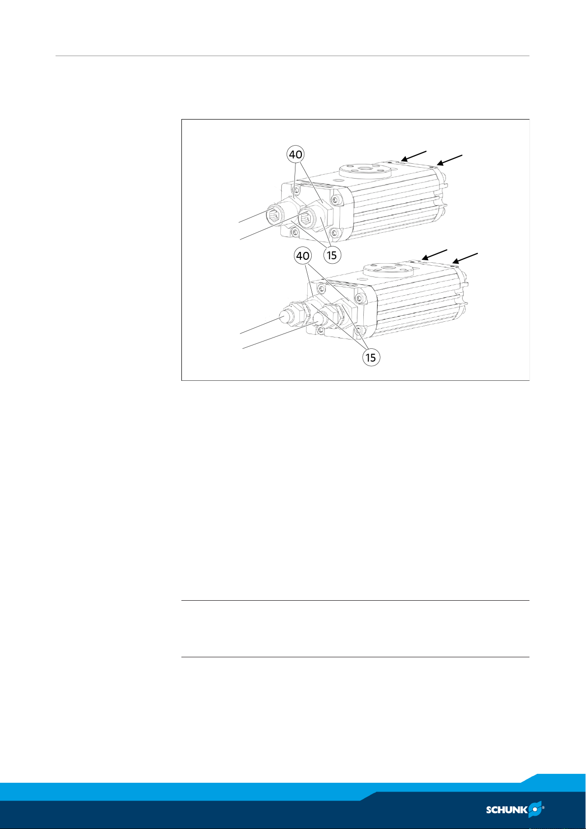
5.3.1 Adjustment of the end positions
Assembly
Adjustment of the end positions
Ø Apply pressure to connection A until the rotary unit has reached
its end position.
Ø Loosen the lock nut (40) at stop B.
Ø Set the end position with sleeve B (5) and stop B (15).
Ø Hold sleeve B (5) and stop B (15) tight and tighten the lock nut (40).
Ø Check the end positions.
Ø Apply pressure to connection B until the rotary unit has reached
its end position.
Ø Loosen the lock nut (40) at stop A.
Ø Set the end position with sleeve A (5) and stop A (15).
Ø Hold sleeve A (5) and stop A (15) tight and tighten the lock nut (40).
Ø Check the end positions.
NOTE
When the lock nut (40) is loosened, air can escape at the sleeve
(5) and at the stop (15). This is due to the design and is normal.
10.00 | SRU | Assembly and Operating Manual | en | 389439
27
Page 28
Assembly
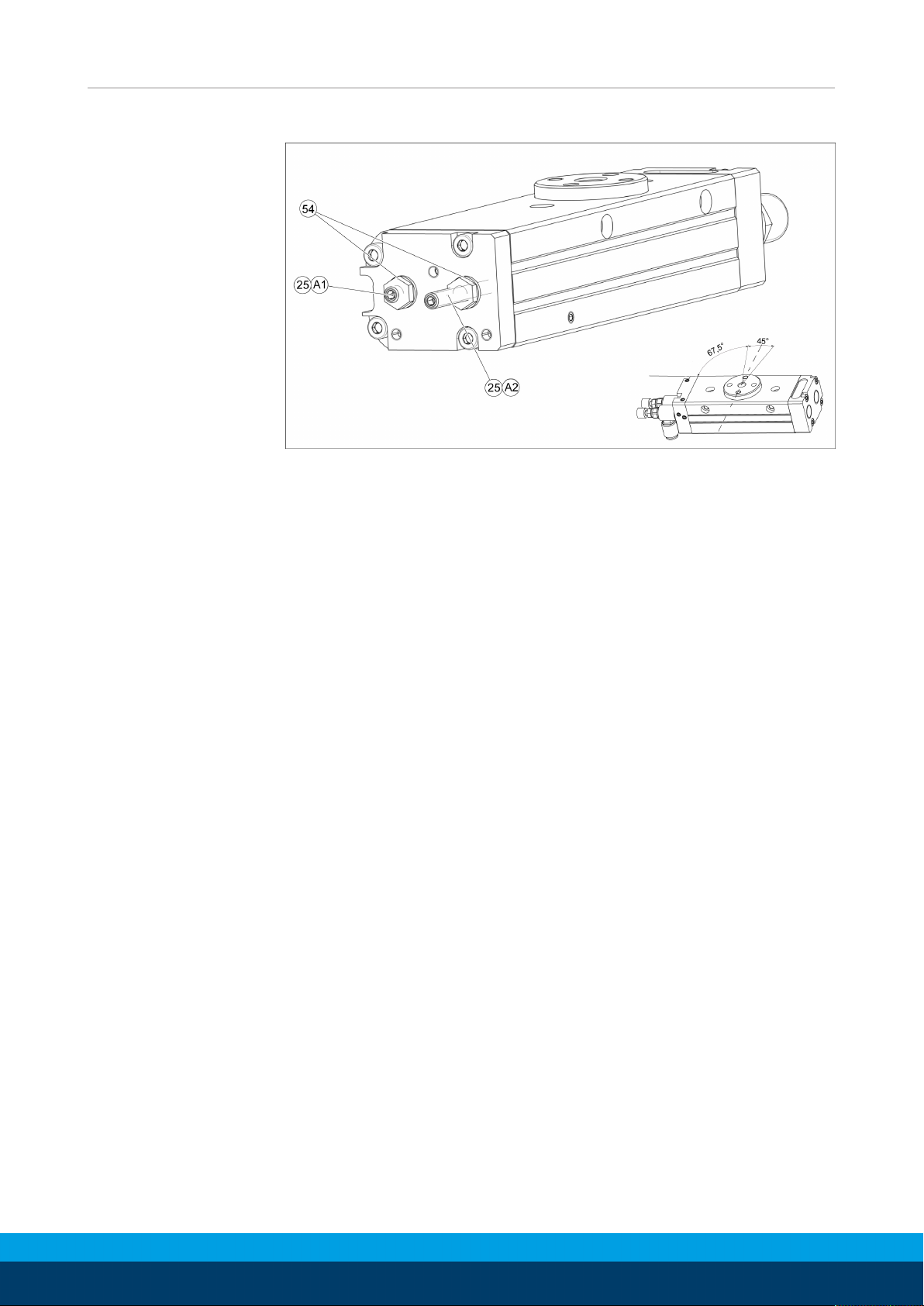
5.3.2 Adjustment of the central position (Variant M)
Adjustment of the central position
Ø Depressurize connections A and B.
Ø Apply air pressure to connection C.
Ø Loosen the lock nuts (54) of the stop spindles (25).
Ø Unscrew stop A2 as far as possible.
Ø Turn the pinion clockwise and keep it pressed against stop A1.
Ø Turn stop A1 until the desired central position has been
reached.
Ø Turn stop A2 until there is no more play in the pinion in the
central position.
Ø Retighten the lock nuts (54) of the stop spindles (25).
Ø Rotate several times to check the correct setting of the central
position.
28
10.00 | SRU | Assembly and Operating Manual | en | 389439
Page 29
5.4 Installing the sensors
NOTE
Observe the assembly and operating manual of the sensor for
mounting and connecting.
The product is prepared for the use of sensors.
• For the exact type designations of suitable sensors, please see catalog datasheet and Overview of sensors [}29].
• For technical data for the suitable sensors, see assembly and
operating manual and catalog datasheet.
– The assembly and operating manual and catalog datasheet
are included in the scope of delivery for the sensors and are
available at schunk.com.
• Information on handling sensors is available at schunk.com or
from SCHUNK contact persons.
5.4.1 Overview of sensors
Assembly
SRU
Designation
8 10 12 14
Magnetic switch MMS 22 X X X X
Programmable magnetic switch MMS 22-PI1 X X X X
10.00 | SRU | Assembly and Operating Manual | en | 389439
29
Page 30

Assembly
5.4.2 Mounting MMS 22 magnetic switch
NOTICE
Material damage due to an incorrect tightening torque!
If the threaded pin is tightened with an incorrect tightening
torque, the product may be damaged.
• Observe a maximum tightening torque of 10 Ncm for the set-
screws.
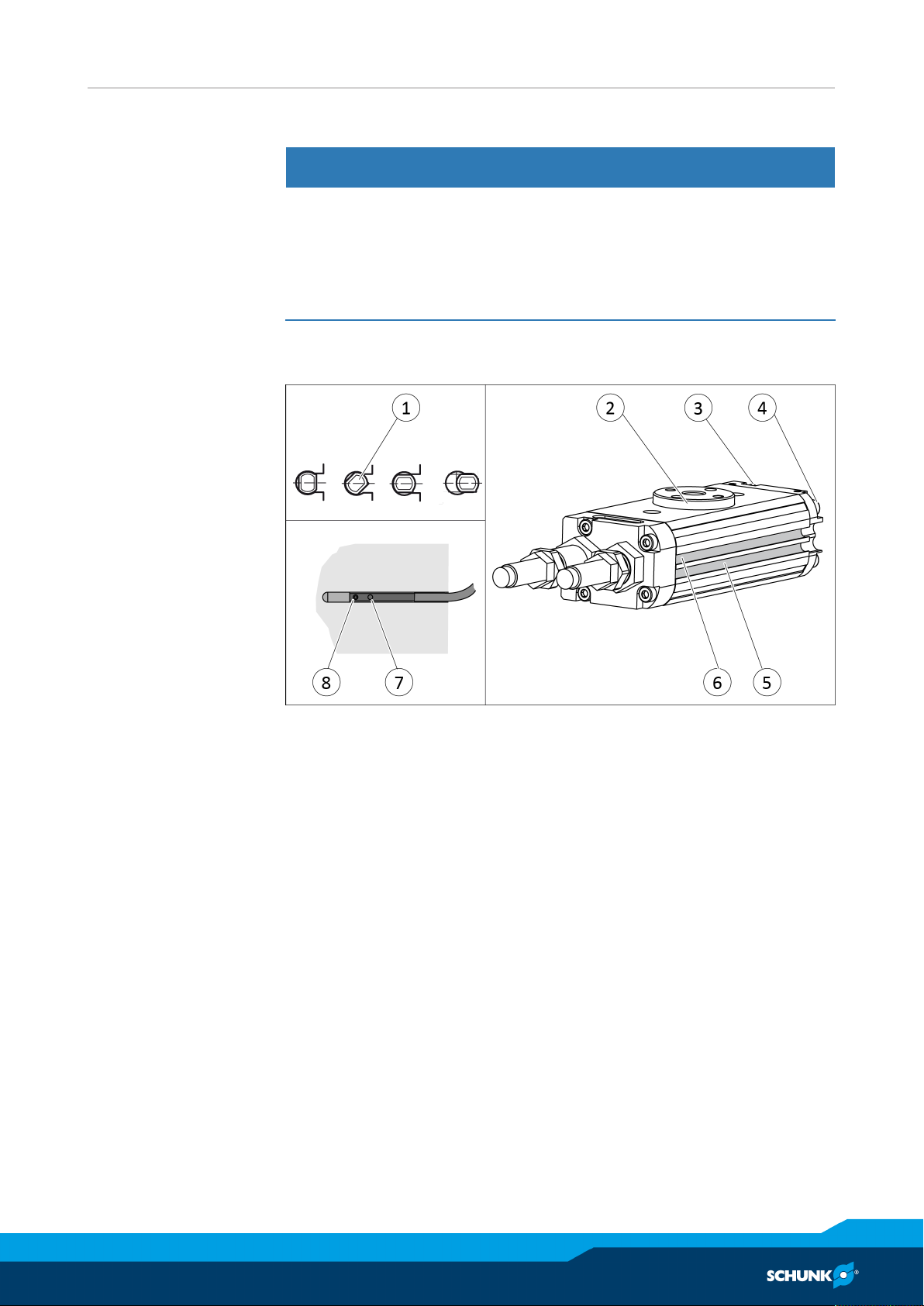
Two groves have been worked into the housing to mount the
sensors.
Center position
variant
Ø Connect sensor and secure cable, see sensor assembly and
operating manual.
Ø Apply air pressure to connection "A" (4).
✓ Pinion (2) swivels towards the end position.
Ø Insert or screw the first sensor (1) into the groove (5).
Ø Move the sensor along the groove until it actuates.
Ø Tighten set screw (8).
✓ Tightening torque: 10 Ncm
Ø Bleed connection "A" (4).
Ø Actuate connection "B" (3).
✓ Pinion (2) swivels into the other end position.
Ø Insert or screw the second sensor (1) into the groove (6).
Ø Move the sensor along the groove until it actuates.
Ø Tighten set screw (8).
✓ Tightening torque: 10 Ncm
Ø Check the switching position and test its function.
Rotate unit in the center position and mount sensor analogously.
30
10.00 | SRU | Assembly and Operating Manual | en | 389439
Page 31
5.4.3 Mounting MMS 22-PI1 programmable magnetic switch
NOTICE
Material damage due to an incorrect tightening torque!
If the threaded pin is tightened with an incorrect tightening
torque, the product may be damaged.
• Observe a maximum tightening torque of 10 Ncm for the set-
screws.
Two groves have been worked into the housing to mount the
sensors.
Assembly
Center position
variant
Ø Connect sensor and secure cable, see sensor assembly and
operating manual.
Ø Apply air pressure to connection "A" (4).
✓ Pinion (2) swivels towards the end position.
Ø Hold teaching tool to the sensor (1) until the sensor flashes.
Ø Insert or screw the sensor (1) into the groove (5), until the
sensor flashes rapidly.
Ø Tighten set screw (8).
✓ Tightening torque: 10 Ncm
Ø Bleed connection "A" (4).
Ø Actuate connection "B" (3).
✓ Pinion (2) swivels into the other end position.
Ø Repeat steps for the second sensor.
Ø Check the switching position and test its function.
Rotate unit in the center position and mount sensor analogously.
10.00 | SRU | Assembly and Operating Manual | en | 389439
31
Page 32
Commissioning
6 Commissioning
NOTICE
Damage to the rotary module possible!
The rotary module can be damaged if it arrives too abruptly in
the end position.
• The rotary motion must reach the end position without jerk or
bounce.
• Therefore flow control valves and shock absorbers must be
used, Setting the speed [}32] and Adjustment of the shock
absorber stroke [}34].
• Please observe the information in the catalog pages.
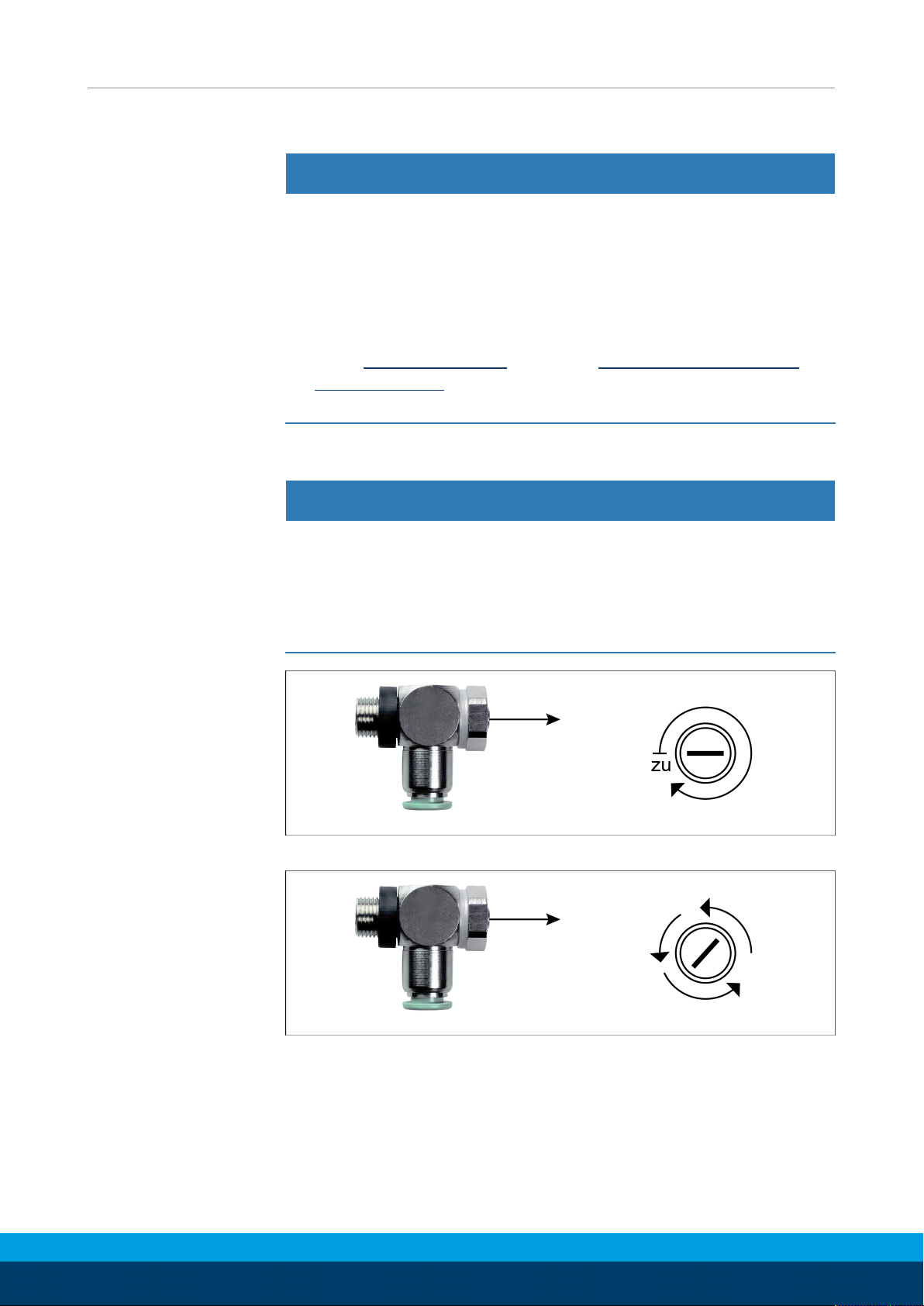
6.1 Setting the speed
NOTICE
Risk of damage to the product!
If the end position is approached too hard, the product may be
damaged.
• Adjust exhaust throttle valve and shock absorber so that the
movement is braked smoothly.
Ø Close exhaust throttle valve completely.
Ø Open exhaust throttle valve until the product starts to move.
32
10.00 | SRU | Assembly and Operating Manual | en | 389439
Page 33

Commissioning
Ø Continue to open the exhaust throttle valve incrementally until
the movement decelerates smoothly.
✓ If the speed is too low, the product will brake too soon and
the end position will be reached too slowly.
✓ If the speed is too high, the product will impact against the
end position and the shock absorber will be overloaded.
NOTE
A smooth motion may also be too slow in many use-cases.
Further settings can be made via the shock absorbers, Adjustment
of the shock absorber stroke [}34].
10.00 | SRU | Assembly and Operating Manual | en | 389439
33
Page 34
Commissioning
Movement
Target position
End position
Target time
Time T
Damping
Movement
Target position
End position
Target time
Time T
Damping
Movement
Target position
End position
Target time
Time T
Damping
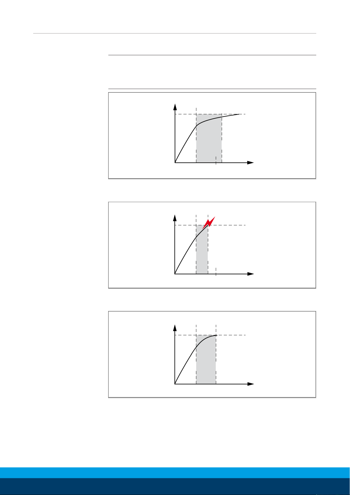
6.2 Adjustment of the shock absorber stroke
NOTE
When received from the factory, the unit is set to utilize the
maximum shock absorber stroke.
The shock absorber stroke is too long and the end position is
reached too slowly.
The shock absorber stroke is too short and the unit arrives in the
end position too abruptly.
Optimal shock absorber stroke.
34
10.00 | SRU | Assembly and Operating Manual | en | 389439
Page 35
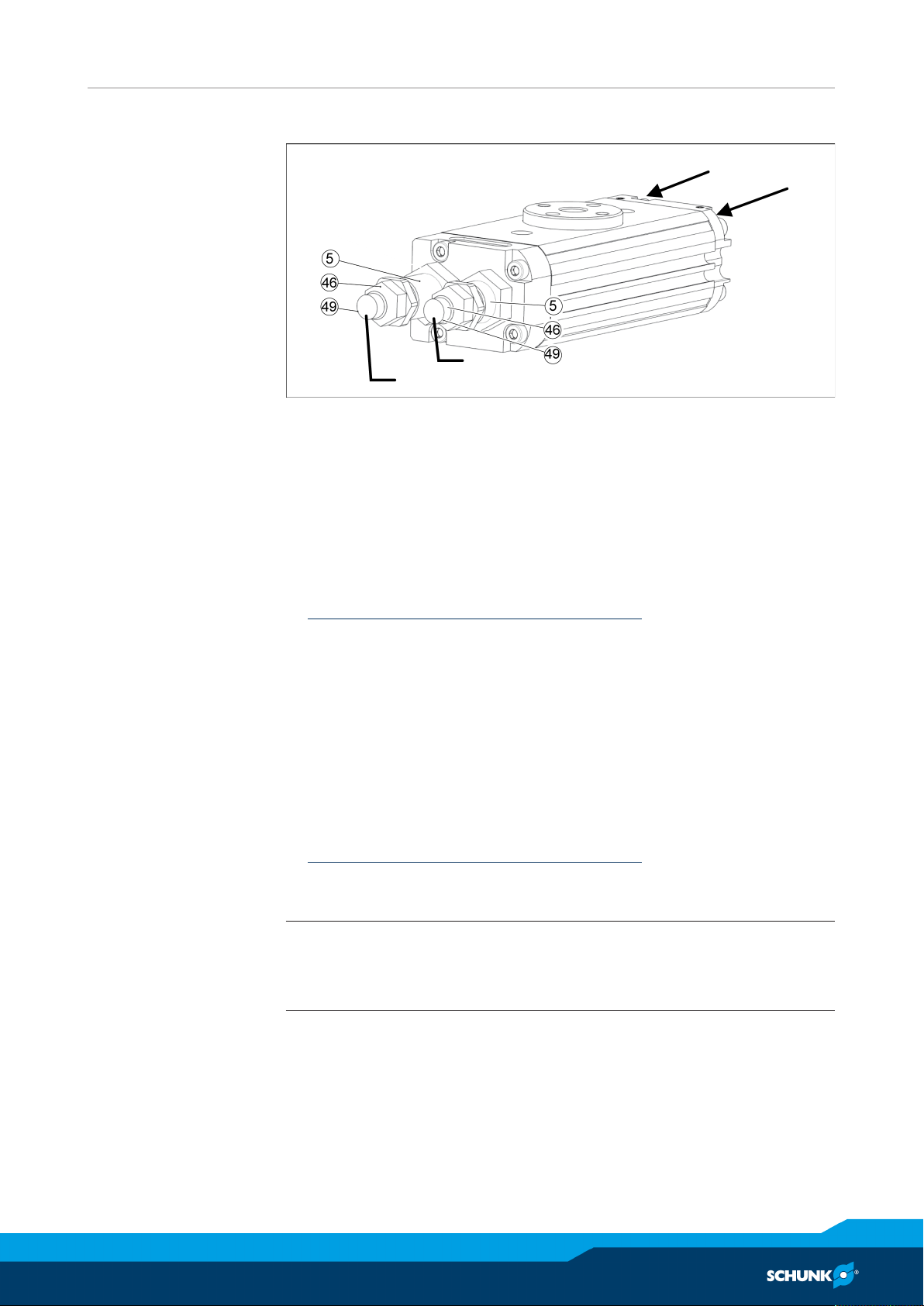
6.2.1 Shock absorber stroke (variant H)
Stop A
Stop B
B
A
Connection
Connection
Adjusting the shock absorber
Commissioning
Adjusting the
dampening for
end position 0°
Adjusting the
dampening for
end position 180°
Ø Apply air pressure to connection A.
Ø Loosen the counter nut (46) from the stop B, by holding the
sleeve (5).
Ø Unscrew the shock absorber (49) to decrease dampening and
swiveling time.
Ø Load and rotate the product to check the shock absorption
effect.NOTICE!The end position must be reached gently,
Adjustment of the shock absorber stroke [}34].
Ø Hold on to the sleeve (5) and shock absorber (49) and tighten
the counter nut (46).
Ø Apply air pressure to connection B.
Ø Loosen the counter nut (46) from the stop A, by holding the
sleeve (5).
Ø Unscrew the shock absorber (49) to decrease dampening and
swiveling time.
Ø Load and rotate the product to check the shock absorption
effect. NOTICE!The end position must be reached gently,
Adjustment of the shock absorber stroke [}34].
Ø Hold on to the sleeve (5) and shock absorber (49) and tighten
the counter nut (46).
NOTE
Air can escape from the shock absorber (49) if the counter nut
(40) is loosened. This is normal and part of the design.
10.00 | SRU | Assembly and Operating Manual | en | 389439
35
Page 36
Commissioning
Stop A
Connection B
Connection
A
Stop B
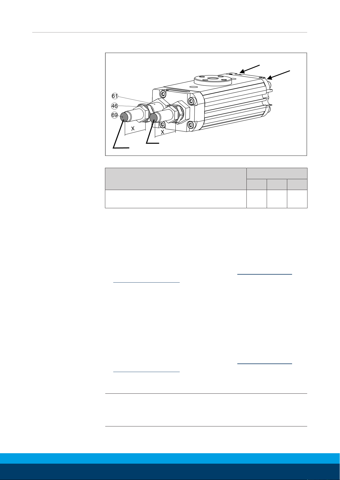
6.2.2 Shock absorber stroke (variant S)
Adjustment of the shock absorber
Pos. X SRU
10 12 14
Setting the shock
absorption for
end position 0°
Setting the shock
absorption for
end position 180°
Maximum screw-in depth of the shock
20.5 24 34
absorber [mm]
Ø Apply air pressure to connection A.
Ø Loosen lock nut (46) on stop B, providing counter support for
the sleeve (61).
Ø Unscrew the shock absorber (69) to decrease shock absorption
and rotation time.
Ø Load and swivel module to check damping effect. NOTICE!The
end position must be approached softly,Adjustment of the
shock absorber stroke [}34]
Ø Hold sleeve (61) and shock absorber (69) tight and retighten the
lock nut (46).
Ø Apply air pressure to connection B.
Ø Loosen lock nut (46) on stop A, providing counter support for
the sleeve (61).
Ø Unscrew the shock absorber (69) to decrease shock absorption
and rotation time.
Ø Load and swivel module to check damping effect. NOTICE!The
end position must be approached softly,Adjustment of the
shock absorber stroke [}34]
Ø Hold sleeve (61) and shock absorber (69) tight and retighten the
lock nut (46) firmly.
NOTE
When the lock nut (40) is loosened, air can escape at the shock
absorber (49). This is due to the design and is normal.
36
10.00 | SRU | Assembly and Operating Manual | en | 389439
Page 37
Troubleshooting
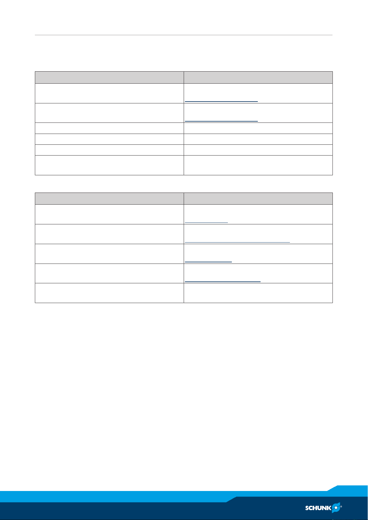
7 Troubleshooting
7.1 Product does not move
Possible cause Corrective action
Pressure drops below minimum. Check air supply.
Pneumatic connection [}26]
Compressed air lines switched. Check compressed air lines.
Pneumatic connection [}26]
Proximity switch defective or set incorrect. Readjust or change sensor.
Unused air connections open. Close unused air connections.
Flow control valve closed. Open the flow control valve.
Component part defective. Replace component or send it to SCHUNK
for repair.
7.2 Product does not travel through the entire stroke
Possible cause Corrective action
Accumulation of dirt between stop / sleeve
and pistons.
End positions are adjusted incorrectly. Adjust end position.
Pressure drops below minimum. Check air supply.
Mounting surface is not sufficiently flat. Check the evenness of the mounting surface.
Component part defective. Send product with a SCHUNK repair order or
Clean and if necessary re-lubricate.
Maintenance [}39]
Adjustment of the end positions [}27]
Technical data [}19]
Mechanical connection [}24]
dismantle product.
10.00 | SRU | Assembly and Operating Manual | en | 389439
37
Page 38
Troubleshooting
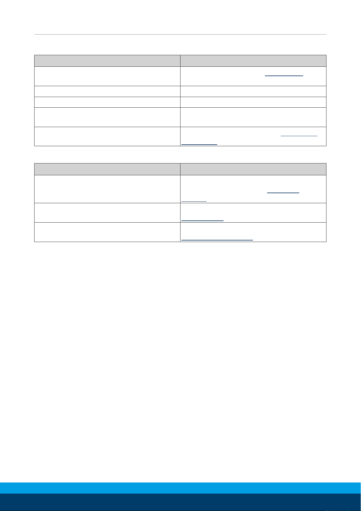
7.3 Product rotates jerkily
Possible cause Corrective action
Too little grease in the mechanical guiding
Clean and lubricate product., Maintenance [}39]
areas.
Compressed air lines blocked. Check compressed air lines of damage.
Mounting surface is not sufficiently flat. Check the evenness of the mounting surface.
One-way flow control valve is missing or
adjustet incorrectly.
Install and adjust one-way flow control
valve.
Loading too large. Check the permissible weight., Mechanical
connection [}24]
7.4 Torque diminishes?
Possible cause Corrective action
Compressed air can escape. Check seals, if necessary, disassemble the
product and replace seals. Dismantle
product [}40]
Too much grease in the mechanical
movement space.
Pressure drops below minimum. Check air supply.
Clean and lubricate product.
Maintenance [}39]
Pneumatic connection [}26]
38
10.00 | SRU | Assembly and Operating Manual | en | 389439
Page 39
Maintenance
8 Maintenance
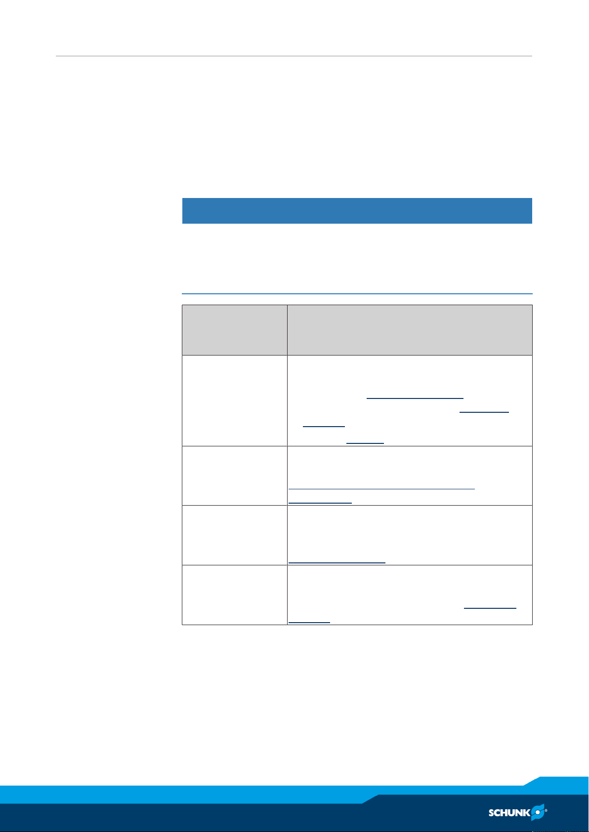
8.1 Notes
Original spare parts
Use only original spare parts of SCHUNK when replacing spare and
wear parts.
8.2 Maintenance interval
NOTICE
Material damage due to hardening lubricants!
Lubricants harden more quickly at temperatures above 60°C,
leading to possible product damage.
• Reduce the lubricant intervals accordingly.
Interval
(million cycles)
for SRU 8 - 14
2 Clean all parts thoroughly, check for damage
2 Treat all grease areas with lubricant.
2 For H variant:
2 For S variant:
Maintenance work
and wear, if necessary replace seals and
wearing parts, Dismantle product [}40].
• Position of the wearing parts, Assembly
drawing [}42]
• Seal kit, Seal kit [}8]
Oil or grease bare outside steel parts.
Lubricants/Lubrication points (basic
lubrication) [}40].
Check that the shock absorber is working, if
necessary replace the shock absorber,
Dismantle product [}40].
Check that the elastomer is working, if
necessary replace the elastomer, Dismantle
product [}40].
10.00 | SRU | Assembly and Operating Manual | en | 389439
39
Page 40
Maintenance
8.3 Lubricants/Lubrication points (basic lubrication)
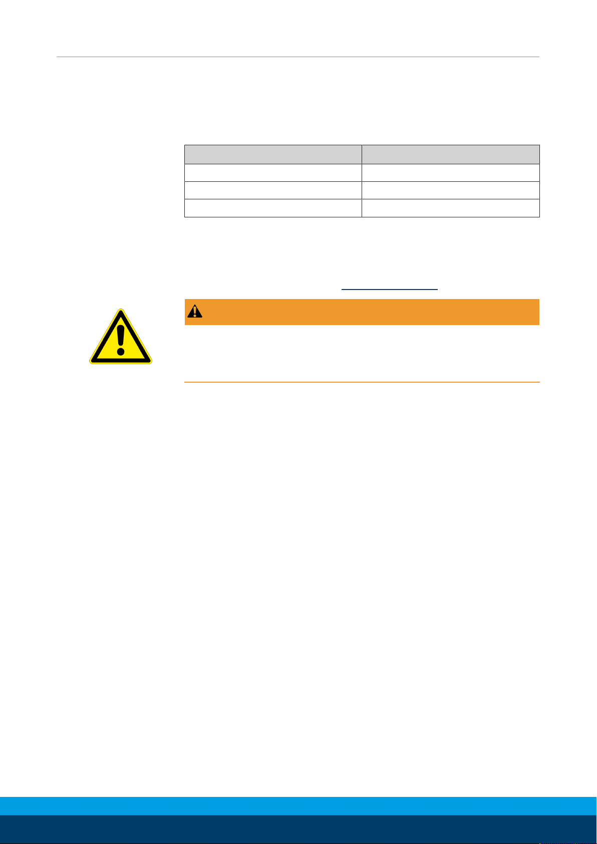
SCHUNK recommends the lubricants listed.
During maintenance, treat all greased areas with lubricant. Thinly
apply lubricant with a lint-free cloth.
Lubricant point Lubricant
The teeth and the pinion Molykote BR 2 plus
Metallic sliding surfaces Renolit HLT 2
All seals Renolit HLT 2
8.4 Disassembly and assembly
8.4.1 Dismantle product
Position of the item numbers Assembly drawing [}42]
WARNING
Risk of injury when machine/system moves unexpectedly!
• Switch off power supply before assembly and installation.
• Make sure that no residual energy remains in the system.
Ø Remove the compressed air hoses.
Ø Unscrew the screws (34) and remove the cover 1 (3).
Ø Unscrew the screws (60) and remove the cover 2 (14).
Ø Mark the installation position of the piston (2) and the pinion
(6 / 16).
Ø Version with media feed-through: Unscrew the screws (41) and
remove the cover (18).
Ø Disassemble the safety ring (33) on the pinion.
Ø Type SRU 8 and Type SRU 10: Remove the washer (7).
Ø Press the pinion (6 / 16) upward out of the housing (1).
Ø Servicing the module.
40
10.00 | SRU | Assembly and Operating Manual | en | 389439
Page 41
8.4.2 Notes for assembly
Assembly takes place in the opposite order to disassembly.
Observe the following:
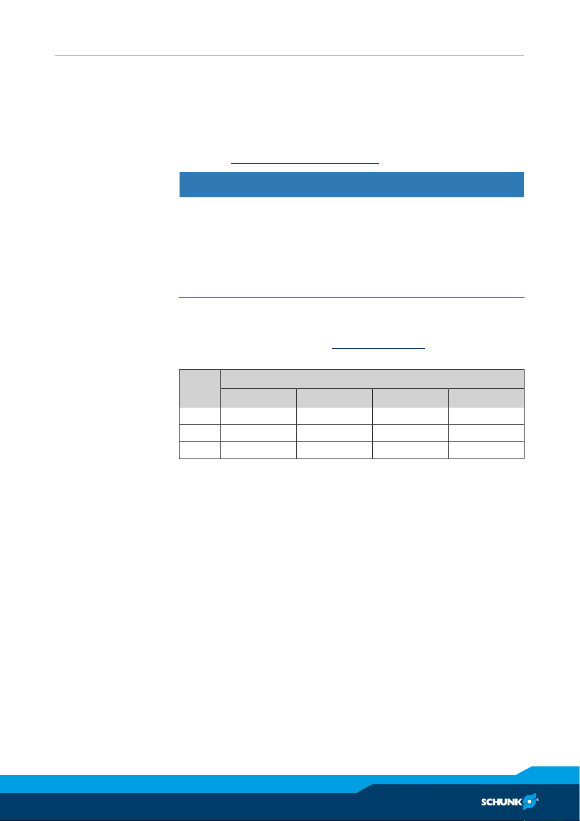
• Unless otherwise specified, secure all screws and nuts with Loctite no. 243 and tighten with the appropriate tightening torque.Tightening torque for screws [}41]
NOTICE
Material damage due to incorrect assembly!
The O-rings (42) can become damaged during assembly.
• Install the cover for the internal air feed-through (18)
carefully.
• The cover for the internal air feed-through (18) can be
installed rotated by 180°, if required.
8.4.3 Tightening torque for screws
Maintenance
Position of the item numbers Assembly drawing [}42]
Specified in Nm
Item SRU
8 10 12 14
34 0.75 0.75 1.3 1.3
41 0.75 0.75 1.3 1.3
60 0.75 0.75 1.3 1.3
10.00 | SRU | Assembly and Operating Manual | en | 389439
41
Page 42
Maintenance
8.4.4 Assembly drawing
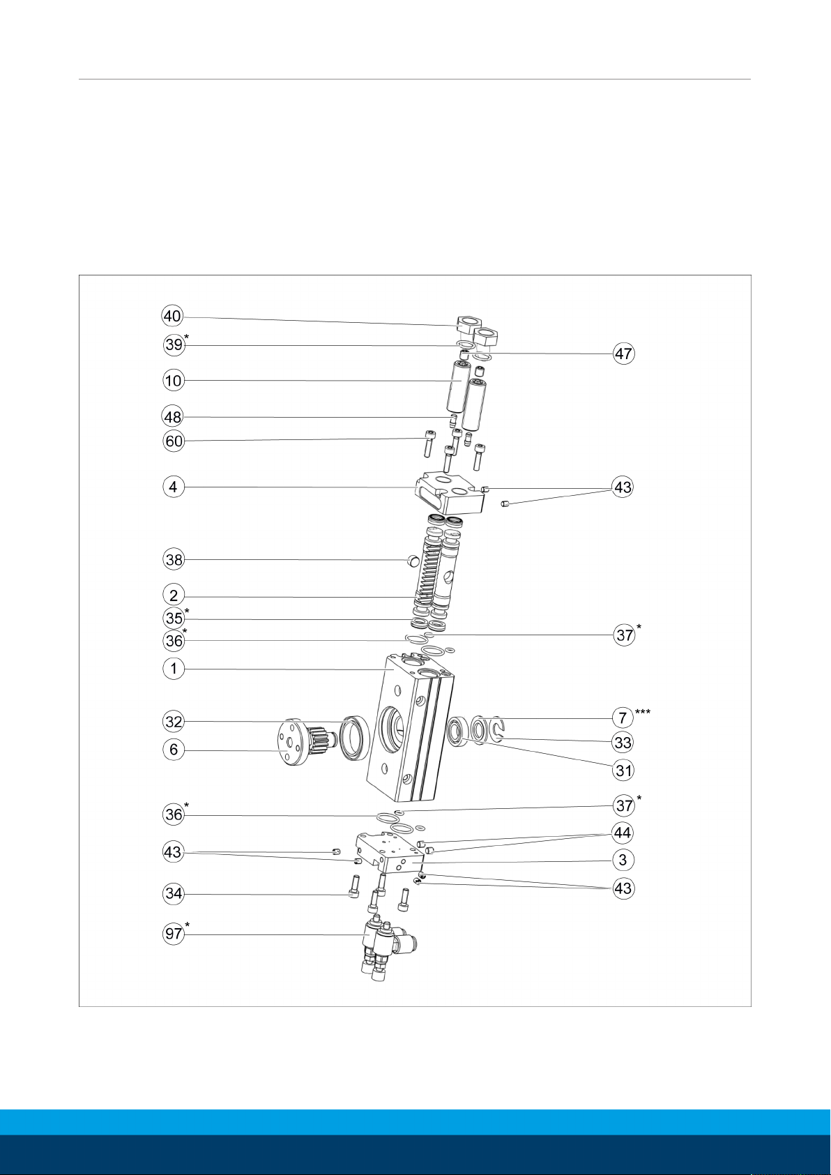
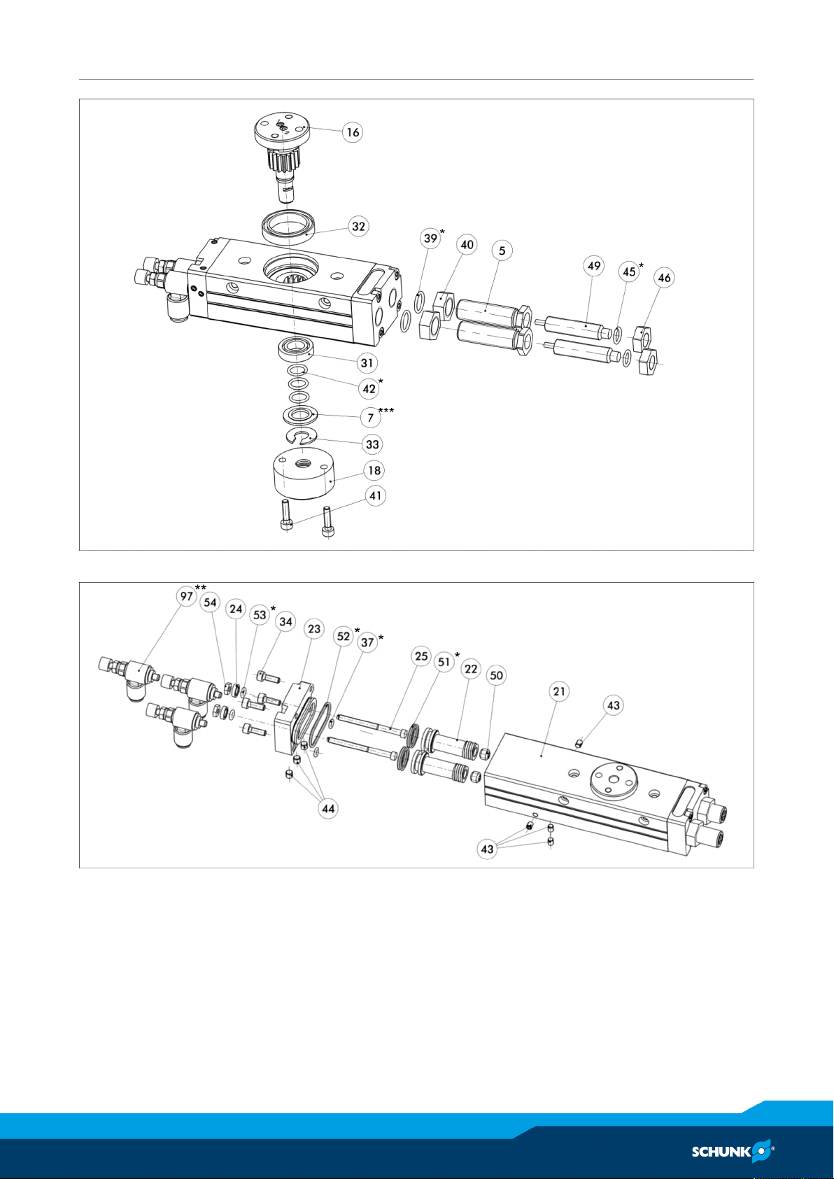
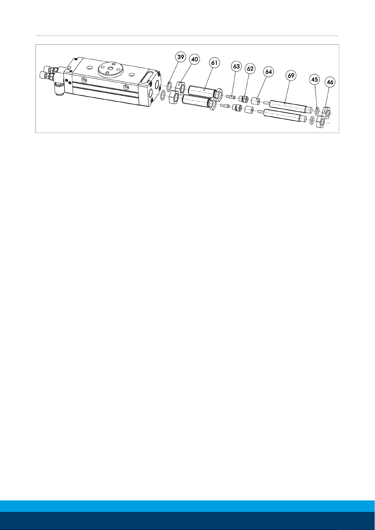
The following figures are example images.
They serve for illustration and assignment of the spare parts.
Variations are possible depending on size and variant.
* Wearing part, replace during maintenance. Included in the
seal kit. Seal kit can only be ordered completely.
** nur bei SRU 8 und SRU 10
Assembly of rotary unit
42
10.00 | SRU | Assembly and Operating Manual | en | 389439
Page 43
Maintenance
Assembly of fluid feed-through and hydraulic damping
Assembly of rotary unit with central position
10.00 | SRU | Assembly and Operating Manual | en | 389439
43
Page 44
Maintenance
Assembly of rotary unit with damper-elastomer-damping
44
10.00 | SRU | Assembly and Operating Manual | en | 389439
Page 45

Translation of original declaration of incorporation
9 Translation of original declaration of incorporation
in terms of the Directive 2006/42/EG, Annex II, Part 1.B of the European Parliament and of
the Council on machinery.
Manufacturer/
Distributor
SCHUNK GmbH & Co. KG Spann- und Greiftechnik
Bahnhofstr. 106 – 134
D-74348 Lauffen/Neckar
We hereby declare that on the date of the declaration the following partly completed
machine complied with all basic safety and health regulations found in the directive
2006/42/EC of the European Parliament and of the Council on machinery. The declaration
is rendered invalid if modifications are made to the product.
Product designation: Pneumatic Rotary Unit / SRU / pneumatic
ID number 0356810 ... 0356877 0356930 ... 0356973
The partly completed machine may not be put into operation until conformity of the
machine into which the partly completed machine is to be installed with the provisions of
the Machinery Directive (2006/42/EC) is confirmed.
Applied harmonized standards, especially:
EN ISO 12100:2010 Safety of machinery - General principles for design -
Risk assessment and risk reduction
The manufacturer agrees to forward on demand the relevant technical documentation for
the partly completed machinery in electronic form to national authorities.
The relevant technical documentation according to AnnexVII, Part B, belonging to the
partly completed machinery, has been created.
Person authorized to compile the technical documentation:
Robert Leuthner, Address: see manufacturer's address
Lauffen/Neckar, May 2019 p.p. Ralf Winkler,
Manager for development
of gripping system components
10.00 | SRU | Assembly and Operating Manual | en | 389439
45
Page 46

Annex to Declaration of Incorporation
10 Annex to Declaration of Incorporation
according 2006/42/EG, Annex II, No. 1 B
1.Description of the essential health and safety requirements pursuant to 2006/42/EC,
Annex I that are applicable and that have been fulfilled with:
Product designation Pneumatic Rotary Unit
Type designation SRU
ID number 0356810 ... 0356877 0356930 ... 0356973
To be provided by the System Integrator for the overall machine ⇓
Fulfilled for the scope of the partly completed machine ⇓
Not relevant ⇓
1.1 Essential Requirements
1.1.1 Definitions X
1.1.2 Principles of safety integration X
1.1.3 Materials and products X
1.1.4 Lighting X
1.1.5 Design of machinery to facilitate its handling X
1.1.6 Ergonomics X
1.1.7 Operating positions X
1.1.8 Seating X
1.2 Control Systems
1.2.1 Safety and reliability of control systems X
1.2.2 Control devices X
1.2.3 Starting X
1.2.4 Stopping X
1.2.4.1 Normal stop X
1.2.4.2 Operational stop X
1.2.4.3 Emergency stop X
1.2.4.4 Assembly of machinery X
1.2.5 Selection of control or operating modes X
1.2.6 Failure of the power supply X
1.3 Protection against mechanical hazards
1.3.1 Risk of loss of stability X
1.3.2 Risk of break-up during operation X
1.3.3 Risks due to falling or ejected objects X
1.3.4 Risks due to surfaces, edges or angles X
1.3.5 Risks related to combined machinery X
46
10.00 | SRU | Assembly and Operating Manual | en | 389439
Page 47

Annex to Declaration of Incorporation
1.3 Protection against mechanical hazards
1.3.6 Risks related to variations in operating conditions X
1.3.7 Risks related to moving parts X
1.3.8 Choice of protection against risks arising from moving parts X
1.3.8.1 Moving transmission parts X
1.3.8.2 Moving parts involved in the process X
1.3.9 Risks of uncontrolled movements X
1.4 Required characteristics of guards and protective devices
1.4.1 General requirements X
1.4.2 Special requirements for guards X
1.4.2.1 Fixed guards X
1.4.2.2 Interlocking movable guards X
1.4.2.3 Adjustable guards restricting access X
1.4.3 Special requirements for protective devices X
1.5 Risks due to other hazards
1.5.1 Electricity supply X
1.5.2 Static electricity X
1.5.3 Energy supply other than electricity X
1.5.4 Errors of fitting X
1.5.5 Extreme temperatures X
1.5.6 Fire X
1.5.7 Explosion X
1.5.8 Noise X
1.5.9 Vibrations X
1.5.10 Radiation X
1.5.11 External radiation X
1.5.12 Laser radiation X
1.5.13 Emissions of hazardous materials and substances X
1.5.14 Risk of being trapped in a machine X
1.5.15 Risk of slipping, tripping or falling X
1.5.16 Lightning X
1.6 Maintenance
1.6.1 Machinery maintenance X
1.6.2 Access to operating positions and servicing points X
1.6.3 Isolation of energy sources X
1.6.4 Operator intervention X
1.6.5 Cleaning of internal parts X
10.00 | SRU | Assembly and Operating Manual | en | 389439
47
Page 48

Annex to Declaration of Incorporation
1.7 Information
1.7.1 Information and warnings on the machinery X
1.7.1.1 Information and information devices X
1.7.1.2 Warning devices X
1.7.2 Warning of residual risks X
1.7.3 Marking of machinery X
1.7.4 Instructions X
1.7.4.1 General principles for the drafting of instructions X
1.7.4.2 Contents of the instructions X
1.7.4.3 Sales literature X
The classification from Annex 1 is to be supplemented from here
forward.
2 Supplementary essential health and safety requirements for certain
categories of machinery
2.1 Foodstuffs machinery and machinery for cosmetics or pharmaceutical
products
2.2 Portable hand-held and/or guided machinery X
2.2.1 Portable fixing and other impact machinery X
2.3 Machinery for working wood and material with similar physical
characteristics
3 Supplementary essential health and safety requirements to offset
X
hazards due to the mobility of machinery
4 Supplementary essential health and safety requirements to offset
X
hazards due to lifting operations
5 Supplementary essential health and safety requirements for machinery
intended for underground work
6 Supplementary essential health and safety requirements for machinery
X
presenting particular hazards due to the lifting of persons
X
X
X
X
48
10.00 | SRU | Assembly and Operating Manual | en | 389439
 Loading...