

Schumacher SE-2254,SE-3612,SE-3000,SE-2352,SE-4020,SE-4022,SE-5025,SE-6030,SE-8050 Owner's Manual
0099001275-00
Manual Battery Charger
Cargador de Batería Manual
Models / Modelos: SE-2254, SE-2352, SE-3000, SE-3612,
SE-4020, SE-4022, SE-5025, SE-6030,
SE-8050
READ THE ENTIRE MANUAL BEFORE USING THIS PRODUCT.
FAILURE TO DO SO COULD RESULT IN SERIOUS INJURY OR DEATH.
LEA EL MANUAL COMPLETO ANTES DE UTILIZAR ESTE PRODUCTO. CUALQUIER
FALLA PODRÍA RESULTAR EN SERIAS LESIONES O PODRÍA SER MORTAL.
OWNER’S MANUAL
MANUAL DEL USUARIO
DO NOT RETURN THIS PRODUCT TO THE STORE!
Call Customer Service for assistance: 800-621-5485
¡NO LO DEVUELVA ESTE PRODUCTO A LA TIENDA!
Llame a Servicios al Cliente para asistencia: 800-621-5485
• 2 •
IMPORTANT: READ AND SAVE THIS SAFETY AND INSTRUCTION MANUAL.
SAVE THESE INSTRUCTIONS – This manual will show you how to use your
charger safely and effectively. Please read, understand and follow these instructions
and precautions carefully, as this manual contains important safety and operating
instructions. The safety messages used throughout this manual contain a signal word, a
message and an icon.
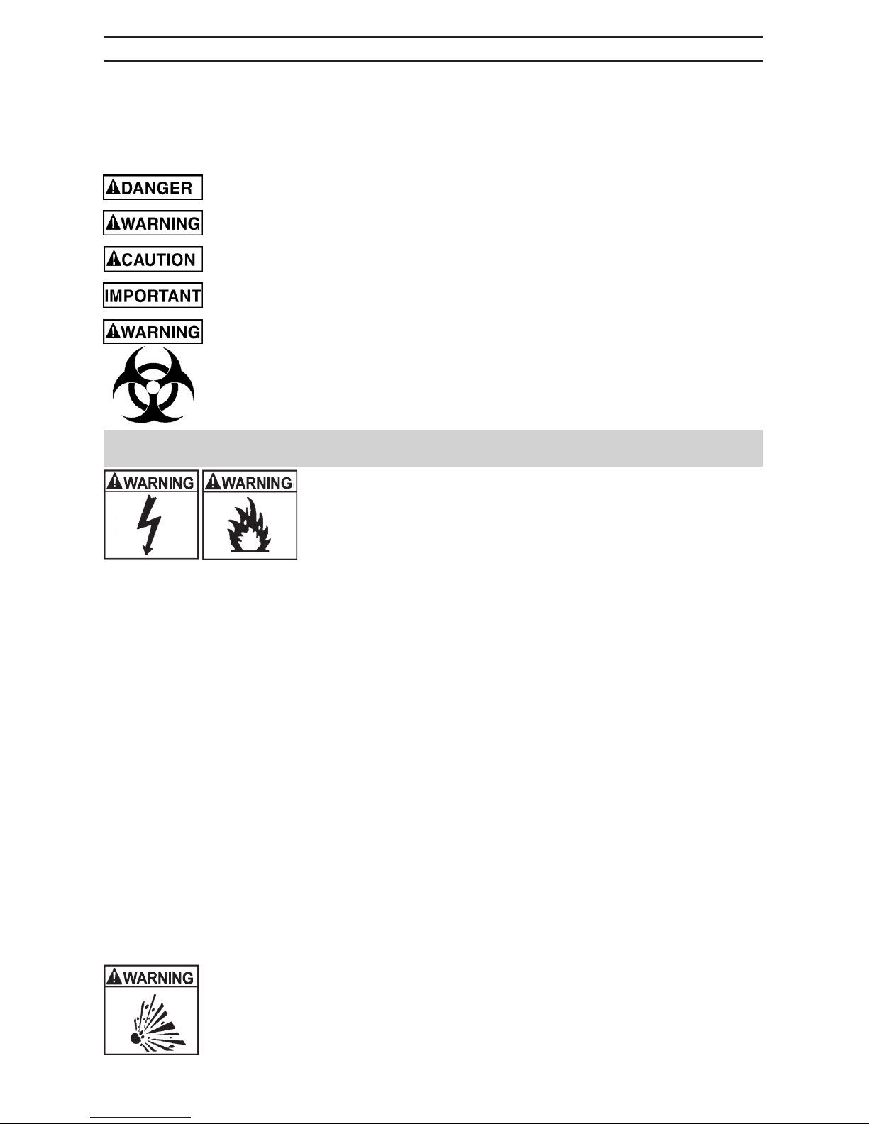
The signal word indicates the level of the hazard in a situation.
Indicates an imminently hazardous situation which, if not avoided, will result in
death or serious injury to the operator or bystanders.
Indicates a potentially hazardous situation which, if not avoided, could result in
death or serious injury to the operator or bystanders.
Indicates a potentially hazardous situation which, if not avoided, could result in
moderate or minor injury to the operator or bystanders.
Indicates a potentially hazardous situation which, if not avoided, could result in
damage to the equipment or vehicle or property damage.
Pursuant to California Proposition 65, this product contains chemicals known to
the State of California to cause cancer and birth defects or other reproductive
harm. Wash hands after handling.
1. IMPORTANT SAFETY INSTRUCTIONS – SAVE THESE INSTRUCTIONS.
This manual contains important safety and operating instructions.
RISK OF ELECTRIC SHOCK OR FIRE.
1.1 Keep out of reach of children.
1.2 Do not expose the charger to rain or snow.
1.3 Use only recommended attachments. Use of an attachment
not recommended or sold by Schumacher® Electric Corporation
may result in a risk of re, electric shock or injury to persons or damage to property.
1.4 To reduce the risk of damage to the electric plug or cord, pull by the plug rather than the
cord when disconnecting the charger.
1.5 An extension cord should not be used unless absolutely necessary. Use of an improper
extension cord could result in a risk of re and electric shock. If an extension cord must
be used, make sure:
• That the pins on the plug of the extension cord are the same number, size and shape
as those of the plug on the charger.
• That the extension cord is properly wired and in good electrical condition.
• That the wire size is large enough for the AC ampere rating of the charger as
specied in section 8.
1.6 To reduce the risk of electric shock, unplug the charger from the outlet before attempting
any maintenance or cleaning. Simply turning off the controls will not reduce this risk.
1.7 Do not operate the charger with a damaged cord or plug; have the cord or plug replaced
immediately by a qualied service person. (Call customer service at 1-800-621-5485.)
1.8 Do not operate the charger if it has received a sharp blow, been dropped or otherwise
damaged in any way; take it to a qualied service person. (Call customer service at
1-800-621-5485.)
1.9 Do not disassemble the charger; take it to a qualied service person when service or
repair is required. Incorrect reassembly may result in a risk of re or electric shock. (Call
customer service at 1-800-621-5485.)
RISK OF EXPLOSIVE GASES.
1.10 WORKING IN THE VICINITY OF A LEAD-ACID BATTERY IS
DANGEROUS. BATTERIES GENERATE EXPLOSIVE GASES DURING
NORMAL BATTERY OPERATION. FOR THIS REASON, IT IS OF UTMOST
IMPORTANCE THAT YOU FOLLOW THE INSTRUCTIONS EACH TIME YOU
USE THE CHARGER.
• 3 •
1.11 To reduce the risk of a battery explosion, follow these instructions and those published
by the battery manufacturer and the manufacturer of any equipment you intend to use
in the vicinity of the battery. Review the cautionary markings on these products and on
the engine.
2. PERSONAL PRECAUTIONS
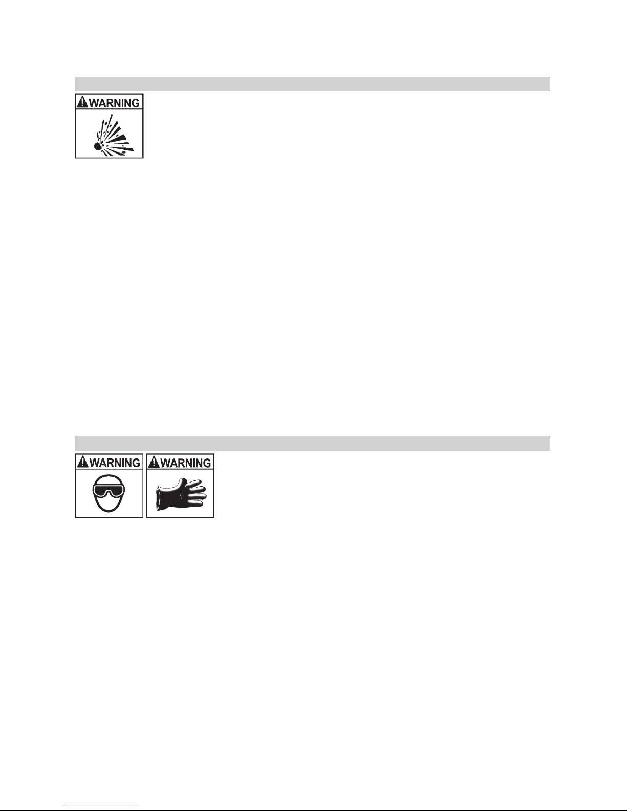
RISK OF EXPLOSIVE GASES.
2.1 NEVER smoke or allow a spark or ame in the vicinity of a battery or engine.
2.2 Remove personal metal items such as rings, bracelets, necklaces and
watches when working with a lead-acid battery. A lead-acid battery can produce
a short-circuit current high enough to weld a ring or the like to metal, causing a
severe burn.
2.3 Be extra cautious, to reduce the risk of dropping a metal tool onto the battery. It might
spark or short-circuit the battery or other electrical part that may cause an explosion.
2.4 Use this charger for charging LEAD-ACID batteries only. It is not intended to supply power
to a low voltage electrical system other than in a starter-motor application. Do not use
this battery charger for charging dry-cell batteries that are commonly used with home
appliances. These batteries may burst and cause injury to persons and damage to property.
2.5 NEVER charge a frozen battery.
2.6 NEVER overcharge a battery.
2.7 Consider having someone nearby to come to your aid when you work near a
lead-acid battery.
2.8 Have plenty of fresh water and soap nearby in case battery acid contacts your skin,
clothing or eyes.
2.9 Wear complete eye and body protection, including safety goggles and protective
clothing. Avoid touching your eyes while working near the battery.
2.10 If battery acid contacts your skin or clothing, immediately wash the area with soap and
water. If acid enters your eye, immediately ood the eye with cold running water for at
least 10 minutes and get medical attention right away.
2.11 If battery acid is accidentally swallowed, drink milk, the whites of eggs or water. DO NOT
induce vomiting. Seek medical attention immediately.
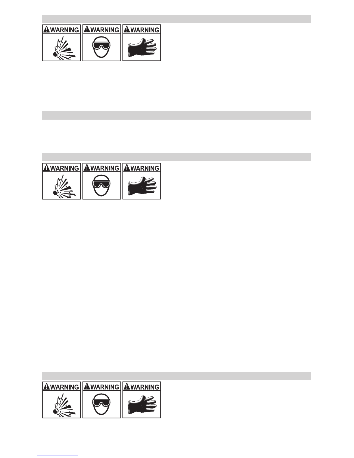
3. PREPARING TO CHARGE
RISK OF CONTACT WITH BATTERY ACID. BATTERY ACID IS A
HIGHLY CORROSIVE SULFURIC ACID.
3.1 If it is necessary to remove the battery from the vehicle to
charge it, always remove the grounded terminal rst. Make sure all
of the accessories in the vehicle are off to prevent arcing.
3.2 Be sure the area around the battery is well ventilated while
the battery is being charged.
3.3 Clean the battery terminals before charging the battery. During cleaning, keep airborne
corrosion from coming into contact with your eyes, nose and mouth. Use baking soda
and water to neutralize the battery acid and help eliminate airborne corrosion. Do not
touch your eyes, nose or mouth.
3.4 Add distilled water to each cell until the battery acid reaches the level specied by the
battery manufacturer. Do not overll. For a battery without removable cell caps, such
as valve regulated lead acid batteries (VRLA), carefully follow the manufacturer’s
recharging instructions.
3.5 Read, understand and follow all instructions for the charger, battery, vehicle and any
equipment used near the battery and charger. Study all of the battery manufacturer’s
specic precautions while charging and recommended rates of charge.
3.6 Determine the voltage of the battery by referring to the vehicle owner’s manual and
make sure that the output voltage selector switch is set to the correct voltage. If the
charger has an adjustable charge rate, charge the battery in the lowest rate rst.
3.7 Make sure that the charger cable clips make tight connections.
• 4 •
4. CHARGER LOCATION
RISK OF EXPLOSION AND CONTACT WITH
BATTERY ACID.
4.1 Locate the charger as far away from the
battery as the DC cables permit.
4.2 Never place the charger directly above the
battery being charged; gases from the battery will
corrode and damage the charger.
4.3 Do not set the battery on top of the charger.
4.4 Never allow battery acid to drip onto the charger when reading the electrolyte specic
gravity or lling the battery.
4.5 Do not operate the charger in a closed-in area or restrict the ventilation in any way.
5. DC CONNECTION PRECAUTIONS
5.1 Connect and disconnect the DC output clips only after setting all of the charger switches
to the “off” position (if applicable) and removing the AC plug from the electrical outlet.
Never allow the clips to touch each other.
5.2 Attach the clips to the battery and chassis, as indicated in sections 6 and 7.
6. FOLLOW THESE STEPS WHEN BATTERY IS INSTALLED IN VEHICLE.
A SPARK NEAR THE BATTERY MAY CAUSE A
BATTERY EXPLOSION. TO REDUCE THE RISK
OF A SPARK NEAR THE BATTERY:
6.1 Position the AC and DC cables to reduce the
risk of damage by the hood, door and moving or hot
engine parts. NOTE: If it is necessary to close the
hood during the charging process, ensure that the hood does not touch the metal part of
the battery clips or cut the insulation of the cables.
6.2 Stay clear of fan blades, belts, pulleys and other parts that can cause injury.
6.3 Check the polarity of the battery posts. The POSITIVE (POS, P, +) battery post usually
has a larger diameter than the NEGATIVE (NEG, N, -) post.
6.4 Determine which post of the battery is grounded (connected) to the chassis. If the
negative post is grounded to the chassis (as in most vehicles), see step 6.5. If the
positive post is grounded to the chassis, see step 6.6.
6.5 For a negative-grounded vehicle, connect the POSITIVE (RED) clip from the battery
charger to the POSITIVE (POS, P, +) ungrounded post of the battery. Connect the
NEGATIVE (BLACK) clip to the vehicle chassis or engine block away from the battery.
Do not connect the clip to the carburetor, fuel lines or sheet-metal body parts. Connect
to a heavy gauge metal part of the frame or engine block.
6.6 For a positive-grounded vehicle, connect the NEGATIVE (BLACK) clip from the battery
charger to the NEGATIVE (NEG, N, -) ungrounded post of the battery. Connect the
POSITIVE (RED) clip to the vehicle chassis or engine block away from the battery. Do
not connect the clip to the carburetor, fuel lines or sheet-metal body parts. Connect to a
heavy gauge metal part of the frame or engine block.
6.7 Connect charger AC supply cord to electrical outlet.
6.8 When disconnecting the charger, turn all switches to off, disconnect the AC cord, remove
the clip from the vehicle chassis and then remove the clip from the battery terminal.
6.9 See CALCULATING CHARGE TIME for length of charge information.
7. FOLLOW THESE STEPS WHEN BATTERY IS OUTSIDE VEHICLE.
A SPARK NEAR THE BATTERY MAY CAUSE A
BATTERY EXPLOSION. TO REDUCE THE RISK
OF A SPARK NEAR THE BATTERY:
7.1 Check the polarity of the battery posts. The
POSITIVE (POS, P, +) battery post usually has a
larger diameter than the NEGATIVE (NEG, N, -) post.
7.2 Attach at least a 24-inch (61 cm) long 6-gauge (AWG) insulated battery cable to the
NEGATIVE (NEG, N, -) battery post.
• 5 •
7.3 Connect the POSITIVE (RED) charger clip to the POSITIVE (POS, P, +) post of the battery.
7.4 Position yourself and the free end of the cable you previously attached to the NEGATIVE
(NEG, N, -) battery post as far away from the battery as possible – then connect the
NEGATIVE (BLACK) charger clip to the free end of the cable.
7.5 Do not face the battery when making the nal connection. As stated in 7.4, face away
from the battery when connecting the negative clip to the cable.
7.6 Connect charger AC supply cord to electrical outlet.
7.7 When disconnecting the charger, always do so in the reverse order of the connecting
procedure and break the rst connection while as far away from the battery as practical.
7.8 A marine (boat) battery must be removed and charged on shore. To charge it onboard
requires equipment specially designed for marine use.
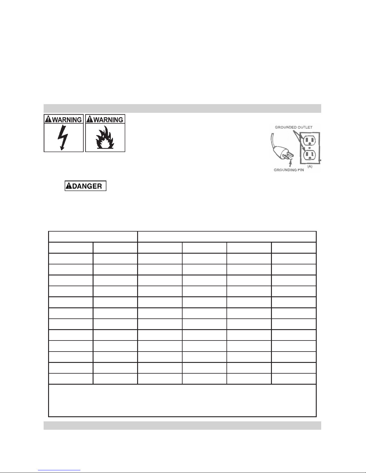
8. GROUNDING AND AC POWER CORD CONNECTIONS
RISK OF ELECTRIC SHOCK OR FIRE.
8.1 This battery charger is for use on a
nominal 120-volt circuit and has a grounded
plug that looks like the plug illustrated. The
charger must be grounded to reduce the risk of
electric shock. The plug must be plugged into
an outlet that is properly installed and grounded in accordance with
all local codes and ordinances. The plug pins must t the receptacle
(outlet). Do not use with an ungrounded system.
8.2 Never alter the AC cord or plug provided – if it does not t the outlet, have
a proper grounded outlet installed by a qualied electrician. An improper connection can
result in a risk of an electric shock or electrocution. NOTE: Pursuant to Canadian
Regulations, use of an adapter plug is not allowed in Canada. Use of an adapter plug in
the United States is not recommended and should not be used.
8.3 Recommended minimum AWG size for extension cord:
AC input rating, amperes* AWG size of cord, Length of cord, feet (m)
At least But less than 25 (7.6) 50 (15.2) 100 (30.5) 150 (45.6)
0 2 18 18 18 16
2 3 18 18 16 14
3 4 18 18 16 14
4 5 18 18 14 12
5 6 18 16 14 12
6 8 18 16 12 10
8 10 18 14 12 10
10 12 16 14 10 8
12 14 16 12 10 8
14 16 16 12 10 8
16 18 14 12 8 8
18 20 14 12 8 6
*If the input rating of a charger is given in watts rather than in amperes, the corresponding
ampere rating is to be determined by dividing the wattage rating by the voltage rating –
for example:
1200 watts/120 volts = 10 amperes
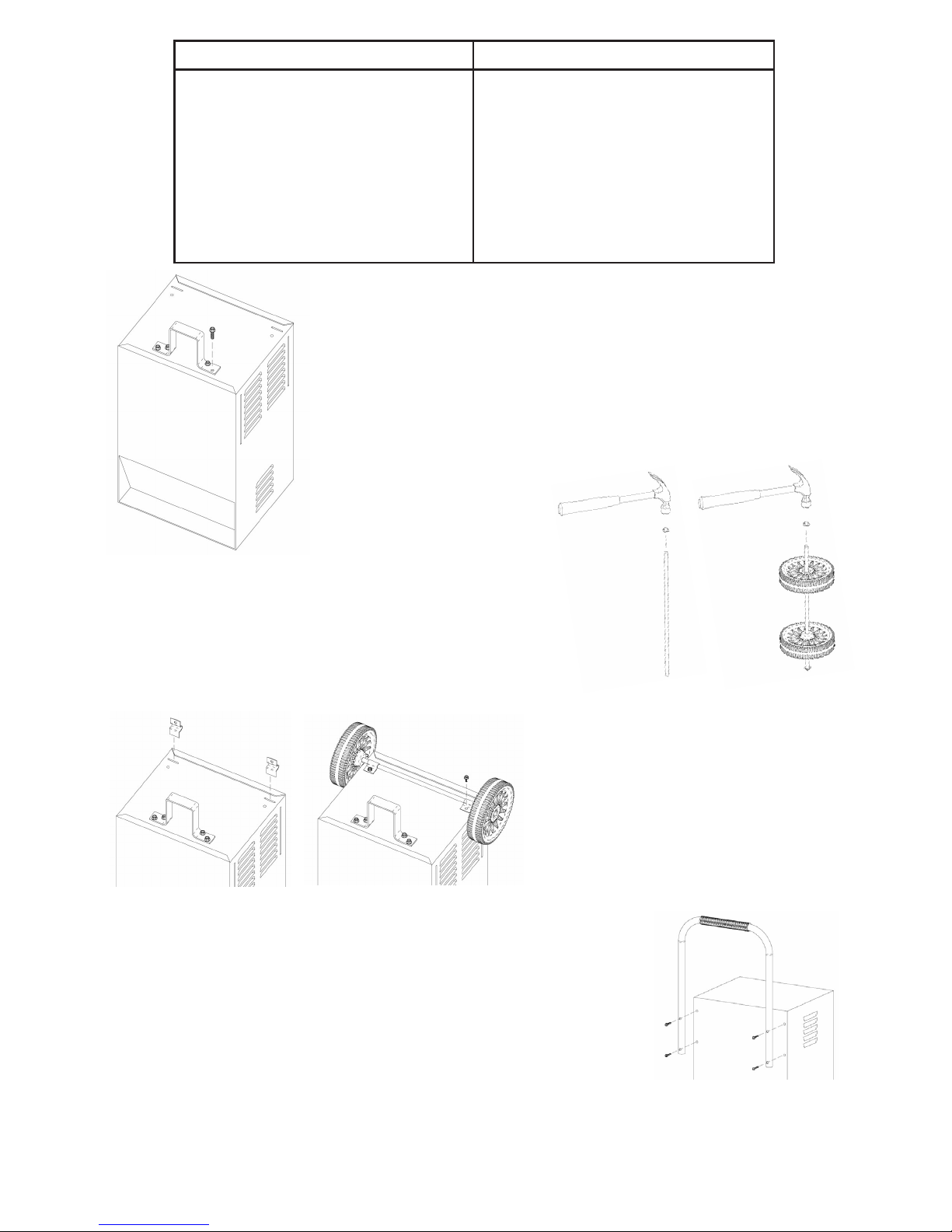
9. ASSEMBLY INSTRUCTIONS
9.1 It is important to fully assemble your charger before use. Remove all cord wraps and
uncoil the cables prior to using the battery charger. Follow these instructions for assembly.
• 6 •
PARTS TOOLS NEEDED
(2) 10-32, thread cutting screws
(4) ¼-20, thread cutting screws
(4) Phillips head sheet metal screws
(2) wheels
(1) axle
(2) axle caps
(2) axle brackets
(1) handle
(1) foot
3/8" wrench (for mounting foot)
5/16" wrench (for mounting wheels)
1/4" wrench (for mounting handle)
hammer
screwdriver (at blade)
screwdriver (Phillips)
Attach the Foot: Remove the charger
from the packing materials and place upside down
on a at surface. Attach the foot and secure it
with the four ¼-20 thread cutting screws provided.
Assemble the Wheels and Axle: Hold the axle upright
on the oor or work surface. Then, using a hammer, tap
one of the axle caps onto the top end of the axle. Be
sure to tap the axle cap on straight. Slide both wheels
onto the axle with the recessed hubs facing out as
shown. Install the second axle cap.
Mount the Axle to the Charger: Place
one end of each bracket into the slot on
the bottom of the charger. Place the axle
assembly under each bracket. Attach
the brackets using the two, 10-32 thread
cutting screws provided.
NOTE: Be careful not to drop the
brackets inside of the charger case.
Attach the Handle: If the charger came with a plastic grip,
slide that onto the handle until it is centered at the top. Turn the
charger right side up onto its foot and wheels. Align the handle
so the screw holes are aligned with the screw holes on the upper
back corners of the charger. Attach the handle using the four
Phillips head screws provided.

• 7 •
10. CONTROL PANEL
Note: Not all controls are available on all models.
Charge Rate Selector Switch
Use the Charge Rate selector switch to select the charge rate or engine starting setting
you require.
• 2A Slow Charge Rate – Intended for charging small batteries such as those
commonly used in garden tractors, snow mobiles and motorcycles.
• 10A, 15A, 20A, 30A Fast and 35A, 40A, 44A, 50A, 60A, 80A Rapid Charge
Rate – Use for charging automotive, marine and deep-cycle batteries. Not intended
for industrial applications.
• 100A, 125A, 180A, 200A, 225A, 300A Engine Start – Provides 100, 125, 180, 200,
225 or 300 amps for cranking an engine with a weak or run down battery. Always use
in combination with a battery.
Timer (Not applicable for Model SE-2352)
• Timer Setting: The timer allows you to set a specied time for charging. After the
timer expires, the charger stops charging your battery. The main function of the
timer is to prevent over charging while allowing a battery time to obtain a satisfactory
charge. To properly set the timer, you must know the size of the battery in ampere
hours or reserve capacity in minutes and the state of charge. It is important that you
determine the appropriate state of charge of your battery as specied in Section 12
and set the timer accordingly.
• Hold: This position defeats the timer function, allowing for continuous operation. Be
sure to monitor the charging progress and stop it when the battery is charged. Not
doing so may cause damage to your battery or may cause other personal property
damage or personal injury.
Ammeter
The Ammeter indicates the amount of current, measured in amps, that is being drawn
by the battery. As a battery takes on a charge, it draws less current from the charger.
Correspondingly, the meter will show less current being drawn by the battery. When the
current stops decreasing, the battery is charged. The start area of the meter indicates a
high rate of current being drawn from the charger. When cranking an engine, the meter
needle will be at the extreme right side of the start area. The 2 amp charge rate may
indicate some activity on the meter, although the meter does not have the resolution to
display this low rate.
• Percent of Charge
The percent of charge scale is intended as a visual aid to help simplify reading the
state of charge. The percent of charge is based on the current drawn by the battery.
For this reason, accuracy will vary with the size and battery type. This means that the
indication for a fully charged large battery may be slightly less than 100%.
Model SE-2352 employs 2 toggle switches:
• Switch #1 – Use this switch to select the 200 Amp Engine Start and the 35 Amp
Charge Rate. Switch #2 must be in the down position (Select Position) when using
Switch #1.
• Switch #2 – Use this switch to select the 2 amp Charge Rate and the OFF position.
Also, use to select use of Switch #1. Note that Switch #1 is only effective when
Switch #2 is set to “Select Position.”
Model SE-3612 employs 3 toggle switches:
• Switch #1 (Furthest left) – Use this switch to select the 12 volt 200 amp engine start
(down) or the 12 volt 40 amp charge (up) position. The center switch (#2) must be in
the (up) position when switch #1 is used.
• Switch #2 (Center) – Use this switch to select use of either switch #1 or switch #3.
Down for switch #3 and up for switch #1.
• Switch #3 (Right) – Use this switch to select the 12 volt 2 amp charge (up) or the
6 volt 100 amp engine start (down). The center switch (#2) must be in the down
position to use switch #3.

• 8 •
Battery Load Tester Switch (Model SE-8050 only)
When testing a battery, use this switch to apply a load to it.
Battery Tester Switch (Models SE-2254 and SE-4022 only)
When testing a battery, use this switch to select between testing a 6 volt battery and
testing a 12 volt battery.
Voltage Selector Switch
Use this switch to set the scale of the voltmeter to either 6 volt and 12 volt DC to match
the battery or batteries being charged. NOTE: This does not change the output voltage
of the charger.
Voltmeter
The voltmeter indicates the voltage at the battery clips. The charger need not be
plugged into an A.C. outlet. The timer should be in the OFF position. Then connect the
charger following the instructions in sections 6 and 7.
11. OPERATING INSTRUCTIONS
This battery charger must be properly assembled in accordance with the
assembly instructions before it is used.
Charging (Model SE-2352)
1. Ensure that all of the charger components are in place and in good working
condition, including the plastic boots on the battery clips. Make sure the electrolyte
(battery liquid) in each cell is at the correct level.
2. Set the charge rate selector switch (switch #2) to the OFF position.
3. Connect the battery, following the precautions listed in Sections 6 and 7.
4. Connect the A.C. power, following the precautions listed in Section 8.
5. Place the charge rate selector switches (switch #1 and #2) in the preferred position.
• For the 2A charge rate, switch #1 is not used and switch #2 should be toggled up.
• For the 35A charge rate, both switches (#1 and #2) should be toggled down.
6. To disconnect the charger, reverse the procedure.
NOTE: This is a manual charger and will overcharge a battery if permitted to operate for
extended periods of time. Monitor the charging often.
Charging (Model SE-3612)
1. Ensure that all of the charger components are in place and in good working
condition, including the plastic boots on the battery clips. Make sure the electrolyte
(battery liquid) in each cell is at the correct level.
2. Set the timer knob to the OFF position.
3. Connect the battery, following the precautions listed in Sections 6 and 7.
4. Connect the A.C. power, following the precautions listed in Section 8.
5. Set the charge rate switch to the desired charge position. See Charge Rate chart.
6. Set the timer from the OFF position to the desired timed charge.
7. To disconnect the charger, reverse the procedure.
NOTE: This is a manual charger and will overcharge a battery if permitted to operate for
extended periods of time. Monitor the charging often.
Charging (Models SE-2254, SE-3000, SE-4020, SE-4022, SE-5025, SE-6030
and SE-8050)
1. Ensure that all of the charger components are in place and in good working
condition, including the plastic boots on the battery clips. Make sure the electrolyte
(battery liquid) in each cell is at the correct level.
2. Connect the battery following the precautions listed in sections 6 and 7.
3. Select the appropriate settings for your battery.
4. Connect the A.C. power following the precautions listed in section 8.
5. Turn the charger on. (If necessary)

• 9 •
Using the Engine Start feature
Your battery charger can be used to jumpstart your car if the battery is low. Follow these
instructions on how to use the ENGINE START feature.
Follow all safety instructions and precautions for charging your battery.
Wear complete eye protection and clothing protection. Charge your battery in a wellventilated area.
Using the ENGINE START feature WITHOUT a battery installed in the
vehicle could cause damage to the vehicle’s electrical system. NOTE: If you have
charged the battery and it still will not start your car, do not use the engine start feature,
or it could damage the vehicle’s electrical system.
1. Set the charge rate switch and the timer to the OFF position.
2. With the charger unplugged from the A.C. outlet, connect the charger to the battery
following the instructions given in Section 6 (FOLLOW THESE STEPS WHEN THE
BATTERY IS INSTALLED IN A VEHICLE).
3. Plug the charger A.C. power cord into the A.C. outlet, and then move the timer switch
from OFF to the HOLD position.
4. With the charger plugged in and connected to the battery of the vehicle, set the
charge rate selector switch to the engine start position.
5. Crank the engine until it starts or 5 seconds pass. If the engine does not start, wait 3
minutes before cranking again. This allows the charger and battery to cool down.
NOTE: During extremely cold weather, or if the battery is under 2 volts, charge the
battery for 5 minutes before cranking the engine.
6. If the engine fails to start, charge the battery for 5 more minutes before attempting to
crank the engine again.
7. After the engine starts, move the charge rate selector switch and timer to the off
position and unplug the A.C. power cord before disconnecting the battery clips from
the vehicle.
8. Clean and store the charger in a dry location.
NOTE: If the engine does turn over but never starts, there is not a problem with the
starting system; there is a problem somewhere else with the vehicle. STOP cranking the
engine until the other problem has been diagnosed and corrected.
Using the Battery Voltage Tester (Models SE-2254 and SE-4022 only)
1. Set the Voltage Selector switch to the correct setting (6V or 12V) to match the battery
to be tested.
2. Set the timer to the OFF position.
3. Connect the battery to the charger as specied in sections 6 and 7. The charger
does not need to be plugged into an A.C. outlet.
4. Read the voltmeter.
Keep in mind that this reading is only a battery voltage reading, a false charge may
mislead you. We suggest that you turn on the headlights for a couple of minutes and
then wait a couple of minutes after you have turned them off before reading the meter.
Then, follow the convenient color code shown on the meter.
Using the Battery Load Tester (Model SE-8050 only)
1. Set the Voltage Selector switch to the correct setting (6V or 12V) to match the battery
to be tested.
2. Set the timer to the OFF position.
3. Connect the battery to the charger as specied in sections 6 and 7. The charger
does not need to be plugged into an A.C. outlet.
4. Press the Battery Load Test switch to LOAD ON for 10 seconds and read the
voltmeter.
Green – Indicates the battery capacity is OK. The battery may or may not be fully
charged. Check the specic gravity to determine the state of charge. If the specic
gravity shows less than a full charge, check for an electrical drain on the battery or for
possible charging system problems. Recharge the battery to full charge.

• 10 •
Yellow or Red, but the needle remains steady – Indicates that the battery capacity is
not satisfactory. The battery may be either defective or not fully charged. Check the
specic gravity of the battery to see which condition exists. If charging does not bring the
battery up to a full charge, the battery should be replaced.
Yellow or Red, but the needle continues to fall – Indicates the battery may be defective
or rundown. Release the load switch and note the voltmeter reaction. Voltage recovery
into the green or above within seconds indicates a defective battery. A slow recovery
indicates a rundown condition. For best results, check the specic gravity of the battery.
General Charging Notes
Fan: It is normal for the fan to be on all the time. Keep the area near the charger clear of
obstructions to allow the fan to operate efciently.
12. CALCULATING CHARGE TIME
Battery Percent and Charge Time: This charger adjusts the charging time in order to
charge the battery completely, efciently and safely. The microprocessor automatically
performs the necessary functions. This section includes guidelines that can be used to
estimate charging times.
The Hydrometer or Electronic Method
To nd the time needed to fully charge your battery, determine the battery’s charge level
with a hydrometer or electronic Percent-of-Charge Tester. The following table will help
you convert hydrometer readings to percent of charge values.
SPECIFIC GRAVITY
PERCENT OF
CHARGE
PERCENT OF
CHARGE NEEDED
1.265 100% 0%
1.225 75% 25%
1.155 25% 75%
1.120 0% 100%
When you know the percent of charge and the Amp Hour (AH) rating of your battery, you
can calculate the approximate time needed to bring your battery to a full charge.
To convert Reserve Capacity to Amp Hours, divide Reserve Capacity by 2, and add 16:
Example:
Amp Hour Rating = Reserve Capacity + 16
2
NOTE: The Reserve Capacity can be obtained from the battery specication sheet or
the owner’s manual.
To calculate the time needed for a charge:
1. Find the percent of charge needed. (A battery at 50 percent charge that will be
charged to 100 percent needs another 50 percent (.50)).
2. Multiply the Amp Hour Rating by the charge needed (.50) and divide by the charge
rate setting.
3. Multiply the results by 1.25 and you will have the total time needed, in hours, to bring
the battery to full charge.
4. Add an additional hour for a deep-cycle battery.
Example:
Amp Hour Rating x % of charge needed x 1.25 = hours of charge
Charge Rate Setting
100 (AH Rating) x 0.50 (charge needed) x 1.25 = 3.125 hours
20 (Charge Rate Setting)
100 x 0.50 x 1.25 = 3.125
20
You would need to charge your 100-Ampere Hour Battery for a little more than 3 hours
at the 20-Amp charge rate using the above example.
 Loading...