

Model SE-1555A
OWNER’S MANUAL
00-99-000810/0608
Volt: 12
Amps: 2, 20, 55, 150
Automatic/Manual Battery Charger


• 1 •
IMPORTANT SAFETY INSTRUCTIONS1.
SAVE THESE INSTRUCTIONS – This manual contains important safety 1.1
and operating instructions for battery charger Model SE-1555A.
Do not expose charger to rain or snow.1.2
Use of an attachment not recommended or sold by the battery charger 1.3
manufacturer may result in a risk of re, electric shock, or injury to persons.
To reduce risk of damage to electric plug and cord, pull by plug rather than 1.4
cord when disconnecting charger.
An extension cord should not be used unless absolutely necessary. Use of 1.5
improper extension cord could result in a risk of re and electric shock. If
an extension cord must be used, make sure:
That pins on plug of extension cord are the same number, size, and •
shape as those of plug on charger;
That extension cord is properly wired and in good electrical condition and;•
That wire size is large enough for AC ampere rating of charger as speci-•
ed in Table 8.3.
Do not operate charger with damaged cord or plug; take to a qualied 1.6
service person. (Call customer service at: 800-621-5485.)
Do not operate charger if it has received a sharp blow, been dropped, or 1.7
otherwise damaged in any way; take it to a qualied serviceman. (Call
customer service at: 800-621-5485.)
Do not disassemble charger; take it to a qualied serviceman when 1.8
service or repair is required. Incorrect reassembly may result in a risk of
electric shock or re. (Call customer service at: 800-621-5485.)
To reduce risk of electric shock, unplug charger from outlet before attempt-1.9
ing any maintenance or cleaning. Turning off controls will not reduce this
risk.
WARNING – RISK OF EXPLOSIVE GASES.
WORKING IN VICINITY OF A LEAD-ACID BATTERY IS DANGEROUS.
BATTERIES GENERATE EXPLOSIVE GASES DURING NORMAL
BATTERY OPERATION. FOR THIS REASON, IT IS OF UTMOST
IMPORTANCE THAT YOU FOLLOW THE INSTRUCTIONS EACH TIME
YOU USE THE CHARGER.
TO REDUCE RISK OF BATTERY EXPLOSION, FOLLOW THESE
INSTRUCTIONS AND THOSE PUBLISHED BY BATTERY MANUFACTURER AND MANUFACTURER OF ANY EqUIPMENT YOU INTEND TO
USE IN VICINITY OF BATTERY. REVIEW CAUTIONARY MARKING ON
THESE PRODUCTS AND ON ENGINE.
IMPORTANT: READ AND SAVE THIS SAFETY AND INSTRUCTION MANUAL.

• 2 •
PERSONAL PRECAUTIONS2.
Consider having someone close enough by to come to your aid when you 2.1
work near a lead-acid battery.
Have plenty of fresh water and soap nearby in case battery acid contacts 2.2
skin, clothing, or eyes.
Wear complete eye protection and clothing protection. Avoid touching 2.3
eyes while working near battery.
If battery acid contacts skin or clothing, wash immediately with soap and 2.4
water. If acid enters eye, immediately ood eye with running cold water for
at least 10 minutes and get medical attention immediately.
NEVER smoke or allow a spark or ame in vicinity of battery or engine.2.5
Be extra cautious to reduce risk of dropping a metal tool onto battery. It 2.6
might spark or short-circuit battery or other electrical part that may cause
explosion.
Remove personal metal items such as rings, bracelets, necklaces, and 2.7
watches when working with a lead-acid battery. A lead-acid battery can
produce a short-circuit current high enough to weld a ring or the like to
metal, causing a severe burn.
Use charger for charging a LEAD-ACID battery only. It is not intended to 2.8
supply power to a low voltage electrical system other than in a starter-motor application. Do not use battery charger for charging dry-cell batteries
that are commonly used with home appliances. These batteries may burst
and cause injury to persons and damage to property.
NEVER charge a frozen battery.2.9
PREPARING TO CHARGE3.
If necessary to remove battery from vehicle to charge, always remove 3.1
grounded terminal from battery rst. Make sure all accessories in the
vehicle are off, so as not to cause an arc.
Be sure area around battery is well ventilated while battery is being 3.2
charged.
Clean battery terminals. Be careful to keep corrosion from coming in con-3.3
tact with eyes.
Add distilled water in each cell until battery acid reaches level specied by 3.4
battery manufacturer. Do not overll. For a battery without removable cell
caps, such as valve regulated lead acid batteries, carefully follow manu-
facturer’s recharging instructions.
Study all battery manufacturer’s specic precautions while charging and 3.5
recommended rates of charge.
Determine voltage of battery by referring to vehicle owner’s manual and 3.6
make sure that output voltage selector switch is set at correct voltage. If
charger has adjustable charge rate, charge battery initially at lowest rate.

• 3 •
CHARGER LOCATION4.
Locate charger as far away from battery as DC cables permit.4.1
Never place charger directly above battery being charged; gases from bat-4.2
tery will corrode and damage charger.
Never allow battery acid to drip on charger when reading electrolyte spe-4.3
cic gravity or lling battery.
Do not operate charger in a closed-in area or restrict ventilation in any 4.4
way.
Do not set a battery on top of charger.4.5
DC CONNECTION PRECAUTIONS5.
Connect and disconnect DC output clips only after setting any charger 5.1
switches to “off” position and removing AC cord from electric outlet. Never
allow clips to touch each other.
Attach clips to battery and chassis, as indicated in 6.5, 6.6, and 7.2 5.2
through 7.4.
FOLLOW THESE STEPS WHEN BATTERY IS INSTALLED IN 6.
VEHICLE.
A SPARK NEAR BATTERY MAY CAUSE BATTERY EXPLOSION. TO
REDUCE RISK OF A SPARK NEAR BATTERY:
Position AC and DC cords to reduce risk of damage by hood, door, or 6.1
moving engine part.
Stay clear of fan blades, belts, pulleys, and other parts that can cause 6.2
injury to persons.
Check polarity of battery posts. POSITIVE (POS, P, +) battery post usually 6.3
has larger diameter than NEGATIVE (NEG, N,–) post.
Determine which post of battery is grounded (connected) to the chassis. 6.4
If negative post is grounded to chassis (as in most vehicles), see (6.5). If
positive post is grounded to the chassis, see (6.6).
For negative-grounded vehicle, connect POSITIVE (RED) clip from battery 6.5
charger to POSITIVE (POS, P, +) ungrounded post of battery. Connect
NEGATIVE (BLACK) clip to vehicle chassis or engine block away from
battery. Do not connect clip to carburetor, fuel lines, or sheet-metal body
parts. Connect to a heavy gauge metal part of the frame or engine block.
For positive-grounded vehicle, connect NEGATIVE (BLACK) clip from bat-6.6
tery charger to NEGATIVE (NEG, N, –) ungrounded post of battery. Con-
nect POSITIVE (RED) clip to vehicle chassis or engine block away from
battery. Do not connect clip to carburetor, fuel lines, or sheet-metal body
parts. Connect to a heavy gauge metal part of the frame or engine block.

• 4 •
When disconnecting charger, turn switches to off, disconnect AC cord, 6.7
remove clip from vehicle chassis, and then remove clip from battery termi-
nal.
See OPERATING INSTRUCTIONS for length of charge information.6.8
FOLLOW THESE STEPS WHEN BATTERY IS OUTSIDE VEHICLE. 7.
A SPARK NEAR THE BATTERY MAY CAUSE BATTERY EXPLOSION.
TO REDUCE RISK OF A SPARK NEAR BATTERY:
Check polarity of battery posts. POSITIVE (POS, P, +) battery post usually 7.1
has a larger diameter than NEGATIVE (NEG, N, –) post.
Attach at least a 24-inch-long 6-gauge (AWG) insulated battery cable to 7.2
NEGATIVE (NEG, N, –) battery post.
Connect POSITIVE (RED) charger clip to POSITIVE (POS, P, +) post of 7.3
battery.
Position yourself and free end of cable as far away from battery as pos-7.4
sible – then connect NEGATIVE (BLACK) charger clip to free end of cable.
Do not face battery when making nal connection.7.5
When disconnecting charger, always do so in reverse sequence of con-7.6
necting procedure and break rst connection while as far away from bat-
tery as practical.
A marine (boat) battery must be removed and charged on shore. To 7.7
charge it onboard requires equipment specially designed for marine use.

• 5 •
BATTERY CHARGING - AC CONNECTIONS8.
For all grounded cord-connected battery chargers:8.1
GROUNDING AND AC POWER CORD CONNECTION •
INSTRUCTIONS – Charger should be grounded to reduce risk of electric
shock. Charger is equipped with an electric cord having an equipmentgrounding conductor and a grounding plug. The plug must be plugged
into an outlet that is properly installed and grounded in accordance with
all local codes and ordinances.
DANGER – Never alter AC cord or plug provided – if it will not t outlet,
have proper outlet installed by a qualied electrician. Improper connection can result in a risk of an electric shock.
For grounded, cord-connected battery chargers with an input rating 8.2
less than 15 amperes and intended for use on a nominal 120-volt
circuit:
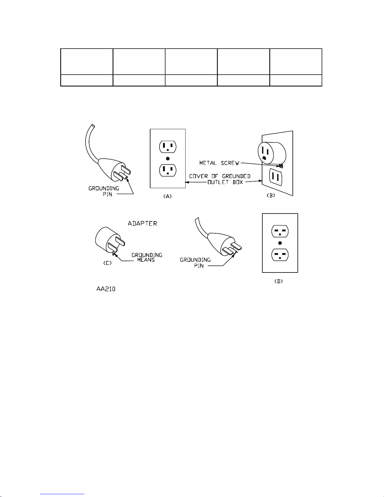
This battery charger is for use on a nominal 120-volt circuit, and has a •
grounding plug that looks like the plug illustrated in sketch A in Figure
8.4. A temporary adapter, which looks like the adapter illustrated in
sketches B and C, may be used to connect this plug to a two-pole recep-
tacle as shown in sketch B if a properly grounded outlet is not available.
The temporary adapter should be used only until a properly grounded
outlet can be installed by a qualied electrician.
DANGER – Before using adapter as illustrated, be certain that center
screw of outlet plate is grounded. The green-colored rigid ear or lug ex
tending from adapter must be connected to a properly grounded outlet–
make certain it is grounded. If necessary, replace original outlet cover
plate screw with a longer screw that will secure adapter ear or lug to
outlet cover plate and make ground connection to grounded outlet.
• 6 •
Recommended minimum awg size for extension cords for this bat-8.3
tery charger.
Length of
Cord
feet (m)
25
(7.6)
50
(15.2)
100
(30.5)
150
(45.6)
Gauge 16 14 10 8
8.4
Grounding Methods
• 7 •
ASSEMBLY INSTRUCTIONS9.
It is important to fully assemble your charger before use. Follow these
instructions for easy assembly.
PARTS TOOLS NEEDED
Two, 10 -32 thread cutting
screws
3/8" wrench (for mounting
foot)
Four, 1/4-20 thread cutting
screws
5/16" wrench (for wheels)
Two wheels Hammer
One axle
Screwdriver (for handle
assembly)
Two axle caps
Two axle brackets
One handle
One handle grip
One mounting foot
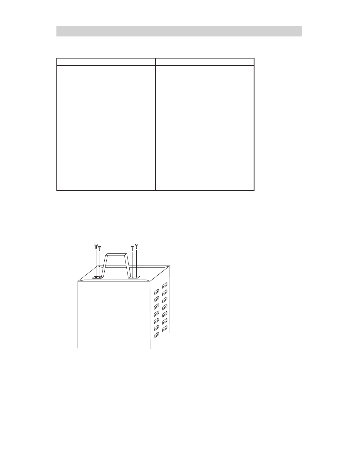
Attach Foot:9.1
Remove charger from packing materials and place charger top down. At-
tach mounting foot and secure with the four, 1/4-20 thread cutting screws
provided.
• 8 •
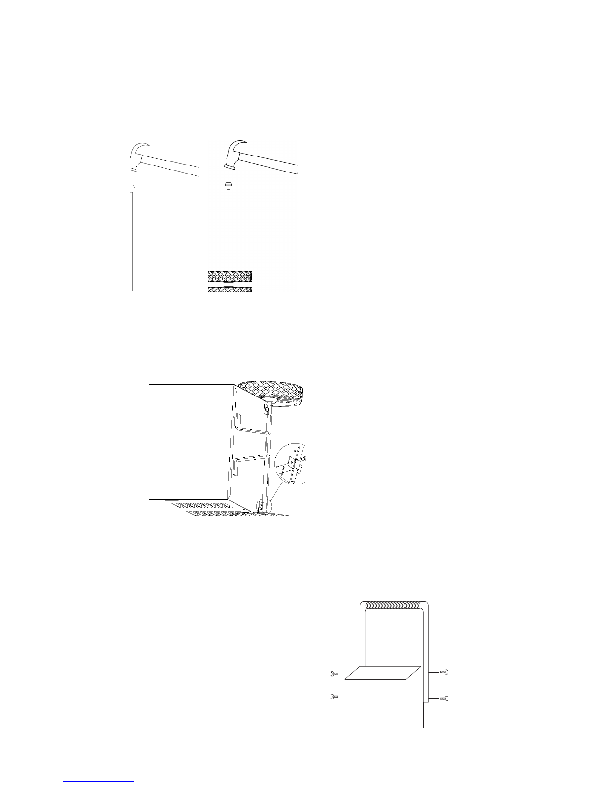
Axle Assembly:9.2
Hold axle upright on oor or work surface. Then, using a hammer, tap one
of the axle caps onto the top end of the axle. Be sure to tap the hub on
straight. Slide both wheels onto the axle with the hubs facing inward. Tap
the other axle cap onto the opposite end of the axle and place the axle
assembly onto the bottom of the charger.
Axle Assembly:9.3
Place the charger on its side. Place one end of each bracket into slot,
then place the axle assembly under each bracket. Fasten the other side of
each bracket using the two, 10-32 thread cutting screws provided.
Handle:9.4
Turn the charger right side up onto its foot and wheels. Verify grip and
handle clamp rod are installed on the handle. Remove the two top screws
from each side of the charger. Align the handle so the screw holes are
aligned with the screw holes on each side of the wheel charger. Attach
handle using the same screws.
• 9 •
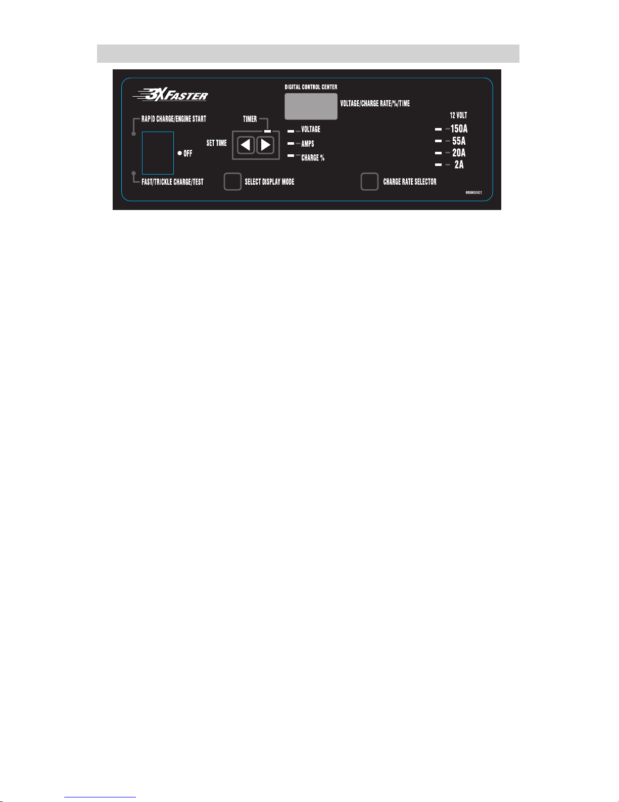
OPERATING INSTRUCTIONS10.
SELECT CHARGE RATE10.1
The CHARGE RATE SELECTOR allows you to select the correct amp
draw rate to match your charging needs. Read the following operating
instructions for making the proper settings for charging a battery.
When you rst start charging a battery, the amp reading will be high. As
the battery becomes charged, the reading will decrease.
To determine the amount of amps being drawn by the battery:
Press the Select Display Mode button until the AMPS LED lights.a.
When the 55A setting is used, the charger switches between 55A boost b.
mode and 10A mode. You should use a lower charge setting if the volt-
age reading is “OL” or is reading higher than 14.2 Volts for more than 3
minutes and you are not in automatic mode.
When charging at 20 amps, the display should show 20 amps for c.
a discharged battery and 7-8 amps for a fully charged battery. You
should stop charging the battery at this time if you are using the
manual mode.
At the 2 amp charge rate, little or no display change will occur.d.
TIMER10.2
The timer is designed to allow the battery to be charged for a designated
amount of time. To accurately charge your battery, you must know the size
of the battery in ampere hours or reserve capacity in units, as well as the
state of charge. Since this information is not known by the charger, the
timer limit is set at 2.25 hours to prevent the battery from overcharging to
a point where it can be severely damaged. If you do not know the charge
state of your battery, set the timer at one hour or less, or use the automatic setting.
TO SET THE TIMER10.3
Press the a. symbol for less time and the symbol for more time.
The Timer LED will light and digital display will show the time in min-b.
utes.
To turn the timer off, press the c. symbol until the digital display reads
OFF.
 Loading...