

Page 1
OWNER’S MANUAL
TM
ELECTRONIC
BATTERY CHARGER
2
amp
SLOW
CHARGE
100
12
30
amp
FAST
CHARGE
amp
ENGINE
START
Model SC-10030A
For 6 and 12-Volt Batteries
®
Fully Automatic
Microprocessor Controlled
Battery Charger with
Engine Starter plus
Battery Tester and
Alternator Tester
00-99-000828/0408
Page 2

Page 3

IMPORTANT: READ AND SAVE THIS SAFETY AND INSTRUCTION MANUAL.
IMPORTANT SAFETY INSTRUCTIONS1.
SAVE THESE INSTRUCTIONS – This manual contains important safety 1.1
and operating instructions for battery charger Model SC-10030A.
Do not expose charger to rain or snow.1.2
Use of an attachment not recommended or sold by the battery charger 1.3
manufacturer may result in a risk of re, electric shock, or injury to persons.
To reduce risk of damage to electric plug and cord, pull by plug rather than 1.4
cord when disconnecting charger.
An extension cord should not be used unless absolutely necessary. Use of 1.5
improper extension cord could result in a risk of re and electric shock. If
an extension cord must be used, make sure:
That pins on plug of extension cord are the same number, size, and •
shape as those of plug on charger;
That extension cord is properly wired and in good electrical condition and;•
That wire size is large enough for AC ampere rating of charger as speci-•
ed in Table 9.1.
Do not operate charger with damaged cord or plug – replace the cord or 1.6
plug immediately. (Call customer service at: 800-621-5485.)
Do not operate charger if it has received a sharp blow, been dropped, or 1.7
otherwise damaged in any way; take it to a qualied serviceman. (Call
customer service at: 800-621-5485.)
Do not disassemble charger; take it to a qualied serviceman when 1.8
service or repair is required. Incorrect reassembly may result in a risk of
electric shock or re. (Call customer service at: 800-621-5485.)
To reduce risk of electric shock, unplug charger from outlet before attempt-1.9
ing any maintenance or cleaning. Turning off controls will not reduce this
risk.
WARNING – RISK OF EXPLOSIVE GASES.
WORKING IN VICINITY OF A LEAD-ACID BATTERY IS DANGEROUS.
BATTERIES GENERATE EXPLOSIVE GASES DURING NORMAL
BATTERY OPERATION. FOR THIS REASON, IT IS OF UTMOST
IMPORTANCE THAT YOU FOLLOW THE INSTRUCTIONS EACH TIME
YOU USE THE CHARGER.
TO REDUCE RISK OF BATTERY EXPLOSION, FOLLOW THESE
INSTRUCTIONS AND THOSE PUBLISHED BY BATTERY MANUFACTURER AND MANUFACTURER OF ANY EQUIPMENT YOU INTEND TO
USE IN VICINITY OF BATTERY. REVIEW CAUTIONARY MARKING ON
THESE PRODUCTS AND ON ENGINE.
• 1 •
Page 4

PERSONAL PRECAUTIONS2.
Consider having someone close enough by to come to your aid when you 2.1
work near a lead-acid battery.
Have plenty of fresh water and soap nearby in case battery acid contacts 2.2
skin, clothing, or eyes.
Wear complete eye protection and clothing protection. Avoid touching 2.3
eyes while working near battery.
If battery acid contacts skin or clothing, wash immediately with soap and 2.4
water. If acid enters eye, immediately ood eye with running cold water for
at least 10 minutes and get medical attention immediately.
NEVER smoke or allow a spark or ame in vicinity of battery or engine.2.5
Be extra cautious to reduce risk of dropping a metal tool onto battery. It 2.6
might spark or short-circuit battery or other electrical part that may cause
explosion.
Remove personal metal items such as rings, bracelets, necklaces, and 2.7
watches when working with a lead-acid battery. A lead-acid battery can
produce a short-circuit current high enough to weld a ring or the like to
metal, causing a severe burn.
Use charger for charging a LEAD-ACID battery only. It is not intended to 2.8
supply power to a low voltage electrical system other than in a starter-motor application. Do not use battery charger for charging dry-cell batteries
that are commonly used with home appliances. These batteries may burst
and cause injury to persons and damage to property.
NEVER charge a frozen battery.2.9
PREPARING TO CHARGE3.
If necessary to remove battery from vehicle to charge, always remove 3.1
grounded terminal from battery rst. Make sure all accessories in the
vehicle are off, so as not to cause an arc.
Be sure area around battery is well ventilated while battery is being 3.2
charged.
Clean battery terminals. Be careful to keep corrosion from coming in con-3.3
tact with eyes.
Add distilled water in each cell until battery acid reaches level specied by 3.4
battery manufacturer. Do not overll. For a battery without removable cell
caps, such as valve regulated lead acid batteries, carefully follow manu-
facturer’s recharging instructions.
Study all battery manufacturer’s specic precautions while charging and 3.5
recommended rates of charge.
Determine voltage of battery by referring to vehicle owner’s manual and 3.6
make sure that output voltage selector switch is set at correct voltage. If
charger has adjustable charge rate, charge battery initially at lowest rate.
• 2 •
Page 5

CHARGER LOCATION4.
Locate charger as far away from battery as DC cables permit.4.1
Never place charger directly above battery being charged; gases from bat-4.2
tery will corrode and damage charger.
Never allow battery acid to drip on charger when reading electrolyte spe-4.3
cic gravity or lling battery.
Do not operate charger in a closed-in area or restrict ventilation in any 4.4
way.
Do not set a battery on top of charger.4.5
DC CONNECTION PRECAUTIONS5.
Connect and disconnect DC output clips only after setting any charger 5.1
switches to “off” position and removing AC cord from electric outlet. Never
allow clips to touch each other.
Attach clips to battery and chassis, as indicated in 6.5, 6.6, and 7.2 5.2
through 7.4.
FOLLOW THESE STEPS WHEN BATTERY IS INSTALLED IN 6.
VEHICLE.
A SPARK NEAR BATTERY MAY CAUSE BATTERY EXPLOSION. TO
REDUCE RISK OF A SPARK NEAR BATTERY:
Position AC and DC cords to reduce risk of damage by hood, door, or 6.1
moving engine part.
Stay clear of fan blades, belts, pulleys, and other parts that can cause 6.2
injury to persons.
Check polarity of battery posts. POSITIVE (POS, P, +) battery post usually 6.3
has larger diameter than NEGATIVE (NEG, N,–) post.
Determine which post of battery is grounded (connected) to the chassis. 6.4
If negative post is grounded to chassis (as in most vehicles), see (6.5). If
positive post is grounded to the chassis, see (6.6).
For negative-grounded vehicle, connect POSITIVE (RED) clip from battery 6.5
charger to POSITIVE (POS, P, +) ungrounded post of battery. Connect
NEGATIVE (BLACK) clip to vehicle chassis or engine block away from
battery. Do not connect clip to carburetor, fuel lines, or sheet-metal body
parts. Connect to a heavy gauge metal part of the frame or engine block.
For positive-grounded vehicle, connect NEGATIVE (BLACK) clip from bat-6.6
tery charger to NEGATIVE (NEG, N, –) ungrounded post of battery. Con-
nect POSITIVE (RED) clip to vehicle chassis or engine block away from
battery. Do not connect clip to carburetor, fuel lines, or sheet-metal body
parts. Connect to a heavy gauge metal part of the frame or engine block.
• 3 •
Page 6

When disconnecting charger, turn switches to off, disconnect AC cord, 6.7
remove clip from vehicle chassis, and then remove clip from battery termi-
nal.
See OPERATING INSTRUCTIONS for length of charge information.6.8
FOLLOW THESE STEPS WHEN BATTERY IS OUTSIDE VEHICLE. 7.
A SPARK NEAR THE BATTERY MAY CAUSE BATTERY EXPLOSION.
TO REDUCE RISK OF A SPARK NEAR BATTERY:
Check polarity of battery posts. POSITIVE (POS, P, +) battery post usually 7.1
has a larger diameter than NEGATIVE (NEG, N, –) post.
Attach at least a 24-inch-long 6-gauge (AWG) insulated battery cable to 7.2
NEGATIVE (NEG, N, –) battery post.
Connect POSITIVE (RED) charger clip to POSITIVE (POS, P, +) post of 7.3
battery.
Position yourself and free end of cable as far away from battery as pos-7.4
sible – then connect NEGATIVE (BLACK) charger clip to free end of cable.
Do not face battery when making nal connection.7.5
When disconnecting charger, always do so in reverse sequence of con-7.6
necting procedure and break rst connection while as far away from bat-
tery as practical.
A marine (boat) battery must be removed and charged on shore. To 7.7
charge it onboard requires equipment specially designed for marine use.
AC CONNECTIONS8.
This battery charger is for use on a nominal 120-volt circuit.8.1
DANGER – Never alter AC cord or plug provided – if it will not t outlet,
have proper outlet installed by a qualied electrician. Improper connection can result in a risk of an electric shock.
• 4 •
Page 7

RECOMMENDED MINIMUM AWG SIZE FOR EXTENSION CORDS 9.
25 50 100 150
(7.6) (15.2) (30.5) (45.6)
0 2 18 18 18 16
2 3 18 18 16 14
3 4 18 18 16 14
4 5 18 18 14 12
5 6 18 16 14 12
6 8 18 16 12 10
8 10 18 14 12 10
10 12 16 14 10 8
12 14 16 12 10 8
14 16 16 12 10 8
16 18 14 12 8 8
18 20 14 12 8 6
a
If the input rating of a charger is given in watts rather than in
amperes, the corresponding ampere rating is to be determined
by dividing the wattage rating by the voltage rating ± for
example:
1250 watts/125 volts = 10 amperes
Length of cord, feet (m)
AWG size of cord
AC input rating,
amperes
a
But less
than
At least
FOR BATTERY CHARGERS
9.1
• 5 •
Page 8

ASSEMBLY INSTRUCTIONS10.
Included with your battery charger are two cord wrap cleats for storage of 10.1
the clamp cables.
To install, align the two tabs to correspond with the two receptacles and 10.2
push until you hear a snap.
Wrap clamp cables after unplugging the power cord from the AC wall 10.3
outlet and store your charger in a dry location.
USING ENGINE START11.
Your battery charger can be used to jump start your vehicle if the battery is
low. Follow these instructions on how to use the
ENGINE START feature.
IMPORTANT: Follow all safety instructions and precautions when charg-
ing your battery. Wear complete eye protection and clothing protection.
Charge your battery in a well-ventilated area.
IMPORTANT: Using the ENGINE START feature WITHOUT a battery
installed in the vehicle could cause damage to the vehicle’s electrical
system.
With the charger plugged in and connected to battery and chasis, press 11.1
the BATTERY SIZE button until the ENGINE START LED is lit. The display
mode will be automatically set to VOLTAGE.
Crank the engine for no more than 5 seconds. If engine does not start, 11.2
wait 3 minutes before cranking again.
After the engine starts, unplug the power cord before disconnecting the 11.3
output clamps.
Clean and store the charger in a dry location.11.4
NOTE:11.5 During the starting sequence listed above, the charger is set to
one of three states.
Wait for cranking1. - The charger waits until the engine is actually being
cranked before delivering 100 amps for engine start. The charger
delivers charge at a rate of up to 12 amps while waiting and will reset
if the engine is not cranked within 15 minutes. (If the charger resets, it
sets itself for SMALL BATTERY SIZE and 12V AGM BATTERY TYPE.)
While waiting for cranking, the digital display shows the battery voltage
(it can’t be set to percent.)
Cranking 2. - When cranking is detected, the charger will automatically
deliver up to its maximum output (at least 100A) as required by the
starting system for up to 5 seconds or until the engine cranking stops.
The digital display shows a countdown of the remaining crank time in
seconds. It starts at 5 and counts down to 0.
Cool Down3. - After cranking, the charger enters a mandatory 3-minute
(180 second) cool down state. During this period, no settings can be
• 6 •
Page 9

changed. The buttons are ignored. The digital display indicates the
remaining cool down time in seconds. It starts at 180 and counts down
to 0. The ENGINE START LED blinks once every second. During the
cool down period, no current is delivered to the battery. After 3 minutes,
the ENGINE START LED will stop blinking and will light continuously,
indicating that another crank cycle can be started. The digital display
will change from displaying the countdown back to displaying the
battery voltage. The CHARGING LED will then be lit.
ENGINE STARTING NOTES:
If the battery is disconnected during the cool down period, the charger •
will reset.
OPERATING INSTRUCTIONS12.
OVERVIEW: Using this battery charger is very simple. First, connect
the battery and AC power. Then select the appropriate BATTERY TYPE
and BATTERY SIZE for your battery. The charger will then do everything
automatically. This section explains a few details.
CHARGING: 12.1 If the charger does not detect a properly connected battery,
the CONNECTED LED will not light. Charging will not begin unless the
CONNECTED LED is on. When charging begins, the CHARGING LED will
be lit.
AUTOMATIC SHUT OFF:12.2 When the SMALL BATTERY or MEDIUM TO
LARGE BATTERY SIZE is selected, the charger is set to perform an automatic charge. When an automatic charge is performed, the charger stops
charging automatically after the battery is charged.
ABORTED CHARGE: 12.3 If charging can’t be completed normally, charging
will be aborted. When charging is aborted, the charger’s output is shut off
and the digital display blinks on and off. In that state, the charger ignores
all buttons. To reset from after an aborted charge, either disconnect the
battery or unplug the charger.
DESULFATION MODE:12.4 If a battery is left discharged for an extended
period, it could become sulfated and not accept a normal charge. If the
charger detects a sulfated battery, the charger will switch to a special
mode of operation designed for such batteries. Activation of the special
desulfation mode is indicated by blinking the CHARGING LED. If suc-
cessful, normal charging will resume after the battery is desulfated. The
CHARGING LED will then stop blinking and light continuously. Desulfation
• 7 •
Page 10

could take up to 10 hours. If desulfation fails, charging will be aborted and
DIGITAL DISPLAY
the digital display will blink.
COMPLETION OF CHARGING: 12.5
12V or 6V Standard Battery: • Charge completion is indicated by the
CHARGED (green) LED; when lit, the charger has stopped charging and
switched to the Maintain Mode of operation.
12V AGM OR GEL CELL BATTERY:• The CHARGED LED comes on
when the battery is charged enough for normal use. After charging is
complete, the CHARGED LED will be on and the voltage will be less than
14V.
MAINTAIN MODE12.6 : When the CHARGED (green) LED is lit, the charger
has started Maintain Mode. This mode of operation is also known as FloatMode Monitoring. In this mode, the charger keeps the battery fully charged
by delivering a small amount of current, when necessary. The voltage is
maintained at a level determined by the BATTERY TYPE selected.
NOTE: For 12V AGM and 12V GEL CELL battery types, the CHARGED
LED might be lit before the maintain mode is started.
GENERAL CHARGING NOTES:12.7 The charger is designed to control its
cooling fan for efcient operation, but the fan might run continuously when
maintaining a fully charged battery. The fan does not run in Tester Mode.
If the charge mode is changed after charging has started (by pressing the
BATTERY SIZE or BATTERY TYPE button), the charging process will be
restarted.
The voltage displayed during charging will usually be higher than the battery’s resting voltage.
The voltage displayed during charging is the battery voltage, not the RMS
charging voltage.
CHARGER CONTROLS13.
• 8 •
Page 11

DIGITAL DISPLAY BUTTON 13.1
Use this button to set the function of the digital display to one of the follow-
ing:
BATTERY %:• The digital display shows an estimate of the percent of
charge of the battery connected to the charger battery clamps.
VOLTAGE: • The digital display shows the voltage at the charger battery
clamps in DC volts.
ALTERNATOR %: • The digital display shows an estimated percentage of
the output of the vehicle charging system connected to the charger battery clamps as compared to a properly functioning system.
BATTERY TYPE BUTTON 13.2
Use this button to set the type of battery to be charged to one of the following.
12V STANDARD:• This is the type of battery usually used in cars, trucks,
and motorcycles. These batteries have vent caps and are often marked
“low maintenance” or “maintenance-free.”
12V AGM: • AGM batteries have sealed cases without vent caps. Such
batteries come in a wide variety of sizes.
12V GEL CELL:• Gel Cell batteries have sealed cases without vent caps.
Such batteries are often smaller than the other types.
6V STANDARD:• This is the type of battery usually used in antique and
some specialized vehicles. The 6V STANDARD battery type is not selectable for batteries greater than 8.5V DC.
Batteries should be marked with their type. If charging a battery that is not
marked, check the manual of the item that uses the battery. If the battery
type is unknown, use the 12V AGM setting. Make sure the battery com-
plies with the safety instructions
BATTERY SIZE BUTTON 13.3
Use this button to set the maximum charge rate to one of the following:
SMALL BATTERY:• Provides a charge rate of up to 2A. Intended for
charging small batteries such as those commonly used in garden trac-
tors, snow mobiles and motorcycles. The 2A rate is not intended to be
used as a trickle charger for larger batteries.
MEDIUM TO LARGE BATTERY:• Automatically switches between 12 and
30 amps, or provides 12 amps continuous depending on the battery. Use
for charging medium to large capacity batteries. Not intended for industrial applications.
ENGINE START: • Provides 100 amps for cranking an engine with a weak
or run down battery. Always use in combination with a battery.
OFF:• Charger returns to tester mode and the SMALL BATTERY, ME-
DIUM TO LARGE BATTERY, and ENGINE START LEDs all stay OFF.
• 9 •
Page 12
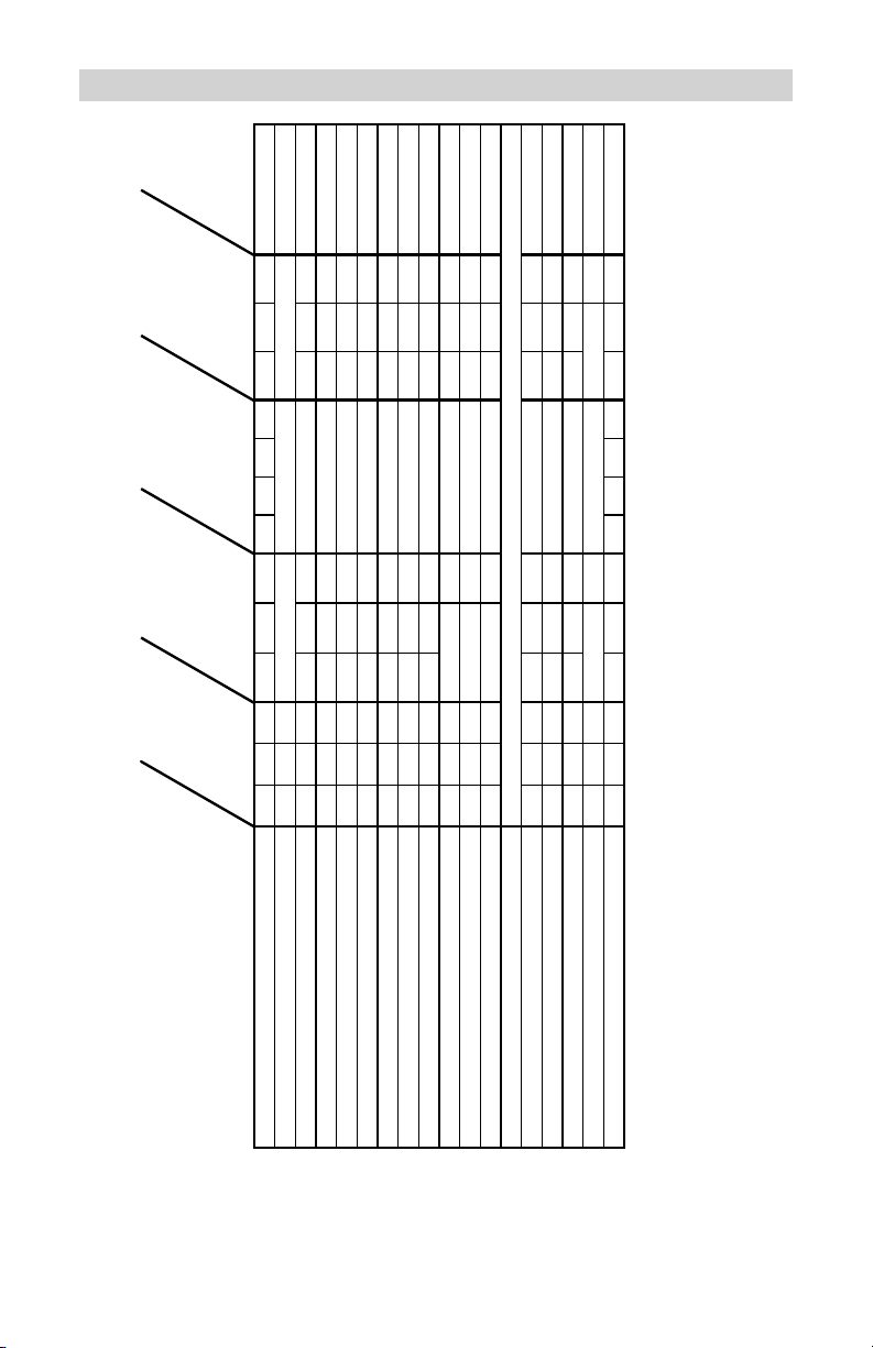
CONTROL PANEL GUIDE14.
SC-10030A CONTROL PANEL GUIDE
MODE OF OPERATION
C
h
a
r
g
e
d
C
h
a
r
g
i
ng
C
o
n
n
e
c
t
e
d
B
a
t
t
e
r
y %
V
o
l
t
a
ge
A
l
t
e
r
n
a
t
or
%
1
2
V
S
t
a
n
d
a
r
d
1
2
V
A
G
M
1
2
V
G
e
l
C
e
l
l
6
V
S
t
a
n
d
a
r
d
S
m
a
l
l
B
a
t
t
e
r
y
M
e
d
i
u
m
t
o
L
a
r
g
e B
a
t
t
e
r
y
E
n
gi
ne
S
t
a
r
t
Digital
Display
Initial power-up, battery not detected O O 0.0
No battery or reversed battery detected 0(%) or 0.0(V)
Battery tester activated O 0~100
Battery tester with charged battery O O O 100
Battery tester with no battery O 0
Voltage meter activated O 0.0~17.0
Alternator tester activated O 0~199
Alternator tester on good alternator O O O 85~130
Alternator tester on bad alternator O O 0~84,131~199
Small Battery (2A) charge O O O xx(%) or xx.x(V)
Medium to Large Battery (12AŻŹ$FKDUJ
H O O O xx(%) or xx.x(V)
Charge complete - Maintain Mode started O O 100(%) or xx.x(V)
Engine Start
Waiting for engine crank O O O O 1.0~16.0
Cranking engine O O O 5ĺ
Cool down after cranking O B 180ĺ
Desulfation mode activated B O 15(%) or 16(V)
Charge aborted O *bad bat (B)
Empty spaces indicate LEDs that are off.
* display blinks "bad" then "bat" repeatedly
O indicates an LED that is on continuously. x indicates a digit 0 ~ 9. ĺLQGLFDWHVDFRXQWGRZQRQWKHGLVSOD\
User selected
User selected
User selected
User selected
User selected
User selected
User selected
User selected
User selected
User selected
User selected
User selected
User selected User selected
User selected User selected
User selected
User selected
User selected
User selected
User selected
User selected
• 10 •
Page 13

USING THE BUILT-IN BATTERY TESTER15.
OVERVIEW: This battery charger has a built-in battery tester that displays
either an accurate battery voltage or an estimate of the battery’s relative
charge based on the battery voltage and the Battery Council International
scale.
TESTING15.1 SEQUENCE
There are four basic steps required to use the SC-10030A as a battery 1.
tester:
Connect the battery clamps (see sections 6 and 7). 2.
Connect the charger power cord to a 120V AC wall outlet. 3.
If necessary, press the Battery Type button until the correct type is 4.
indicated.
Read the voltage on the digital display or press the digital DISPLAY 5.
button to set the tester to Battery % and read the battery percent.
TESTER AND CHARGER15.2
When rst turned on, the SC-10030A operates only as a tester, not as a
charger. To continue to use it as only a tester, avoid pressing the BATTERY
SIZE button. Selecting a charge rate activates the battery charger and deactivates the tester. Pressing the BATTERY SIZE button when the ENGINE
START LED is lit (except during the 180 second cool down) will shut off the
charger and activate the tester.
POWER-UP IDLE TIME LIMIT15.3
If no button is pressed within 15 minutes after the SC-10030A is rst powered up, it will automatically switch from tester to charger, if a battery is
connected. In that case, the charger will be set for the SMALL BATTERY
SIZE and 12V AGM BATTERY TYPE.
TESTER WITHOUT TIME LIMIT15.4
If either the DIGITAL DISPLAY or BATTERY TYPE button is pressed with-
in the rst 15 minutes after the SC-10030A is powered up, it will remain a
tester (not a charger) indenitely, unless a charge rate is selected.
TESTING AFTER CHARGING15.5
After the SC-10030A has been changed from tester to charger (by select-
ing a charge rate), it remains a charger. To change the SC-10030A back
to a tester, press the BATTERY SIZE button until all BATTERY SIZE LEDs
are all off.
TESTER STATUS LEDs15.6
When the SC-10030A is operating as a battery tester, the status LEDs
light under the following conditions:
The CHARGED (green) LED will light if a charged battery is tested. •
• 11 •
Page 14

The CHARGING LED does not light in the battery test mode.•
The • CONNECTED LED lights when a properly connected battery is de-
tected.
When the tester digital display is set to • VOLTAGE, the CHARGED and
CHARGING LEDs won’t light (it could be testing a battery or an alternator).
INITIAL PERCENT CALCULATION15.7
When a battery % is calculated for the rst time after connecting a battery,
the digital display will show three dashes (“---”) for a period as long as
several seconds while the tester analyzes the battery.
NOTES FOR TESTING BATTERY %15.8
A recently charged battery could have a temporarily high voltage due
to what is known as “surface charge.” The voltage of such a battery will
gradually drop during the period immediately after the charging system is
disengaged. Consequently, the tester could display inconsistent values for
such a battery. For a more accurate reading, the surface charge should be
removed by temporarily creating a load on the battery, such as by turning
on lights or other accessories.
The battery % ranges from 0 to 100.
The battery tester is only designed to test batteries. Testing a device with
a rapidly changing voltage could yield unexpected or inaccurate results.
USING THE BUILT-IN ALTERNATOR TESTER16.
This battery charger has a built-in alternator tester that displays either
an accurate alternator voltage or an estimate of the alternator’s relative
output compared to normal alternators. The Alternator % values displayed
should be taken as general reference, not precise diagnosis. The alternator tester functions the same as the battery tester (see previous section of
this manual for details) with a few differences.
TESTING SEQUENCE 16.1
There are three basic steps required to use the SC-10030A as an alternator tester.
1. Connect the battery clamps (see sections 6 and 7).a.
2. Connect the charger power cord to a 120V AC wall outlet. b.
3. Start the vehicle and turn on the vehicle’s headlights. Read the c.
voltage on the digital display or press the DIGITAL DISPLAY button to
set the tester to ALTERNATOR % and read the alternator percent.
TESTER STATUS LEDs16.2
When the SC-10030A is operating as an alternator tester, the status LEDs
light under the following conditions.
• 12 •
Page 15

The • CHARGED (green) LED will light if the output of the charging system
is at the normally desired level.
The CHARGING LED does not light in the alternator test mode.•
The • CONNECTED LED lights if the tester detects a connection.
When the tester digital display is set to • VOLTAGE, the CHARGED and
CHARGING LEDs won’t light (it could be testing a battery or an alternator).
ALTERNATOR TESTING NOTES16.3
The alternator percent display can range from 0 to 199.•
The DIGITAL • DISPLAY cannot be set to ALTERNATOR % during charg-
ing.
An • ALTERNATOR % of 0 does not indicate an ALTERNATOR output of
0V, it indicates an output too low to charge the battery.
An • ALTERNATOR % of 199 does not indicate an Alternator Voltage
nearly twice the voltage of a normal alternator.
BATTERY PERCENT AND CHARGE TIME17.
This charger adjusts the charging time in order to charge the battery completely, efciently and safely. The microprocessor automatically makes the
necessary decisions. However, this section includes guidelines that can be
used to estimate charging times.
The duration of the charging process depends on three factors:
Battery State17.1 – If a battery has only been slightly discharged, it can be
charged in less than a few hours. The same battery could take up to 10
hours if very weak. The battery state can be estimated by using the built-in
tester. The lower the reading, the longer charging will take.
Battery Rating17.2 – A higher rated battery will take longer to charge than
a lower rated battery under the same conditions. A battery is rated in
ampere-hours (AH), reserve capacity (RC) and cold cranking amps (CCA).
The lower the rating, the quicker the battery will be charged.
Charge Rate – 17.3 The charge rate is measured in amps. This charger pro-
vides charge rates of 2A, 12A, and 30A. The 100A rate is for engine start
only. The 2A rate is for charging smaller batteries such as those used for
motorcycles and garden tractors. Such batteries should not be charged
using the MEDIUM TO LARGE BATTERY setting, which is for charging
larger batteries. In the MEDIUM TO LARGE BATTERY mode, the charger
begins at the 12A rate and increases the charge rate if it determines that
the battery can accept the 30A rate. All charging modes will decrease the
charge rate as the battery approaches maximum charge.
After the charging process has started, the digital display can be used to
determine charging progress by selecting the BATTERY % mode.
• 13 •
Page 16

There are some important facts to keep in mind when charging a battery.
When the display indicates 77% charged, the battery has been charged •
enough to start most vehicles and has already been charged as much as
by many other battery chargers.
When the display indicates 85% charged, the battery has already been •
charged at least as much as by most other battery chargers.
The battery % shown in tester mode is an estimate based on the bat-•
tery voltage and the Battery Council International scale. The battery %
shown in charger mode is an estimate of the relative charge in the battery
compared to the charge it should have if the charging process is allowed
to complete.
The battery % shown in tester mode can be used to estimate the relative •
charge time. The lower the % shown, the longer the charge time for a
given battery.
The battery % shown in charger mode is an indication of the relative •
progress of the charging process. The higher the battery % displayed, the
less charge time remains.
The more a battery is discharged, the faster it absorbs charge from a •
charger. That means that the battery % increases faster at the beginning
of the charging process than at the end. In other words, it takes longer for
the battery to absorb the last few percent of charge than the rst several
percent.
CHARGING TIPS18.
Read this entire manual before using your charger. The tips below serve
only as a guide for specic situations.
If your vehicle won’t start18.1 : You don’t need to fully charge the battery to
start your vehicle. If the charger won’t start your vehicle using the ENGINE START rate, try charging the battery using the MEDIUM TO LARGE
BATTERY setting for 10 or 15 minutes. That should charge the battery
enough to allow the ENGINE START rate to start the vehicle. If the vehicle
will then be operated continuously for an extended period (such as a long
drive), the vehicle could charge the battery back to normal during that
period. If the vehicle will only be operated for a short period (short drive),
the battery might need to be charged again before it could start the vehicle
again.
Reviving your battery18.2 : If you only wish to charge your battery enough
to operate your vehicle, you don’t need to wait for the entire charging
process to be completed. When the charger displays a battery % of 77 or
more, the battery has usually been charged enough for the vehicle to start
and operate normally.
• 14 •
Page 17

Completing an interrupted charge18.3 : If the charging process has been
interrupted and restarted after the charger displays a battery % of 85 or
more, the charger could go straight to Maintain Mode. However, if the
original charge was started using the MEDIUM TO LARGE BATTERY rate,
the charge can often be completed using the SMALL BATTERY setting.
MAINTENANCE INSTRUCTIONS19.
The charger is designed and built with high quality materials requiring only
a minimum amount of care.
After use, use a dry cloth to wipe all battery corrosion and other dirt or oil 19.1
from terminals, cords, and the charger case.
Cords should be coiled when the charger is not being used to prevent 19.2
damage.
Other servicing should be performed by qualied service personnel.19.3
The charger will draw a small amount of current from the battery(ies), a 19.4
few milliamps, when not charging or maintaining. If the battery(ies) are
going to be stored for an extended period of time (several months) without
being charged, it is best to disconnect the charger battery clamps to keep
the charger from discharging the battery(ies) over time.
• 15 •
Page 18

TROUBLESHOOTING20.
PROBLEM POSSIBLE CAUSE SOLUTION
The battery is connected
and the charger is on,
but isn’t charging.
Indicator lights are lit in
an erratic manner not
explained in this manual.
The DIGITAL DISPLAY
always ashes before
the battery is completely
charged.
The green CHARGED
LED lights a few minutes
after connecting to the
battery.
Engine crank time is less
than specied.
The charger is in tester
mode, not charger
mode.
You might have accidentally activated a special
diagnostic mode.
The incorrect BATTERY
TYPE may have been
selected.
This will happen if the
battery did not reach full
charge within 24 hours.
May be due to a very
large battery or a bank
of batteries requiring
more power than a
12A30A amp charger
can deliver within 24
hours. The battery may
also be faulty.
The battery may be
fully charged or recently
charged, leaving the battery voltage high enough
to appear to be fully
charged.
The incorrect BATTERY
TYPE may have been
selected.
Starter motor may be
drawing more than 100
amps.
Press the BATTERY
SIZE button to activate
charging and select a
charge rate.
Make sure nothing is
touching the control
panel, then unplug the
charger and plug it in
again.
Reset the charger by
briey unplugging it or
briey disconnecting the
negative battery clamp.
Select the desired rate
(SMALL or MEDIUM TO
LARGE BATTERY) and
BATTERY TYPE again,
if necessary.
If the battery is in a ve-
hicle, turn the headlights
on for a few minutes
to reduce the battery
voltage and try charging
again.
Reset the charger by
briey unplugging it or
briey disconnecting the
negative battery clip.
Select the desired rate
(SMALL or MEDIUM TO
LARGE BATTERY) and
BATTERY TYPE again,
if necessary.
Charge the battery at
the MEDIUM TO LARGE
BATTERY rate for 10 to
15 minutes then repeat
the engine start process.
• 16 •
Page 19

LIMITED WARRANTY21.
SCHUMACHER ELECTRIC CORPORATION,
801 BUSINESS CENTER DRIVE,
MOUNT PROSPECT, ILLINOIS 60056-2179
MAKES THIS LIMITED WARRANTY TO THE ORIGINAL PURCHASER
AT RETAIL OF THIS PRODUCT. THIS LIMITED WARRANTY IS NOT
TRANSFERABLE.
Schumacher Electric Corporation warrants this battery charger for ve
years from date of purchase at retail against defective material or work-
manship. If such should occur, the unit will be repaired or replaced at the
option of the manufacturer. It is the obligation of the purchaser to forward
the unit together with proof of purchase, transportation and/or mailing
charges prepaid to the manufacturer or its authorized representative.
This limited warranty is void if the product is misused, subjected to careless handling, or repaired by anyone other than the manufacturer or its
authorized representative.
The manufacturer makes no warranty other than this limited warranty and
expressly excludes any implied warranty including any warranty for consequential damages.
THIS IS THE ONLY EXPRESS LIMITED WARRANTY AND THE MANUFACTURER NEITHER ASSUMES NOR AUTHORIZES ANYONE TO ASSUME OR MAKE ANY OTHER OBLIGATION TOWARDS THE PRODUCT
OTHER THAN THIS EXPRESS LIMITED WARRANTY. THE MANUFACTURER MAKES NO WARRANTY OF MERCHANTABILITY OR FITNESS
FOR PURPOSE OF THIS PRODUCT AND EXPRESSLY EXCLUDES
SUCH FROM THIS LIMITED WARRANTY.
SOME STATES DO NOT ALLOW THE EXCLUSION OR LIMITATION
OF INCIDENTAL OR CONSEQUENTIAL DAMAGES OR LENGTH OF
IMPLIED WARRANTY SO THE ABOVE LIMITATIONS OR EXCLUSIONS
MAY NOT APPLY TO YOU.
THIS WARRANTY GIVES YOU SPECIFIC LEGAL RIGHTS AND YOU
MAY ALSO HAVE OTHER RIGHTS THAT VARY FROM STATE TO
STATE.
WARRANTY VALIDATION: The enclosed “Warranty Validation Card” must
be completed and mailed within 10 days of product purchase to activate
this limited warranty.
• 17 •
Page 20

• 18 •
Page 21

TM
2
100
12
30
CARGADOR DE BATERIAS
ELECTRÓNICO
CARGA
RÁPIDA a
amperios
CARGA
LENTA a
amperios
ARRANQUE
DE MOTOR a
amperios
MANUAL DEL DUEÑO
Modelo SC-10030A
Para Baterías de 6 y 12 voltios
Cargador de Baterías
Totalmente Automático
Controlado por Microprocesador con
Arranque de Motor más
Probador de Baterías y
Probador de Alternadores
• 19 •
Page 22

• 20 •
Page 23

IMPORTANTE: LEA Y CONSERVE ESTE MANUAL DE INSTRUCCIONES Y
SEGURIDAD.
INSTRUCCIONES DE SEGURIDAD IMPORTANTES1.
CONSERVE ESTAS INSTRUCCIONES – Este manual contiene instruc-1.1
ciones operativas y de seguridad importantes para el cargador de baterías
Modelo SC-10030A.
No exponga el cargador a lluvia ni a nieve.1.2
El uso de un accesorio no recomendado o vendido por el fabricante del 1.3
cargador de baterías podría ocasionar riesgo de incendio, descarga eléctrica o lesión a las personas.
Para reducir el riesgo de peligro del enchufe y cable eléctricos, cuando 1.4
desconecte el cargador, tire del enchufe y no del cable.
No se debería utilizar un alargue a menos que sea absolutamente nec-1.5
esario. El uso indebido del alargue podría ocasionar riesgo de incendio y
descarga eléctrica. Si debe utilizar un alargue, asegúrese de que:
La cantidad, tamaño y la forma de los bornes del enchufe del alargue •
coincidan con los del enchufe del cargador;
El alargue esté adecuadamente conectado y en buena condición eléc-•
trica; y
El tamaño del cable sea lo sucientemente largo para el amperaje de CA •
del cargador, según lo especicado en la Tabla 9.1.
No manipule el cargador si tiene el cable o el enchufe dañados – reemp-1.6
lácelos de inmediato. (Llame al servicio de atención al cliente: 800-621-
5485.)
No manipule el cargador si ha recibido un golpe fuerte, se ha caído o da-1.7
ñado de cualquier modo; llévelo a un técnico calicado. (Llame al servicio
de atención al cliente: 800-621-5485.)
No desarme el cargador, llévelo a un reparador calicado cuando sea 1.8
necesario algún tipo de servicio técnico o reparación. El reensamblado incorrecto podría ocasionar riesgo de descarga eléctrica o incendio. (Llame
al servicio de atención al cliente: 800-621-5485.)
Para reducir el riesgo de descarga eléctrica, desenchufe el cargador del 1.9
tomacorriente antes de intentar realizar alguna actividad de mantenimiento o limpieza. Los controles de apagado no reducirán este riesgo.
ADVERTENCIA – RIESGO DE GASES EXPLOSIVOS.
ES PELIGROSO TRABAJAR CERCA DE UNA BATERÍA DE PLOMO Y
ÁCIDO. LAS BATERÍAS GENERAN GASES EXPLOSIVOS DURANTE
SU FUNCIONAMIENTO NORMAL. POR ESO, ES DE SUMA IMPORTANCIA QUE SIGA LAS INSTRUCCIONES CADA VEZ QUE UTILICE
EL CARGADOR.
• 21 •
Page 24

PARA REDUCIR EL RIESGO DE EXPLOSIÓN DE LA BATERÍA, SIGA
ESTAS INSTRUCCIONES ADEMÁS DE LAS PUBLICADAS POR EL
FABRICANTE DE CUALQUIER EQUIPO QUE QUIERA USAR CERCA
DE LA BATERÍA. REVISE LAS MARCAS DE PRECAUCIÓN DE ESTOS
PRODUCTOS Y DEL MOTOR.
PRECAUCIONES PERSONALES2.
Considere tener a alguien que lo acompañe para asistirlo cuando trabaje 2.1
cerca de una batería de plomo y ácido.
Tenga a mano mucha agua fresca y jabón en caso de que la piel, la ropa 2.2
o los ojos entren en contacto con el ácido de la batería.
Use protección total para ojos y ropa. Evite tocarse los ojos mientras 2.3
trabaja cerca de la batería.
Si el ácido de la batería entra en contacto con la piel o la ropa, lave de 2.4
inmediato con agua y jabón. Si el ácido entra en los ojos, deje que éstos
se llenen de agua fría corriente al menos 10 minutos y consiga atención
médica inmediata.
NUNCA fume ni permita que haya chispas o llamas cerca de la batería o 2.5
del motor.
Sea extremadamente cauteloso para reducir el riesgo de dejar caer una 2.6
herramienta metálica en la batería, ya que podría echar chispas o causar
un cortocircuito en la batería o en otra parte eléctrica que pudiera ocasio-
nar una explosión.
Retire los artículos metálicos personales como anillos, pulseras, collares 2.7
y relojes cuando trabaje con una batería de plomo y ácido, dado que ésta
puede ocasionar una corriente de cortocircuito lo sucientemente alta
como para soldar al metal algún anillo u otro artículo, y provocar así una
quemadura grave.
Use el cargador para cargar una batería de PLOMO Y ÁCIDO, exclusi-2.8
vamente, ya que no está diseñado para suministrar energía a un sistema
eléctrico de bajo voltaje distinto de una aplicación de motor de arranque.
No utilice el cargador de batería para cargar baterías secas, comúnmente
utilizadas en artefactos domésticos. Estas baterías podrían explotar y
ocasionar una lesión en personas y un daño en los bienes.
NUNCA cargue una batería congelada.2.9
PREPARACIÓN DE LA CARGA3.
Si es necesario quitar la batería del vehículo para cargarla, siempre retire 3.1
el terminal a tierra de la batería primero. Asegúrese de que todos los accesorios dentro del vehículo estén apagados para evitar causar un arco.
Asegúrese de que el área que rodea la batería esté bien ventilada durante 3.2
la carga.
Limpie los terminales de la batería. Sea cuidadoso para así evitar que la 3.3
corrosión entre en contacto con los ojos.
• 22 •
Page 25

Agregue agua destilada en cada celda hasta que el ácido de la batería 3.4
alcance el nivel especicado por el fabricante. Evite que se rebase. En el
caso de una batería sin capas de celda desmontables, como las baterías
de plomo y ácido reguladas por una válvula, siga atentamente las instruc-
ciones de recarga del fabricante.
Lea las precauciones especícas del fabricante de baterías mientras 3.5
realiza la carga además de los índices de carga sugeridos.
Determine el voltaje de la batería teniendo en cuenta el manual del 3.6
propietario del automóvil y asegúrese de que el interruptor del selector de
voltaje de salida está puesto en el voltaje correcto. Si el cargador tiene un
índice de carga ajustable, primero cargue la batería en el índice más bajo.
UBICACIÓN DEL CARGADOR4.
Ubique el cargador lo más alejado posible de la batería en la medida que 4.1
los cables de CC se lo permitan.
Nunca deposite el cargador directamente sobre la batería que se está car-4.2
gando; los gases de la batería corroerán y dañarán el cargador.
Nunca permita que el ácido de la batería gotee sobre el cargador cuando 4.3
esté leyendo el peso especíco electrolítico o llenando de la batería.
No maneje el cargador en un área cerrada o con poca ventilación.4.4
No coloque una batería sobre el cargador.4.5
PRECAUCIONES DE LA CONEXIÓN CC5.
Conecte y desconecte los sujetadores de salida de corriente CC sólo 5.1
luego de apagar los interruptores del cargador (posición “off”) y retirar el
cable CA del enchufe eléctrico. Nunca deje que los sujetadores se toquen
entre ellos.
Coloque los sujetadores a la batería y chasis, según lo indicado en 6.5, 5.2
6.6, y 7.2 hasta 7.4.
SIGA ESTOS PASOS AL INSTALAR UNA BATERÍA EN EL VEHÍCU-6.
LO.
UNA CHISPA CERCA DE LA BATERÍA PODRÍA PROVOCAR UNA EXPLOSIÓN. PARA EVITAR ESTO:
Coloque los cables CA y CC para reducir el riesgo de daño provocado por 6.1
el capó, la puerta o una parte móvil del motor.
Manténgase alejado de paletas de ventiladores, cinturones, poleas y 6.2
demás partes que puedan causar una lesión a las personas.
Revise la polaridad de los terminales de la batería. El terminal de la bat-6.3
ería de polaridad POSITIVA (POS, P, +) por lo general tiene un diámetro
mayor que el terminal de polaridad NEGATIVA (NEG, N,–).
• 23 •
Page 26

Determine qué terminal tiene conexión a tierra (conectado) con el chasis. 6.4
Si el terminal negativo está conectado al chasis (como en la mayoría de
los vehículos), véase (6.5). Si el terminal positivo es el que está conectado al chasis, véase (6.6).
Para un vehículo de conexión a tierra negativa, conecte el sujetador 6.5
POSITIVO (ROJO) desde el cargador de la batería hacia el terminal sin
conexión a tierra POSITIVO (POS, P, +). Conecte el sujetador NEGATIVO
(NEGRO) al chasis del vehículo o bloque del motor, lejos de la batería.
No conecte el sujetador al carburador, a las mangueras de combustible
o planchas de metal de la carrocería. Conecte a una parte metálica del
calibre pesado de la estructura o bloque del motor.
Para un vehículo de conexión a tierra positiva, conecte el sujetador 6.6
NEGATIVO (NEGRO) desde el cargador de la batería hacia el terminal sin
conexión a tierra NEGATIVO (NEG, N, –). Conecte el sujetador POSITIVO (ROJO) al chasis de vehículo o bloque del motor, lejos de la batería.
No conecte el sujetador al carburador, a las mangueras de combustible
o planchas de metal de la carrocería. Conecte a una parte metálica del
calibre pesado de la estructura o bloque del motor.
Al desconectar el cargador, desenchufe los interruptores, desconecte el 6.7
cable de corriente alterna, retire los sujetadores del chasis del vehículo y
luego el del terminal de la batería.
Vea las INSTRUCCIONES OPERATIVAS para mayor información sobre 6.8
la carga.
SIGA ESTOS PASOS CUANDO LA BATERÍA ESTÉ AFUERA DEL 7.
VEHÍCULO.
UNA CHISPA CERCA DE LA BATERÍA PODRÍA PROVOCAR SU EXPLOSIÓN. PARA EVITAR ESTO:
Revise la polaridad de los terminales de la batería. El terminal de la bat-7.1
ería de polaridad POSITIVA (POS, P, +) por lo general tiene un diámetro
mayor que el terminal de polaridad NEGATIVA (NEG, N,–).
Añada por lo menos un cable de batería aislado calibre (AWG – calibre 7.2
estadounidense de cable) 6 de 24 pulgadas al terminal de la batería con
polaridad NEGATIVA (NEG, N, -).
Conecte el sujetador del cargador POSITIVO (ROJO) al terminal POSI-7.3
TIVO (POS, P, +).
Ubíquese y libere el extremo del cable lo más lejos posible de la batería – 7.4
luego conecte el sujetador del cargador NEGATIVO (NEGRO) para liberar
el extremo del cable.
No se acerque a la batería cuando realice la conexión nal.7.5
Cuando desconecte el cargador, hágalo siempre en la secuencia inversa 7.6
al procedimiento de conexión y primero interrumpa la conexión mientras
esté tan lejos de la batería como sea posible.
Una batería marítimo (de barco) se debe retirar y cargar en tierra. Su 7.7
• 24 •
Page 27

carga a bordo requiere un equipo especialmente diseñado para el uso
25 50 100 150
(7.6) (15.2) (30.5) (45.6)
0 2 18 18 18 16
2 3 18 18 16 14
3 4 18 18 16 14
4 5 18 18 14 12
5 6 18 16 14 12
6 8 18 16 12 10
8 10 18 14 12 10
10 12 16 14 10 8
12 14 16 12 10 8
14 16 16 12 10 8
16 18 14 12 8 8
18 20 14 12 8 6
a
Si la cantidad de entrada de un cargador es dada en vatios en
vez de amperios, la medida correspondiente de amperios es
determinada si se dividen los vatios por la cantidad de voltaje ±
Por ejemplo:
1250 vatios/125 voltios = 10 amperios
Longitud del cable, pies (m)
Medida del cable segun la AWG
Entrada de corriente
alterna en amperios
a
A no
menos de
De
marítimo.
CONEXIONES AC8.
Este cargador de batería es para usar en un circuito nominal de 120 8.1
voltios.
PELIGRO – Nunca cambie un cable CA o enchufe suministrados – si no
entra en el tomacorriente, solicite la instalación adecuada de un electricista calicado. La conexión inadecuada puede resultar en riesgo de
descarga eléctrica.
MEDIDA DEL CABLE SEGUN LA AWG9.
• 25 •
Page 28

INSTRUCCIONES DE ENSAMBLADO10.
Junto con el cargador de batería, encontrará dos abrazaderas cubiertas 10.1
para almacenar los prensacables.
Para la instalación, alinee las dos presillas para que coincidan con los dos 10.2
receptáculos, y empuje hasta que escuche un ruido seco.
Cubra los prensacables luego de desenchufar el cable de la energía del 10.3
tomacorriente CA de la pared y deposite el cargador en un lugar seco.
USO DEL ARRANQUE DEL MOTOR11.
El cargador de batería se puede utilizar para arrancar el auto si la batería
está baja. Siga estas instrucciones sobre cómo usar la característica de
ARRANQUE DEL MOTOR.
IMPORTANTE: Siga todas las instrucciones y precauciones de seguridad
cuando cargue la batería. Use protección total para ojos y ropa. Cargue la
batería en un área bien ventilada.
IMPORTANTE: Usar la característica de ARRANQUE DEL MOTOR SIN
que el vehículo tenga una batería instalada podría dañar su sistema
eléctrico.
Con el cargador enchufado y conectado a la batería y al chasis, presione 11.1
el botón de TAMAÑO DE LA BATERÍA (BATTERY SIZE) hasta que se
encienda el LED DE ARRANQUE DEL MOTOR (ENGINE START LED). El
modo visor se jará automáticamente en VOLTAJE (VOLTAGE).
Arranque el motor por no más de 5 segundos. Si el motor no enciende, 11.2
espere 3 minutos antes de intentar nuevamente.
Luego de que el motor se enciende, desenchufe el cable de energía antes 11.3
de desconectar los bornes de salida.
Limpie y guarde el cargador en un lugar seco.11.4
NOTA: durante la secuencia de arranque mencionada anteriormente, el
cargador se prepara para uno de los tres estados.
Espera para arranque11.5 – El cargador espera hasta que el motor haya
efectivamente arrancado antes de liberar 100 amps para el arranque del
motor. El cargador entrega la carga a una tasa de hasta 12 amps mien-
tras espera, y se restaurará si el motor no arranca dentro de 15 minutos.
(Si el cargador se restablece, se prepara para un TAMAÑO DE BATERÍA
PEQUEÑA y un TIPO DE BATERÍA AGM 12V). Mientras espera para el
arranque, el visor digital muestra el voltaje de la batería (no puede jarse
el porcentaje)
Arranque 11.6 – cuando se detecte el arranque, el cargador automáticamente
liberará su corriente de salida máxima (al menos 100A) conforme a lo
requerido por el sistema de arranque, durante 5 segundos o hasta que
el arranque del motor se detenga. El visor digital muestra un conteo
regresivo del tiempo en segundos del arranque restante. Empieza en 5 y
cuenta hasta 0.
• 26 •
Page 29

Enfriamiento11.7 – Luego del arranque, el cargador entra en un estado
obligatorio de 3 minutos de enfriamiento (180 segundos). Durante este
período, no se pueden modicar las conguraciones. Los botones se
ignoran. El visor digital indica el tiempo restante de enfriamiento en se-
gundos. Empieza en 180 y cuenta hasta 0. El LED DE ARRANQUE DEL
MOTOR titila una vez por segundo. Durante el período de enfriamiento,
no se libera corriente a la batería. Transcurridos 3 minutos, el LED DE
ARRANQUE DEL MOTOR dejará de titilar y se iluminará continuamente,
indicando que otro ciclo de arranque puede comenzar. El visor digital
dejará de mostrar el conteo regresivo para exhibir el voltaje de la batería.
En ese momento se iluminará el LED DE CARGA.
NOTAS DEL ARRANQUE DEL MOTOR:
Si la batería se desconecta durante el período de enfriamiento, el carga-•
dor se reconectará.
INSTRUCCIONES OPERATIVAS12.
INFORMACIÓN GENERAL: es muy simple utilizar este cargador de
batería. Primero, conecte la batería y corriente CA. Luego, elija el TIPO y
TAMAÑO DE BATERÍA indicados para su batería. El cargador hará todo
automáticamente. En esta sección se dan algunos detalles.
CARGA:12.1 si el cargador no detecta una batería correctamente conectada,
el LED CONECTADO no se iluminará. La carga no comenzará a menos
que el LED CONECTADO esté encendido. Cuando se inicia la carga, el
LED DE CARGA se iluminará.
APAGADO AUTOMÁTICO:12.2 cuando se selecciona el TAMAÑO PEQUEÑO O MEDIANO A GRANDE DE LA BATERÍA, el cargador está listo para
realizar una carga automática. Cuando se lleva a cabo una carga automática, el cargador interrumpirá automáticamente la carga luego de que
la batería esté cargada.
CARGA ABORTADA: 12.3 si no se puede completar normalmente, la carga se
abortará. En este caso, la potencia del cargador se apaga y el visor digital
titila. En este estado, el cargador ignora todos los botones. Para reconectar luego de una carga abortada, desconecte la batería o desenchufe el
cargador.
MODO DESULFATACIÓN:12.4 si una batería no se carga por un tiempo
largo, se puede sulfatar y no tolerar una carga normal. Si el cargador
detecta una batería sulfatada, cambiará a un modo especial de funcionamiento diseñado para esas baterías. La activación del modo especial de
desulfatación se indica al titilar el LED de CARGA. Si es exitoso, la carga
normal se reiniciará luego de que se desulfura la batería. En ese momen-
to, el LED de CARGA dejará de titilar y de iluminarse constantemente.
La desulfatación podría llevar hasta 10 horas, y si fracasa, la carga se
abortará y el visor digital titilará.
FINALIZACIÓN DE LA CARGA: 12.5
BATERÍA ESTÁNDAR 12V O 6V: • el LED CARGADO (verde) indica la
• 27 •
Page 30

nalización de la carga; cuando está iluminado, el cargador ha detenido
DIGITAL DISPLAY
la carga y pasado al Modo de Mantenimiento de operación.
BATERÍA AGM 12V O DE CÉLULA DE GEL:• el LED DE CARGADO
aparece cuando la batería se cargó lo suciente para su uso normal.
Finalizada la carga, el LED DE CARGADO estará encendido y el voltaje
será inferior a 14V.
MODO DE MANTENIMIENTO12.6 : cuando el LED DE CARGADO (verde)
esté encendido, el cargador ha iniciado el Modo de Mantenimiento, conocido también como Control de Modo Flotante. En este modo, el cargador
mantiene la batería totalmente cargada al liberar una pequeña cantidad
de corriente, cuando es necesario. El voltaje se mantiene al nivel determi-
nado por el TIPO DE BATERÍA seleccionado.
NOTA: para baterías AGM 12V y baterías de CÉLULA DE GEL 12V, el
MODO de CARGADO podría iluminarse antes de iniciado el modo de
mantenimiento.
NOTAS GENERALES SOBRE LA CARGA:12.7 el cargador está diseñado
para controlar su ventilador de enfriamiento para un funcionamiento
eciente; sin embargo, el ventilador podría correr constantemente cuando
se mantiene una batería totalmente cargada. El ventilador no corre en el
Modo Vericador.
Si se cambia el modo de carga luego de iniciada (presionando el botón
TAMAÑO DE BATERÍA o TIPO DE BATERÍA), se reiniciará el proceso de
carga.
El voltaje mostrado durante la carga por lo general será mayor que el
voltaje en reposo de la batería.
El voltaje mostrado durante la carga es el voltaje de la batería y no el
voltaje RMS de carga.
CONTROLES DEL CARGADOR13.
DIGITAL DISPLAY BUTTON (BOTÓN DE VISOR DIGITAL) 13.1
Use este botón para jar la función de visor digital, conforme a uno de los
siguientes:
• 28 •
Page 31

BATTERY % (% de BATERÍA):• el visor digital muestra un cálculo del
porcentaje de carga de la batería conectada a las abrazaderas de la
batería del cargador.
VOLTAGE (VOLTAJE): • el visor digital muestra el voltaje en las abrazad-
eras de la batería del cargador en voltios de corriente continua.
ALTERNATOR % (ALTERNADOR %): • el visor digital muestra un por-
centaje estimado de salida del sistema de carga del vehículo conectado
a las abrazaderas de la batería, según lo comparado con un sistema de
funcionamiento adecuado.
BATTERY TYPE BUTTON (BOTÓN DE TIPO DE BATERÍA) 13.2
Use este botón para jar el tipo de batería que se va a cargar, conforme a
uno de los siguientes.
12V STANDARD (ESTÁNDAR 12V):• Este tipo de batería se utiliza
generalmente en autos, camiones y motocicletas. Estas baterías tienen
tapas de ventilación y se identican como de “bajo mantenimiento” o “sin
mantenimiento”.
12V AGM (AGM 12V): • las baterías AGM tienen cajas selladas sin tapas
de ventilación, y vienen en varios tamaños.
12V GEL CELL (BATERÍA DE CÉLULA DE GEL 12V):• las baterías de
célula de gel tienen cajas selladas sin tapas de ventilación y por lo general son más pequeñas que los demás tipos.
6V STANDARD (ESTÁNDAR 6V):• este es el tipo de batería usualmente
utilizado en vehículos antiguos y algunos especializados. El tipo de
batería ESTÁNDAR 6V no puede seleccionarse para baterías mayores a
8,5V CC.
Las baterías deberían identicarse con su tipo. Si está cargando una
batería sin identicación, revise el manual del artículo que la utiliza. Si
se desconoce el tipo de batería, use la AGM 12V. Asegúrese de que la
batería cumple con las instrucciones de seguridad.
• 29 •
Page 32

BATTERY SIZE BUTTON (BOTÓN DE TAMAÑO DE LA BATERÍA) 13.3
Utilice este botón para establecer el índice máximo de carga en uno de
los siguientes:
SMALL BATTERY (BATERÍA PEQUEÑA):• Proporciona un índice de
carga de hasta 2A. Destinado para cargar baterías pequeñas, como
por ejemplo, aquellas que se utilizan en los tractores de jardín, motos
de nieve y motocicletas. La 2A no está destinada para utilizarse en un
cargador de mantenimiento para baterías más grandes.
MEDIUM TO LARGE BATTERY (BATERÍAS MEDIAS A GRANDES):•
Automáticamente cambia entre 12 y 30 amps, o proporciona 12 amps
continuos dependiendo de la batería. Utilizar para cargar baterías de
capacidad media a grande. No está destinada para uso industrial.
ENGINE START (ENCENDIDO DEL MOTOR): • Proporciona 100 amps
para arrancar un motor con una batería débil o baja. Siempre utilícelo
junto con una batería.
APAGADO:• El cargador vuelve al modo de probador y las LED de la
BATERÍA PEQUEÑA, la BATERÍA MEDIANA A GRANDE y el ENCENDIDO DEL MOTOR permanecen APAGADAS.
• 30 •
Page 33

GUIA DE CONTROL DEL TABLERO DE MANDOS14.
GUIA DE CONTROL DEL TABLERO DE MANDOS PARA MODELO SC-10030A
MODO DE OPERACIÓN
C
a
r
g
a
d
o
C
a
r
ga
n
d
o
C
o
n
e
c
t
a
d
o
B
a
t
e
r
í
a
%
Vo
l
t
a
j
e
A
l
t
e
r
n
a
d
o
r
%
N
o
r
m
a
l
1
2
V
A
G
M
1
2
V
D
e
C
é
l
u
l
a
G
e
l
1
2
V
N
o
r
m
a
l
d
e
6
V
B
a
t
e
r
í
a
P
e
q
u
e
ñ
a
D
e
b
a
t
e
r
í
a
M
e
di
a
n
a
a
G
r
a
n
d
e
A
r
r
a
n
c
a
d
o
r d
e
m
o
t
o
r
Muestra
Digital
Encendido inicial, batería no detectada O O 0.0
Batería inversa o no detectada 0(%) ó 0.0(V)
Probador de batería activado O 0~100
Probador de batería con batería cargada O O O 100
Probador de batería sin batería O 0
Medidor de Voltaje activado O 0.0~17.0
Probador del alternador activado O 0~199
Probador del alternador en buen alternador O O O 85~130
Probador del alternador en mal alternador O O 0~84,131~199
Carga a batería pequeña (2A) O O O xx(%) ó xx.x(V)
Carga a batería median
a o grande (12AŻŹ$ O O O xx(%) ó xx.x(V)
Carga completa-Manténgase en forma empezada O O 100(%) ó xx.x(V)
Arranque del motor
Esperando arrancar el motor O O O O 1.0~16.0
Arranque del motor O O O 5ĺ
Enfriar después del arranque O B 180ĺ
Forma de desulfatear activado B O 15(%) ó 16(V)
Carga interrumpida O *bad bat (B)
Los espacios vacíos indican que LED's están apagadas. B indica que una LED parpadea encendido y apagado. ĺLQGLFDFXHQWDDWUiVHQHOWDEUHUR
O indica que una LE
D está encendida continuamente. * Muestra titilando "bad" después "bat" repetidamente x indica un dígito del 0-9.
Selección del usuario
Selección del usuario
Selección del usuario
Selección del usuario
Selección del usuario
Selección del usuario
Selección del usuario
Selección del usuario
Selección del usuario
Selección del usuario
Selección del usuario
Selección del usuario
Selección del usuario Selección del usuario
Selección del usuario Selección del usuari
o
Selección del usuario
Selección del usuario
Selección del usuario
Selección del usuario
Selección del usuario
Selección del usuario
• 31 •
Page 34

UTILIZACIÓN DEL PROBADOR DE BATERÍAS INCORPORADO15.
VISIÓN GENERAL: Este cargador de batería posee un probador de
batería incorporado que muestra el voltaje preciso de la batería o un valor
estimado de la carga relativa de la batería basándose en el voltaje de la
batería y la escala del Consejo Internacional de Baterías.
SECUENCIA DE PRUEBA15.1
Existen cuatro pasos básicos necesarios para utilizar SC-10030A como
probador de baterías:
1. Conecte las pinzas para baterías (consulte las secciones 6 y 7). a.
2. Conecte el cable de alimentación del cargador a una salida en la b.
pared de 120V CA.
3. Si es necesario, presione el botón de TIPO DE BATERÍA hasta c.
que se indique el tipo correcto.
4. Lea el voltaje en la pantalla digital o presione el botón de d.
PANTALLA DIGITAL para establecer el probador con respecto al % DE
LA BATERÍA y leer el porcentaje de la batería.
PROBADOR Y CARGADOR15.2
Cuando lo encienda por primera vez, SC-10030A funciona como probador, no como cargador. Para seguir utilizándolo solo como probador, no
presione el botón de TAMAÑO DE LA BATERÍA. Al seleccionar un índice
de carga se activa el cargador de batería y se desactiva el probador. Si se
presiona el botón de TAMAÑO DE BATERÍA cuando el LED del ENCENDIDO DEL MOTOR está iluminado (excepto durante el enfriamiento de
180 segundos) el cargador se apagará y se activará el probador.
LÍMITE DE TIEMPO DE INACTIVIDAD DURANTE EL ENCENDIDO15.3
Si no se presiona algún botón dentro de los 15 minutos luego de que se
enciende por primera vez el SC-10030A, automáticamente, cambiará de
probador a cargador si se conecta una batería. En ese caso, el cargador
estará congurado para una BATERÍA DE TAMAÑO PEQUEÑO y un
TIPO DE BATERÍA DE 12V AGM.
PROBADOR SIN LÍMITE DE TIEMPO15.4
Si se presiona la PANTALLA DIGITAL o el botón de TIPO DE BATERÍA
dentro de los primeros 15 minutos luego de que se enciende el SC-
10030A, permanecerá como probador (no como cargador) indenidamente, salvo que se seleccione un índice de carga.
PROBAR LUEGO DE CARGAR15.5
Luego de cambiar al SC-10030A de probador a cargador (al seleccio-
nar un índice de carga), permanece como cargador. Para cambiar el
SC-10030A nuevamente a probador, presione el botón de TAMAÑO DE
BATERÍA hasta que todos los LED de los TIPOS DE BATERÍA estén
apagados.
• 32 •
Page 35

LOS LED DE ESTADO DEL PROBADOR15.6
Cuando SC-10030A opera como probador de batería, los LED de estado
se iluminan bajo las siguientes condiciones:
El LED correspondiente a CARGADA (verde) se encenderá si se está •
probando la batería cargada.
El LED correspondiente a CARGANDO no se enciende en el modo de •
prueba de batería.
El LED correspondiente a CONECTADO se enciende cuando se detecta •
una batería conectada apropiadamente.
Cuando la pantalla digital del probador se congura para V• OLTAJE, no
se encenderán los LED correspondientes a CARGADA y CARGANDO
(se podría estar probando una batería o un alternador).
CÁLCULO DEL PORCENTAJE INICIAL15.7
Cuando se calcula el % de una batería por primera vez luego de conectar
una batería, la pantalla digital mostrará tres rayas (“---“) durante varios
segundos mientras el probador analiza la batería.
NOTAS PARA PROBAR EL % DE LA BATERÍA15.8
Una batería recientemente cargada podría poseer un voltaje temporalmente alto debido a lo que se conoce como “carga supercial”. El voltaje
de esa batería disminuirá gradualmente inmediatamente después de que
el sistema es desconectado. Por consiguiente, el probador podría mostrar
valores inconsistentes para esa batería. Para una lectura más precisa, se
debe quitar la carga supercial creando, temporalmente, una carga en la
batería, por ejemplo, encendiendo luces u otros accesorios.
El % de la batería varía de 0 a 100.
El probador de batería solo está diseñado para probar baterías. La prueba
de un dispositivo con un voltaje que cambie rápidamente podría arrojar
resultados inesperados o imprecisos.
UTILIZACIÓN DEL PROBADOR DE ALTERNADORES INCORPO-16.
RADO
Este cargador de batería posee un probador de alternadores incorporado
que muestra el voltaje preciso del alternador o un valor estimado de la
salida relativa del alternador comparada con alternadores normales. Los
valores en % del alternador mostrado deben considerarse como referencias generales, no como diagnósticos precisos. El probador de alternadores funciona igual que el probador de baterías (consulte la sección
anterior de este manual para más detalles) con algunas diferencias.
SECUENCIA DE PRUEBA 16.1
Existen tres pasos básicos necesarios para utilizar SC-10030A como
probador de alternadores.
1. Conecte las pinzas para baterías (consulte las secciones 6 y 7). a.
• 33 •
Page 36

2. Conecte el cable de alimentación del cargador a una salida en la b.
pared de 120V CA.
3. Ponga en marcha el vehículo y encienda las luces delanteras. c.
Lea el voltaje en la pantalla digital o presione el botón PANTALLA
DIGITAL para congurar el probador en % DEL ALTERNADOR y lea el
porcentaje del alternador.
LOS LED DE ESTADO DEL PROBADOR16.2
Cuando SC-10030A opera como probador de batería, los LED de estado
se iluminan bajo las siguientes condiciones.
El LED correspondiente a CARGADA (verde) se encenderá si la salida •
del sistema de carga se encuentra en el nivel normalmente deseado.
El LED correspondiente a CARGANDO no se enciende en el modo de •
prueba de alternador.
El LED correspondiente a CONECTADO se enciende si el probador de-•
tecta una conexión.
Cuando la pantalla digital del probador se congura para V• OLTAJE, no
se encenderán los LED correspondientes a CARGADA y CARGANDO
(se podría estar probando una batería o un alternador).
NOTAS SOBRE LA PRUEBA DEL ALTERNADOR16.3
El porcentaje del alternador puede variar de 0 a 199.•
La PANTALLA DIGITAL no se puede congurar para % del ALTERNA-•
DOR durante la carga.
El porcentaje 0 de un ALTERNADOR no indica que la salida del ALTER-•
NADOR sea 0V, indica que la salida es demasiado baja para cargar la
batería.
El porcentaje 199 de un • ALTERNADOR no indica que el Voltaje del Alter-
nador sea aproximadamente el doble de un alternador normal.
PORCENTAJE DE LA BATERÍA Y TIEMPO DE CARGA17.
Este cargador ajusta el tiempo de carga para cargar por completo la
batería de manera ecaz y segura. El microprocesador toma las decisiones necesarias automáticamente. Sin embargo, esta sección incluye
lineamientos que se pueden utilizar para estimar los tiempos de carga.
La duración del proceso de carga depende de tres factores:
Estado de la batería: 17.1 Si la batería se ha descargado levemente, se
puede cargar en menos de un par de horas. La misma batería podría
llevar hasta 10 horas si está muy débil. El estado de la batería se puede
calcular utilizando el probador incorporado. Cuando más baja sea la lectura, la carga llevará más tiempo.
Clasicacióndelasbaterías:17.2 Una batería con clasicación alta requer-
irá más tiempo de carga que una batería con clasicación más baja bajo
• 34 •
Page 37

las mismas condiciones. Las baterías se clasican en amperios-horas
(AH), capacidad de reserva (RC, por sus siglas en inglés) y amperios de
arranque en frío (CCA, por sus siglas en inglés). Cuanto menor sea la
clasicación, la batería se cargará más rápido.
Índice de carga: 17.3 El índice se carga se mide en amperios. Este cargador
proporciona índices de carga de 2A, 12A y 30A. El índice 10A sólo es
para el encendido del motor. El índice 2A es para cargar baterías más
pequeñas, como por ejemplo aquellas utilizadas para las motocicletas
y los tractores de jardín. Estas baterías no se deben cargar utilizando
la conguración BATERÍAS MEDIANAS A GRANDES, que se utiliza
para cargar baterías más grandes. En el modo BATERÍAS MEDIANAS
A GRANDES, el cargador comienza con un índice de 12A y aumenta el
índice de carga si determina que la batería puede aceptar un índice de
30A. Todos los modos de carga disminuirán el índice de carga a medida
que la batería se aproxime a la carga máxima.
Luego de que ha comenzado el proceso de carga, la pantalla digital se
puede utilizar para determinarlo seleccionando el modo de % DE BAT-
ERÍA.
Existen algunos datos importantes para tener en cuenta cuando cargue
una batería.
Cuando la pantalla indica que el 77% está cargado, la batería posee la •
carga suciente como para encender la mayoría de los vehículos y ya ha
sido cargada tanto como lo hacen otros cargadores de baterías.
Cuando la pantalla muestra que el 85% está cargado, la batería ha •
sido cargada, por lo menos, tanto como lo hacen otros cargadores de
baterías.
El % de batería mostrado en el modo probador es un valor estimado •
basado en el voltaje de la batería y la escala del Consejo Internacional
de Baterías. El % de batería mostrado en modo cargador es un valor
estimado de la carga relativa en la batería comparado con la carga que
debería tener si se permite que se complete el proceso de carga.
El % de batería mostrado en el modo probador se puede utilizar para •
calcular el tiempo relativo de carga. Cuanto más bajo sea el % mostrado,
mayor será el tiempo de carga para una batería determinada.
El % de batería mostrado en el modo cargador es una indicación del •
progreso relativo del proceso de carga. Cuanto mayor sea el % de la
batería, menor será el tiempo se carga restante.
Cuanto más descargada esté una batería, más rápido absorberá la carga •
del cargador. Esto signica que el % de la batería aumenta más rápido
al comienzo del proceso de carga que al nal. En otras palabras, le lleva
más tiempo a la batería absorber los últimos porcentajes de carga que
los primeros.
• 35 •
Page 38

DATOS ÚTILES SOBRE LA CARGA18.
Lea todo el manual antes de utilizar el cargador. Los datos útiles que
aparecen a continuación le sirven como guía para situaciones especícas.
Si el vehículo no arranca18.1 : no necesita cargar completamente la batería
para encender el vehículo. Si el cargador no enciende el vehículo utili-
zando el índice de ENCENDIDO DEL MOTOR, intente cargar la batería
con la conguración BATERÍAS MEDIANAS A GRANDES durante 10 o 15
minutos. Esto debería cargar la batería lo suciente como para que con el
índice de ENCENDIDO DEL MOTOR el vehículo arranque. Si el vehículo
funcionará continuamente durante un período largo de tiempo (como por
ejemplo un tramo largo), el vehículo podría cargar nuevamente la batería
en estado normal durante ese período. Si el vehículo solo funcionará por
un período corto (un tramo corto), se debería cargar la batería nuevamente antes de encender el vehículo otra vez.
Reactivar su batería:18.2 Si sólo desea cargar la batería lo suciente como
para utilizar su vehículo, no necesita esperar que se complete todo el
proceso de carga. Cuando el cargador muestra el % de la batería en 77 o
más, por lo general la batería está lo sucientemente cargada para que el
vehículo se pueda encender y utilizar normalmente.
Completar una carga interrumpida18.3 : Si el proceso de carga se ha interrumpido y se ha vuelto a comenzar luego de que el cargador muestre un
% cargado de 85 o más, el cargador puede pasar directamente a Modo
de Mantenimiento. Sin embargo, si la carga original se realizó utilizando
el índice de BATERÍA MEDIANA A GRANDE, por lo general se puede
completar la carga utilizando la conguración BATERÍA PEQUEÑA.
INSTRUCCIONES DE MANTENIMIENTO19.
El cargador está diseñado y construido con materiales de alta calidad que
demandan muy poco cuidado.
Luego del uso, utilice un paño seco para limpiar la corrosión de la batería 19.1
y la suciedad o aceite de los terminales, cables y la caja del cargador.
Los cables se deben enrollar cuando el cargador no se esté utilizando 19.2
para evitar dañarlos.
El personal de mantenimiento calicado debe llevar a cabo otros tipos de 19.3
mantenimiento.
El cargador extraerá una pequeña cantidad de corriente de la/s batería/s, 19.4
pocos miliamperios, cuando no esté cargando o manteniendo. Si la/s
batería/s se van a guardar durante un período largo (varios meses) sin
cargar, es mejor desconectar las pinzas para las baterías del cargador
con el n de evitar que el cargador descargue la/s batería/s con el tiempo.
• 36 •
Page 39

LOCALIZACIÓN Y RESOLUCIÓN DE PROBLEMAS20.
PROBLEMA CAUSA POSIBLE SOLUCION
La batería está conectada
y el cargador encendido,
pero no recibe carga
Las luces indicadoras
están prendidas en una
forma errática no explicado en este manual
El TABLERO DIGITAL
siempre centellea antes
de que la batería esté
completamente cargada.
La luz verde de CARAGADA, se enciende minutos
después de conectar la
batería.
El cargador está en el
modo probador, no el de
carga
Quizás ha activado algún
diagnóstico especial de
mando accidentalmente.
Tal vez el TIPO DE BATERIA haya sido seleccionado accidentalmente.
Esto sucederá si la batería
no ha alcanzado carga
completa en 24 horas.
Esto quizás se deba a
que es una batería muy
grande o que requiera de
más de 12A <>30A Amp
De lo que el cargador
puede abastecer en 24
horas. La batería puede
estar defectuosa.
La batería puede estar
completamente cargada o
pudo haber sido cargada
recientemente, de esta
forma mostrará el voltaje
alto para dar indicio de
que está cargada.
El TIPO DE BATERIA
seleccionado puede ser
incorrecto.
Presione el botón indicador MEDIDA DE LA BATERIA para activar la carga
y seleccione la cantidad
de carga
Asegúrese que nada esté
tocando el tablero de man-
dos, entonces desconecte
el cargador y vuélvalo a
conectar.
Reajuste, desenchufando
el cargador despacio o
desconecte la pinza de
signo positivo. Seleccione la cantidad de
carga deseada. (BATERIA
PEQUEÑA O MEDIANA/
GRANDE) y TIPO DE
BATERIA otra vez, si es
necesario.
Si la batería está montada
en el auto, encienda las
luces de enfrente por unos
minutos para reducir el
voltaje de la batería, e
intente cargar de nuevo.
Reajuste, desenchufando
el cargador despacio o
desconecte la pinza de
signo positivo. Seleccione la cantidad de
carga deseada. (BATERIA
PEQUEÑA O MEDIANA/
GRANDE) y TIPO DE
BATERIA otra vez, si es
necesario.
El período de arranque
del motor es menor
que el especicado
Es probable que al arrancar
el motor esté absorbiendo
más de 100 amperios
• 37 •
Torne el botón de Batería
MEDIANA A GRANDE
dejándolo de 10 a 15
minutos y después repita
el proceso de arranque
del motor.
Page 40

GARANTÍA LIMITADA21.
SCHUMACHER ELECTRIC CORPORATION,
801 BUSINESS CENTER DRIVE,
MOUNT PROSPECT, ILLINOIS 60056-2179
OTORGA ESTA GARANTÍA LIMITADA AL COMPRADOR ORIGINAL AL
MOMENTO DE LA VENTA DE ESTE PRODUCTO. ESTA GARANTÍA
LIMITADA NO ES TRANSFERIBLE.
Schumacher Electric Corporation garantiza este cargador de baterías
durante cinco años desde la fecha de su venta minorista en cuanto a
materiales y mano de obra defectuosos. Si esto ocurriera, se reparará o
reemplazará la unidad según lo decida el fabricante. Es obligación del
comprador enviar al fabricante o al representante autorizado la unidad
con el comprobante de compra, y los gastos de transporte o envío pagos
con antelación.
Esta garantía limitada es nula en el caso de que exista un mal uso del
producto, debido a un manejo descuidado o porque haya sido reparado
por alguien que no haya sido el fabricante o el representante autorizado.
El fabricante no realiza otra garantía además de esta garantía limitada y
excluye expresamente cualquier otro tipo de garantía implícita incluyendo
cualquier garantía con daños consecuentes
ESTA ES LA ÚNICA GARANTÍA LIMITADA EXPRESA Y EL FABRICANTE
NO ASUME NI AUTORIZA QUE OTRA PERSONA ASUMA O REALICE
OTRO TIPO DE OBLIGACIÓN HACIA EL PRODUCTO QUE NO SEA
ESTA GARANTÍA LIMITADA EXPRESA. EL FABRICANTE NO GARAN-
TIZA LA COMERCIABILIDAD O CONVENIENCIA DEL PRODUCTO Y
EXCLUYE EXPRESAMENTE ESTO DE LA GARANTÍA LIMITADA.
ALGUNOS ESTADOS NO PERMITEN LA EXCLUSIÓN O LIMITACIÓN
DE DAÑOS INCIDENTALES O CONSECUENTES O LA DURACIÓN DE
LA GARANTÍA IMPLÍCITA, ES POR ESO QUE LAS LIMITACIONES O
EXCLUSIONES MENCIONADAS ANTERIORMENTE PUEDEN NO APLICARSE A USTED.
ESTA GARANTÍA LE CONCEDE DERECHOS LEGALES ESPECÍFICOS,
USTED PUEDE POSEER OTROS DERECHOS QUE VARÍAN DEPENDI-
ENDO DEL ESTADO.
VALIDACIÓN DE LA GARANTÍA: Se debe completar la “Tarjeta de Validación de la Garantía” adjunta y se la debe enviar dentro
• 38 •
 Loading...