

Page 1
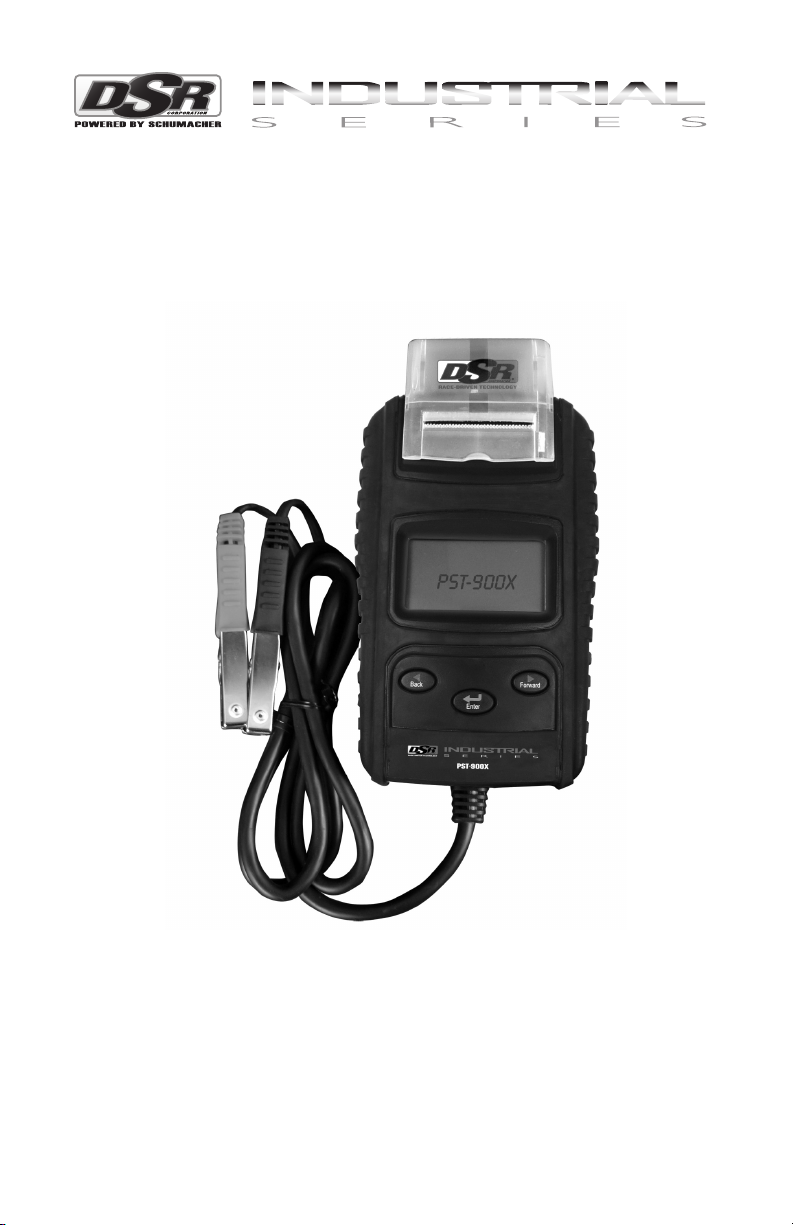
Model PST-900X
™
BATTERY TESTER WITH PRINTER
OWNER’S MANUAL
READ ENTIRE MANUAL BEFORE
USING THIS PRODUCT
00-99-000948/0110
Page 2

Page 3

TABLE OF CONTENTS
SECTION PAGE
FEATURES 1
PERSONAL SAFETY PRECAUTIONS 1
PREPARING TO TEST 2
OPERATING INSTRUCTIONS 2
SETTINGS AND INFORMATION RETRIEVAL 6
GLOSSARY 10
REPLACEMENT PARTS 11
LIMITED WARRANTY 11
Page 4
FE ATUR ES1.
IMPORTANT:1.1
For testing 6 and 12 volt batteries and 12 and 24 volt charging systems.1.
Suggested operation range 32°F (0°C) to 122°F (50°C). 2.
2
1
8
7
3
5
4
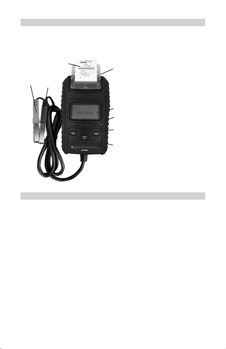
Clear Cover1.
Printer Paper2.
LCD Display3.
FORWARD Button4.
BACK Button5.
ENTER: function selection6.
Negative clamp (BLACK, -)7.
Positive clamp (RED, +)8.
6
PERSONAL SAFETY PRECAUTIONS2.
Consider having someone close enough by to come to your aid when you work 2.1
near a lead-acid battery.
Have plenty of fresh water and soap nearby in case battery acid contacts your 2.2
skin, clothing or eyes.
Wear complete eye and body protection, including safety goggles and 2.3
protective clothing. Avoid touching your eyes while working near the battery.
If battery acid contacts your skin or clothing, immediately wash the area with 2.4
soap and water. If acid enters your eye, immediately ood the eye with cold
running water for at least 10 minutes and get medical attention right away.
NEVER smoke or allow a spark or ame in the vicinity of a battery or engine.2.5
Be extra cautious to reduce the risk of dropping a metal tool onto the battery. 2.6
It might spark or short-circuit the battery or other electrical part that may cause
an explosion.
Remove personal metal items such as rings, bracelets, necklaces and watches 2.7
when working with a lead-acid battery. A lead-acid battery can produce a shortcircuit current high enough to weld a ring or the like to metal, causing a severe
burn.
WARNING2.8 : Pursuant to California Proposition 65, this product contains
chemicals known to the State of California to cause cancer and birth defects or
other reproductive harm.
• 1 •
Page 5

WARNING:2.9 Working in the vicinity of a lead acid battery is dangerous.
Batteries generate explosive gases during normal battery operation. For this
reason, it is of utmost importance, if you have any doubt, that each time before
using your tester, you read these instructions very carefully.
To reduce risk of battery explosion, follow these instructions and those 2.10
published by the battery manufacturer and manufacturer of any equipment
you intend to use in the vicinity of the battery. Observe cautionary markings on
these items.
Do not expose the tester to rain or snow.2.11
PREPARING TO TEST3.
Be sure the area around the battery is well ventilated while the battery is 1.
being tested.
Clean the battery terminals. Be careful to keep corrosion from coming in 2.
contact with your eyes.
Inspect the battery for a cracked or broken case or cover. If the battery is 3.
damaged, do not use the tester.
If the battery is not a sealed maintenance free battery, check the level 4.
of each cell and if necessary, add distilled water until the battery acid
reaches the level specied by the manufacturer. This helps purge
excessive gas from the cells. Do not overll.
If it is necessary to remove the battery from the vehicle to test it, 5.
always remove the ground terminal from the battery rst. Make sure all
accessories in the vehicle are off to ensure you do not cause any arcing.
OPERATING INSTRUCTIONS4.
PAPER LOADING
Hook the tester up to a vehicle battery.1.
Open the clear cover on the top of the tester.2.
Place the roll of paper in the cover with the paper lead on the bottom.3.
Insert the paper into the paper slot until it automatically starts feeding.4.
Make sure the paper comes through the slot in the clear cover before 5.
closing it.
NOTE: This is a thermal printer. If the printer does not print, remove the paper
roll, turn it over and re-insert it.
NOTE: If you have a paper jam, pull the paper out slowly and carefully from
the roll side of the tester and re-insert it properly.
CONNECTING THE TESTER
Before you test a battery in a vehicle, turn off the ignition, all accessories 1.
and loads. Close all of the vehicle’s doors and trunk lid.
Make sure you have put the six 1.5V AA batteries into the battery 2.
compartment. If the 1.5V AA batteries run out of power, the screen will
show POWER LOW. Replace the six 1.5V AA batteries before starting the
test.
NOTE: Nothing will be seen on the display screen until the tester is connected
to a battery.
Make sure the battery terminals are clean. Use a wire brush to clean them 3.
if necessary. NOTE: This tester works best if the battery connectors have
been removed and the battery posts have been cleaned. Any corrosion
between the tester clamps and the battery connectors, or between
the battery connectors and the battery posts, will degrade the tester’s
efciency.
• 2 •
Page 6

Clamp the positive (red) clamp to the positive (POS, P, +) battery post. 4.
Clamp the negative (black) clamp to the negative (NEG, N, -) battery post.
TO TEST THE BATTERY
Once you connect the tester to a battery, the screen will come on and 1.
display BATTERY TEST and the voltage of the battery the tester is
connected to. Press the ENTER button.
The screen will show BATTERY TYPE and STANDARD SLI type of 2.
battery. To change the battery type to VRLA/GEL/AGM/SLA, press the
FORWARD or BACK button. Once the correct battery type has been
selected, press ENTER. (See GLOSSARY for battery denition.)
The screen will show SELECT RATING and either CCA (SAE), IEC, 3.
DIN, JIS or EN battery rating. To change the battery rating, press the
FORWARD or BACK button. Once the correct battery rating has been
selected, press ENTER.
The screen will show SET CAPACITY and a number with the rating you 4.
previously chose. To change the capacity to a different number, press the
FORWARD or BACK button. Once the correct battery capacity has been
selected, press ENTER. The following chart shows the capacity ranges
available for each battery rating.
CCA (SAE): 40 – 2000•
EN: 40 – 2100•
IEC: 30 – 1500•
DIN: 25 – 1300•
JIS: By Battery Type Number•
The screen will show TESTING. After several seconds, the screen will 5.
change to show the results of the test. After the results are displayed,
press ENTER.
NOTE: If the tester determines that the battery voltage is low (based on the
type, rating and capacity that was previously input), it will ask IS BATTERY
CHARGED? This means, has the battery been charged without any drain
placed on it within the last 24 hours. Press the FORWARD or BACK button
to switch between YES and NO. Once the correct option has been selected,
press ENTER.
When the test is complete, the display shows the volts and CCA or 6.
percent of charge. Press the FORWARD or BACK button to select: SOH
(STATE OF HEALTH) or SOC (STATE OF CHARGE). One of ve results
will be displayed:
GOOD AND PASS: The battery is good and capable of holding a charge.•
RECHARGE AND RETEST: The battery is discharged, and the battery •
condition cannot be determined until it is fully charged. Recharge and
retest the battery.
BAD AND REPLACE: The battery will not hold a charge and should be •
replaced.
BAD CELL AND REPLACE: The battery has at least one cell short circuit •
and should be replaced.
LOAD ERROR: The tested battery is bigger than 2000 CCA or 200 Ah, •
or the clamps are not connected properly. Diagnose and correct the
problem, then fully charge the battery and retest it. If the reading is the
same, replace the battery. NOTE: Are there any accessories still turned
on? If yes, turn them off, charge the battery and retest it. If no, replace
the battery since the charging system is working and a good battery
should have accepted a charge.
• 3 •
Page 7

The screen will show CODE and a computer generated code number. 7.
After the code is displayed, press ENTER.
The screen will show PRINT RESULTS and a NO or YES option. To 8.
change the print results choice, press the FORWARD or BACK button.
Once the correct option has been selected, press ENTER and the
tester will print the results of the test or it will go back to the rst screen,
depending on which option was chosen. NOTE: if you select YES to print;
after you’ve printed the number of copies you need, you must select NO
to return to the BATTERY TEST screen.
Remove the clamps from the battery posts after the completion to end the 9.
test.
TO TEST THE CHARGING SYSTEM
Connect the tester as specied in CONNECTING THE TESTER.1.
Once you connect the tester to a battery, the screen will come on and 2.
display BATTERY TEST and the voltage of the battery the tester is
connected to. Press the FORWARD button to get to the SYSTEM TEST,
and then press ENTER.
Turn off all accessories and loads, such as lights, air conditioning, radio, 3.
etc., and close all of the vehicle’s doors and trunk lid before starting the
engine.
When the engine is started, one of the three following results will be 4.
displayed along with the actual reading measured.
CRANKING VOLTS NORMAL: The system is showing normal draw. •
Press ENTER to perform the charging system test.
CRANKING VOLTS LOW: The cranking voltage is below normal •
limits; troubleshoot the starter with the manufacturer’s recommended
procedure.
CRANKING VOLTS NOT DETECTED: The cranking voltage is not •
detected.
If cranking voltage is normal, press ENTER to begin the charging system 5.
test.
The display will show PRESS ENTER FOR CHARGING TEST. Press 6.
ENTER to continue.
The display will show MAKE SURE ALL LOADS ARE OFF. Conrm that 7.
all accessories are off and the doors and trunk are closed. Press ENTER
to continue.
One of the three following results will be displayed along with the actual 8.
reading measured.
LOW CHARGING VOLTS WHEN AT IDLE: The alternator is not •
providing sufcient current to the battery. Check the belts to ensure the
alternator is rotating with the engine running. If the belts are slipping or
broken, replace the belts and retest. Check the connections from the
alternator to the battery. If the connection is loose or heavily corroded,
clean or replace the cable and retest. If the belts and connections are in
good condition, the alternator may need to be replaced, have it checked.
CHARGING SYSTEM NORMAL WHEN AT IDLE: The system is showing •
normal output from the alternator. No problem is detected.
• 4 •
Page 8

HIGH CHARGING VOLTS WHEN AT IDLE: The voltage output from •
the alternator to the battery exceeds the normal limits of a functioning
regulator. Check to ensure there is no loose connection and the ground
connection is good. If there are no connection problems, the regulator
may need to be replaced, have it checked. Since most alternators have
the regulator built-in, this may require you to replace the alternator, have
it checked. The normal high limit of a typical automotive regulator is
14.6+0.05 volts. Check the manufacturer’s specications for the correct
limit, as it will vary by vehicle type and manufacturer.
After you are through with testing the charging system at idle, press 9.
ENTER to test the charging system with accessory loads. The display
screen will show TURN ON LOADS AND PRESS ENTER. Turn on the
blower to high (heat), high beam headlights and rear defogger. Do not
use cyclical loads, such as air conditioning or windshield wipers. Press
ENTER to continue.
NOTE: When testing older model diesel engines, the users need to run the
engine at 2500 rpm for 15 seconds. The display screen will show RUN THE
ENGINE UP TO 2500 RPM 15 SEC.
The tester will test the amount of ripple from the charging system to the 10.
battery. One of the three following results will be displayed along with the
actual reading measured.
RIPPLE DETECTED NORMAL: The diodes are functioning properly in •
the alternator/stator.
NO RIPPLE DETECT: The diodes are functioning properly in the •
alternator/stator.
RIPPLE DETECTED HIGH: One or more of the diodes in the alternator •
are not functioning properly or there is stator damage. Check to ensure
the alternator mounting is sturdy and that the belts are in good shape
and functioning properly. If the mounting and belts are good, the
alternator may need to be replaced, have it checked.
Press ENTER to continue testing the charging system with accessory 11.
loads. One of the three following results will be displayed along with the
actual reading measured.
ALT. LOAD VOLTS HIGH: The output voltage from the alternator to the •
battery exceeds the normal limits of a functioning regulator. Check to
ensure there are no loose connections and that the ground connection
is good. If there are no connection problems, the regulator may need to
be replaced, have it checked. Since most alternators have the regulator
built-in, this may require you to replace the alternator, have it checked.
ALT. LOAD VOLTS LOW: The alternator is not providing sufcient current •
for the system’s electrical loads and the charging current for the battery.
Check the belts to ensure that the alternator is rotating with the engine
running. If the belts are slipping or broken, replace the belts and retest.
Check the connection from the alternator to the battery. If the connection
is loose or heavily corroded, clean or replace the cable and retest. If the
belts and connections are in good working condition, the alternator may
need to be replaced, have it checked.
ALT. LOAD VOLTS NORMAL: The system is showing normal output from •
the alternator. No problem detected.
Press ENTER and the display will show TEST OVER, TURN OFF LOADS 12.
AND ENGINE. Press ENTER to continue.
Turn off all accessory loads and the engine. Press ENTER to continue.13.
• 5 •
Page 9

The screen will show PRINT RESULTS and a NO or YES option. To 14.
change the print results choice, press the FORWARD or BACK button.
Once the correct option has been selected, press ENTER and the
tester will print the results of the test or it will go back to the rst screen,
depending on which option was chosen. NOTE: If you select the YES to
print; after you’ve printed the number of copies you need, you select NO
to return to the rst screen.
Remove the clamps from the battery posts after the completion to end the 15.
test.
SETTINGS AND INFORMATION RETRIEVAL5.
LANGUAGE SELECT
Hook the tester up to a vehicle battery.1.
The tester defaults to the BATTERY TEST display. Press the FORWARD 2.
button twice to get to the LANGUAGE SELECT display.
Press ENTER and the display will show the language options. Press the 3.
FORWARD or BACK buttons to select the language you want the tester to
display.
Press ENTER and the display returns to BATTERY TEST.4.
TEST COUNTER (Displays total number of times tests are performed)
Hook the tester up to a vehicle battery.1.
The tester defaults to the BATTERY TEST display. Press the FORWARD 2.
button three times to get to the TEST COUNTER display.
Press ENTER and the display will show the NUMBER OF TIMES THE 3.
BATTERY TEST HAS BEEN RUN AND THE NUMBER OF TIMES THE
SYSTEM TEST HAS BEEN RUN.
Press ENTER and the display shows RETURN TO BATTERY TEST. 4.
If you press the FORWARD or BACK button you will get the options of
resetting the counter, printing the counter totals or returning to battery test
mode.
SETTING THE DATE AND TIME
Hook the tester up to a vehicle battery.1.
The tester defaults to the BATTERY TEST display. Press the FORWARD 2.
button four times to get to the CURRENT DATE/TIME display.
Press ENTER and the display will show the ADJUST YEAR. Press the 3.
FORWARD or BACK buttons to change the setting.
Press ENTER and the display will show the ADJUST MONTH. Press the 4.
FORWARD or BACK buttons to change the setting.
Press ENTER and the display will show the ADJUST DAY. Press the 5.
FORWARD or BACK buttons to change the setting.
Press ENTER and the display will show the ADJUST HOUR. Press the 6.
FORWARD or BACK buttons to change the setting.
Press ENTER and the display will show the ADJUST MINUTE. Press the 7.
FORWARD or BACK buttons to change the setting.
Press ENTER and the display will show the ADJUST SECOND. Press the 8.
FORWARD or BACK buttons to change the setting.
Press ENTER and the display returns to BATTERY TEST.9.
• 6 •
Page 10

ADJUST THE DISPLAY BRIGHTNESS
Hook the tester up to a vehicle battery.1.
The tester defaults to the BATTERY TEST display. Press the FORWARD 2.
button ve times to get to the BRIGHTNESS display.
Press ENTER and the display will show BRIGHTNESS ADJUST. Press 3.
the FORWARD or BACK buttons to adjust the brightness of the display.
Press ENTER and the display returns to BATTERY TEST.4.
• 7 •
Page 11

• 8 •
Page 12

• 9 •
Page 13

GLOSSARY6.
What is a SLI battery?
These initials stand for Starting, Lighting and Ignition, which are the three basic
functions which a battery has to perform on all normal vehicles. Batteries
given this description, will have been specically designed for service on cars
and trucks within a voltage controlled electrical system. Most Maintenance
Free Batteries are SLI, otherwise known as Flooded, Regular or Standard
Batteries.
What is a GEL battery?
A gel battery is a lead-acid electric storage battery that:
is sealed using special pressure valves and should never be opened.•
is completely maintenance-free.*•
uses thixotropic gelled electrolyte.•
uses a recombination reaction to prevent the escape of hydrogen and •
oxygen gases normally lost in a ooded lead-acid battery (particularly in
deep cycle applications).
is non-spillable, and therefore can be operated in virtually any position. •
However, upside-down installation is not recommended.
*Connections must be retorqued and the batteries should be cleaned
periodically.
What is an AGM battery?
An AGM battery is an absorbed glass mat lead-acid electric storage battery
that:
is sealed using special pressure valves and should never be opened.•
is completely maintenance-free.*•
has all of its electrolyte absorbed in separators consisting of a sponge-•
like mass of matted glass bers.
uses a recombination reaction to prevent the escape of hydrogen and •
oxygen gases normally lost in a ooded lead-acid battery (particularly in
deep cycle applications).
is non-spillable, and therefore can be operated in virtually any position. •
However, upside-down installation is not recommended.
*Connections must be retorqued and the batteries should be cleaned
periodically.
What is a VRLA battery?
Valve Regulated Lead Acid Battery – This type of battery is sealed
Maintenance Free with a “Bunce” Valve or Valves in the top of them that opens
when a preset pressure is realized inside the battery and let’s the excess gas
pressure out. Then the valve resets itself.
What is STATE OF HEALTH?
It means how much battery capacity is left (%) compared with the marked
original battery capacity.
What is STATE OF CHARGE?
It means to what percent the battery is actually charged.
• 10 •
Page 14

What is CCA (COLD CRANKING AMPS)?
The current in amperes which a new fully charged battery can deliver for 30
seconds continuously without the terminal voltage falling below 7.2 volts (1.2
volts per cell), after it has been cooled to 0°F and held at that temperature.
This rating reects the ability of the battery to deliver engine starting currents
under winter conditions.
What is AMPERE-HOUR?
The unit of measurement of electrical capacity. A current of one ampere for
one hour implies the delivery or receipt of one ampere-hour of electricity.
Current multiplied by time in hours equals ampere-hours.
REPLACEMENT PARTS7.
Output Leads - 22-99-001824
Battery Cover - 37-99-006010
Paper Cover - 37-99-006020
Carrying Case - 22-99-001986
Paper Roll (1) - 49-99-000106
Cable Cover - 37-99-006724
REPLACING THE OUTPUT LEADS
Remove the screw in the backside bottom cover of the battery tester, and 1.
then remove the cover.
Disconnect the old cable connectors and insert the connectors of the new 2.
cable into the corresponding same color sockets. (Yellow Connector into
Yellow Socket; Red Connector into Red Socket; White Connector into
White Socket; Black Connector into Black Socket)
IMPORTANT3. : There is a small rib on the tester case, place the rst slot
of the rubber strain relief attached to the cable over this rib. There is also
a rib on the cover you removed, make sure that the rib is in the rst slot
of the strain relief when you replace the cover. Replace the cover and
tighten the screw. Do not over tighten.
LIMITED WARRANTY8.
SCHUMACHER ELECTRIC CORPORATION, 801 BUSINESS CENTER
DRIVE, MOUNT PROSPECT, IL 60056-2179, MAKES THIS LIMITED
WARRANTY TO THE ORIGINAL RETAIL PURCHASER OF THIS PRODUCT.
THIS LIMITED WARRANTY IS NOT TRANSFERABLE OR ASSIGNABLE.
Schumacher Electric Corporation (the “Manufacturer”) warrants this
battery tester for 1 year from the date of purchase at retail against
defective material or workmanship that may occur under normal use
and care.If your unit is not free from defective material or workmanship,
Manufacturer’s obligation under this warranty is solely to repair or
replace your product with a new or reconditioned unit at the option of
the Manufacturer. It is the obligation of the purchaser to forward the unit,
along with mailing charges prepaid to the Manufacturer or its authorized
representatives in order for repair or replacement to occur.
• 11 •
Page 15

Manufacturer does not provide any warranty for any accessories used
with this product that are not manufactured by Schumacher Electric
Corporation and approved for use with this product. This Limited Warranty
is void if the product is misused, subjected to careless handling, repaired,
or modied by anyone other than Manufacturer or if this unit is resold
through an unauthorized retailer.
Manufacturer makes no other warranties, including, but not limited to,
express, implied or statutory warranties, including without limitation,
any implied warranty of merchantability or implied warranty of tness
for a particular purpose. Further, Manufacturer shall not be liable for
any incidental, special or consequential damage claims incurred by
purchasers, users or others associated with this product, including, but not
limited to, lost prots, revenues, anticipated sales, business opportunities,
goodwill, business interruption and any other injury or damage. Any and
all such warranties, other than the limited warranty included herein, are
hereby expressly disclaimed and excluded. Some states do not allow the
exclusion or limitation of incidental or consequential damages or length
of implied warranty, so the above limitations or exclusions may not apply
to you. This warranty gives you specic legal rights and it is possible you
may have other rights which vary from this warranty.
THIS LIMITED WARRANTY IS THE ONLY EXPRESS LIMITED WARRANTY
AND THE MANUFACTURER NEITHER ASSUMES OR AUTHORIZES
ANYONE TO ASSUME OR MAKE ANY OTHER OBLIGATION TOWARDS
THE PRODUCT OTHER THAN THIS WARRANTY.
Schumacher Electric Corporation Customer Service
Monday – Friday 7:00 a.m. to 5:00 p.m. CST
Schumacher and the Schumacher Logo are registered trademarks of
Schumacher Electric Corporation
1-800-621-5485
• 12 •
 Loading...