

0099000742-01
Voltage / Tensión / Tension: 6, 12
Amperage / Amperaje / Ampérage: 2, 15◄►40
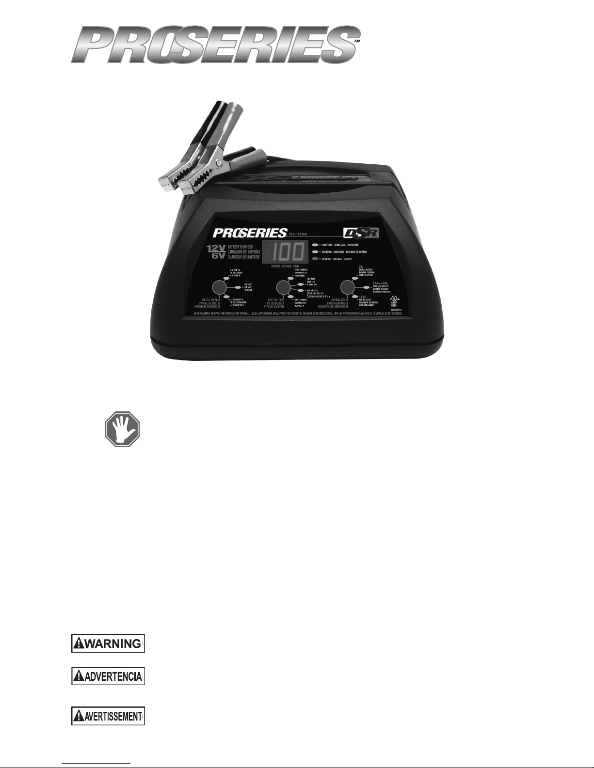
Automatic Battery Charger
Cargador de batería automático
Chargeur de batterie automatique
Model / Modelo / Modèle : PSC-12500A
OWNER’S MANUAL
MANUAL DEL USUARIO
GUIDE D’UTILISATION
DO NOT RETURN THIS PRODUCT TO THE STORE!
Contact Customer Service for assistance:
Phone: 800-621-5485
Email: services@schumacherelectric.com
Web: www.batterychargers.com
¡NO LO DEVUELVA ESTE PRODUCTO A LA TIENDA!
Contacte Servicios al Cliente para asistencia:
Teléfono: 800-621-5485
Correo Electrónico: services@schumacherelectric.com
Sitio Red: www.batterychargers.com
NE PAS RETOURNER LE PRODUIT AU MAGASIN!
Contactez le service clientéle pour l’aide :
Téléphone : 800-621-5485
E-mail : services@schumacherelectric.com
Site web : www.batterychargers.com
READ THE ENTIRE MANUAL BEFORE USING THIS PRODUCT.
FAILURE TO DO SO COULD RESULT IN SERIOUS INJURY OR DEATH.
LEA EL MANUAL COMPLETO ANTES DE UTILIZAR ESTE PRODUCTO.
CUALQUIER FALLA PODRÍA RESULTAR EN SERIAS LESIONES
O PODRÍA SER MORTAL.
LIRE ENTIÈREMENT LE GUIDE AVANT D’UTILISER CE PRODUIT.
L’ÉCHEC DE FAIRE AINSI PEUT S’ENSUIVRE DANS LA BLESSURE
SÉRIEUSE OU LA MORT.
• 2 •
IMPORTANT: READ AND SAVE THIS SAFETY AND INSTRUCTION MANUAL.
SAVE THESE INSTRUCTIONS – This manual will show you how to use your charger safely
and effectively. Please read, understand and follow these instructions and precautions
carefully, as this manual contains important safety and operating instructions. The safety
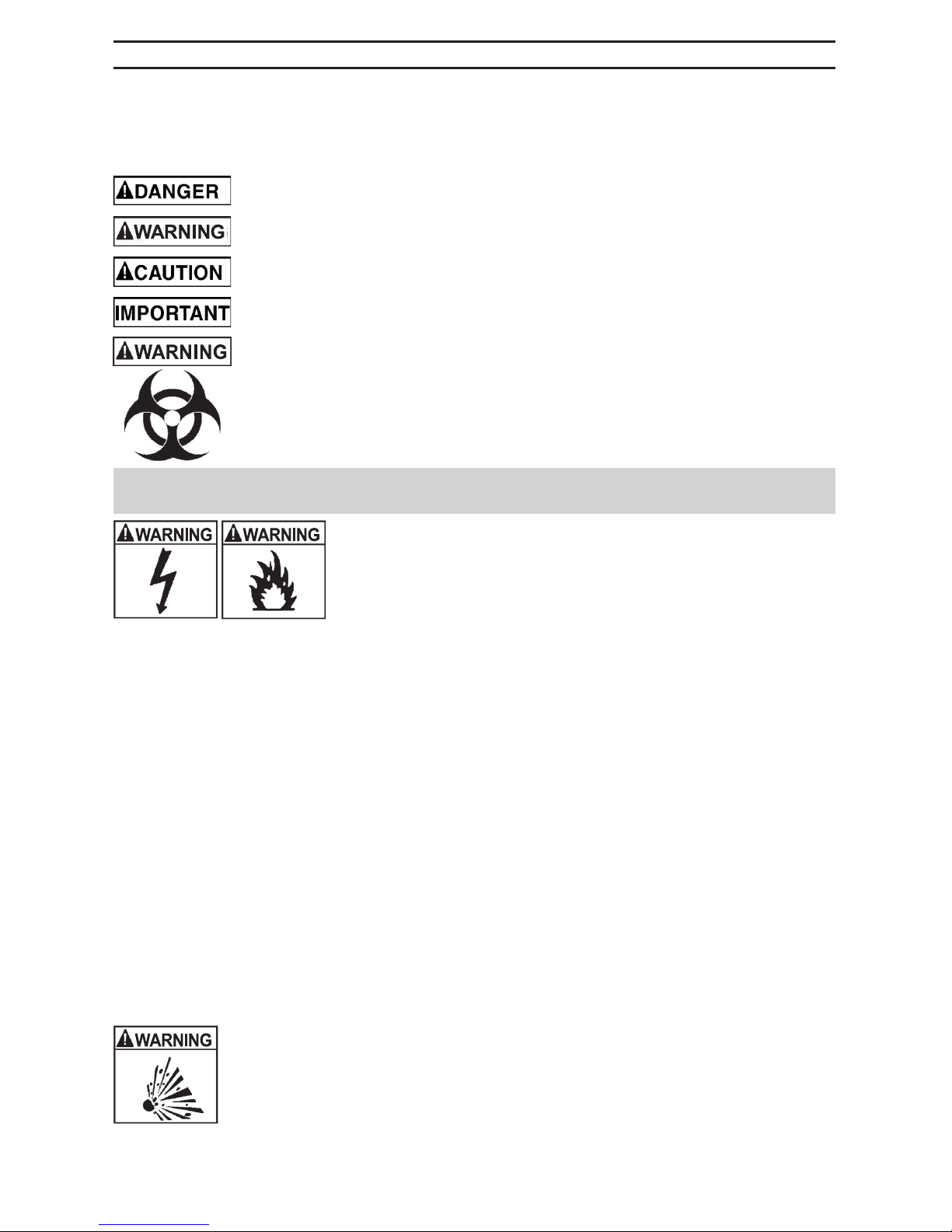
messages used throughout this manual contain a signal word, a message and an icon.
The signal word indicates the level of the hazard in a situation.
Indicates an imminently hazardous situation which, if not avoided, will result in
death or serious injury to the operator or bystanders.
Indicates a potentially hazardous situation which, if not avoided, could result in
death or serious injury to the operator or bystanders.
Indicates a potentially hazardous situation which, if not avoided, could result in
moderate or minor injury to the operator or bystanders.
Indicates a potentially hazardous situation which, if not avoided, could result in
damage to the equipment or vehicle or property damage.
Pursuant to California Proposition 65, this product contains chemicals
known to the State of California to cause cancer and birth defects or other
reproductive harm. Wash hands after handling.
1. IMPORTANT SAFETY INSTRUCTIONS – SAVE THESE INSTRUCTIONS.
This manual contains important safety and operating instructions.
RISK OF ELECTRIC SHOCK OR FIRE.
1.1 Keep out of reach of children.
1.2 Do not expose the charger to rain or snow.
1.3 Use only recommended attachments. Use of an attachment
not recommended or sold by Schumacher® Electric Corporation
may result in a risk of re, electric shock or injury to persons or
damage to property.
1.4 To reduce the risk of damage to the electric plug or cord, pull by the plug rather than the
cord when disconnecting the charger.
1.5 An extension cord should not be used unless absolutely necessary. Use of an improper
extension cord could result in a risk of re and electric shock. If an extension cord must be
used, make sure:
• That the pins on the plug of the extension cord are the same number, size and shape as
those of the plug on the charger.
• That the extension cord is properly wired and in good electrical condition.
• That the wire size is large enough for the AC ampere rating of the charger as specied
in section 8.
1.6 To reduce the risk of electric shock, unplug the charger from the outlet before attempting
any maintenance or cleaning. Simply turning off the controls will not reduce this risk.
1.7 Do not operate the charger with a damaged cord or plug; have the cord or plug replaced
immediately by a qualied service person.
1.8 Do not operate the charger if it has received a sharp blow, been dropped or otherwise
damaged in any way; take it to a qualied service person.
1.9 Do not disassemble the charger; take it to a qualied service person when service or
repair is required. Incorrect reassembly may result in a risk of re or electric shock.
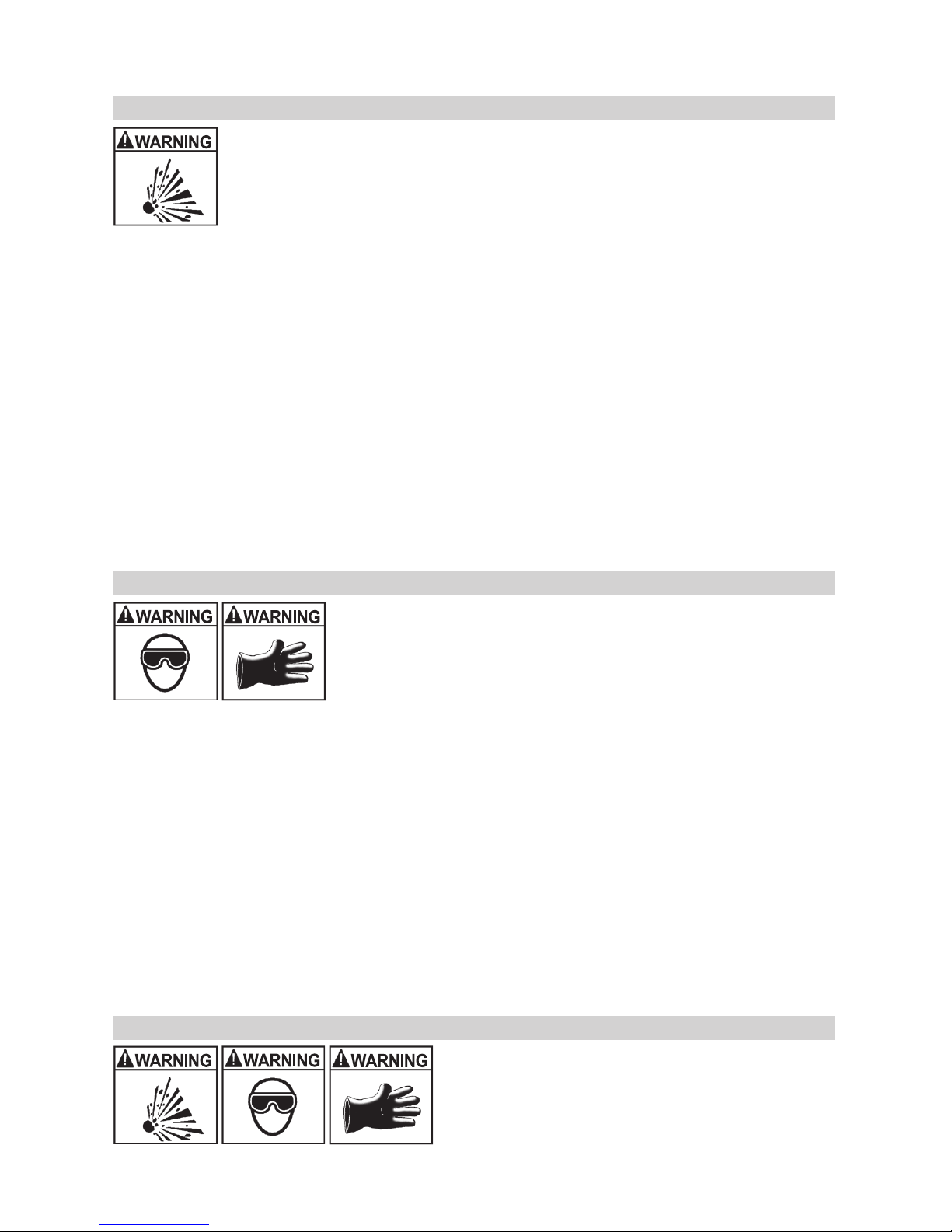
RISK OF EXPLOSIVE GASES.
1.10 WORKING IN THE VICINITY OF A LEAD-ACID BATTERY IS DANGEROUS.
BATTERIES GENERATE EXPLOSIVE GASES DURING NORMAL BATTERY
OPERATION. FOR THIS REASON, IT IS OF UTMOST IMPORTANCE THAT YOU
FOLLOW THE INSTRUCTIONS EACH TIME YOU USE THE CHARGER.
1.11 To reduce the risk of a battery explosion, follow these instructions and
those published by the battery manufacturer and the manufacturer of any equipment
you intend to use in the vicinity of the battery. Review the cautionary markings on these
products and on the engine.
• 3 •
1.12 This charger employs parts, such as switches and circuit breakers, that tend to produce
arcs and sparks. If used in a garage, locate this charger 18 inches (46 cm) or more above
oor level.
2. PERSONAL PRECAUTIONS
RISK OF EXPLOSIVE GASES.
2.1 NEVER smoke or allow a spark or ame in the vicinity of a battery or engine.
2.2 Remove personal metal items such as rings, bracelets, necklaces and watches
when working with a lead-acid battery. A lead-acid battery can produce a short-circuit
current high enough to weld a ring or the like to metal, causing a severe burn.
2.3 Be extra cautious, to reduce the risk of dropping a metal tool onto the battery.
It might spark or short-circuit the battery or other electrical part that may cause an explosion.
2.4 Use this charger for charging LEAD-ACID batteries only. It is not intended to supply power
to a low voltage electrical system other than in a starter-motor application. Do not use this
battery charger for charging dry-cell batteries that are commonly used with home appliances.
These batteries may burst and cause injury to persons and damage to property.
2.5 NEVER charge a frozen battery.
2.6 Consider having someone nearby to come to your aid when you work near a lead-acid battery.
2.7 Have plenty of fresh water and soap nearby, in case battery acid contacts your skin,
clothing or eyes.
2.8 Wear complete eye and body protection, including safety goggles and protective clothing.
Avoid touching your eyes while working near the battery.
2.9 If battery acid contacts your skin or clothing, immediately wash the area with soap and
water. If acid enters your eye, immediately ood the eye with cold running water for at
least 10 minutes and get medical attention right away.
2.10 If battery acid is accidentally swallowed, drink milk, the whites of eggs or water. DO NOT
induce vomiting. Seek medical attention immediately.
3. PREPARING TO CHARGE
RISK OF CONTACT WITH BATTERY ACID. BATTERY ACID IS A
HIGHLY CORROSIVE SULFURIC ACID.
3.1 If it is necessary to remove the battery from the vehicle to
charge it, always remove the grounded terminal rst. Make sure all
of the accessories in the vehicle are off to prevent arcing.
3.2 Be sure the area around the battery is well-ventilated while
the battery is being charged.
3.3 Clean the battery terminals before charging the battery. During cleaning, keep airborne
corrosion from coming into contact with your eyes, nose and mouth. Use baking soda and
water to neutralize the battery acid and help eliminate airborne corrosion. Do not touch
your eyes, nose or mouth.
3.4 Add distilled water to each cell until the battery acid reaches the level specied by the
battery manufacturer. Do not overll. For a battery without removable cell caps, such
as valve regulated lead-acid batteries (VRLA), carefully follow the manufacturer’s
recharging instructions.
3.5 Read, understand and follow all instructions for the charger, battery, vehicle and any
equipment used near the battery and charger. Study all of the battery manufacturer’s
specic precautions while charging and recommended rates of charge.
3.6 Determine the voltage of the battery by referring to the vehicle owner’s manual and make
sure that the output voltage selector switch is set to the correct voltage.
3.7 Make sure that the charger cable clips make tight connections.
4. CHARGER LOCATION
RISK OF EXPLOSION AND CONTACT WITH
BATTERY ACID.
4.1 Locate the charger as far away from the
battery as the DC cables permit.
4.2 Never place the charger directly above the
battery being charged; gases from the battery will
corrode and damage the charger.
• 4 •
4.3 Do not set the battery on top of the charger.
4.4 Never allow battery acid to drip onto the charger when reading the electrolyte specic
gravity or lling the battery.
4.5 Do not operate the charger in a closed-in area or restrict the ventilation in any way.
5. DC CONNECTION PRECAUTIONS
5.1 Connect and disconnect the DC output clips only after removing the AC plug from the
electrical outlet. Never allow the clips to touch each other.
5.2 Attach the clips to the battery and chassis, as indicated in sections 6 and 7.
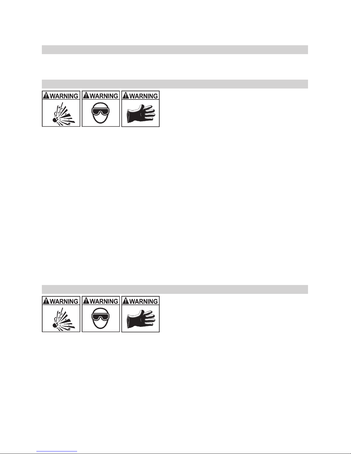
6. FOLLOW THESE STEPS WHEN BATTERY IS INSTALLED IN VEHICLE.
A SPARK NEAR THE BATTERY MAY CAUSE A
BATTERY EXPLOSION. TO REDUCE THE RISK
OF A SPARK NEAR THE BATTERY:
6.1 Position the AC and DC cables to reduce the
risk of damage by the hood, door and moving or hot
engine parts. NOTE: If it is necessary to close the
hood during the charging process, ensure that the hood does not touch the metal part of
the battery clips or cut the insulation of the cables.
6.2 Stay clear of fan blades, belts, pulleys and other parts that can cause injury.
6.3 Check the polarity of the battery posts. The POSITIVE (POS, P, +) battery post usually has
a larger diameter than the NEGATIVE (NEG, N, -) post.
6.4 Determine which post of the battery is grounded (connected) to the chassis. If the negative
post is grounded to the chassis (as in most vehicles), see step 6.5. If the positive post is
grounded to the chassis, see step 6.6.
6.5 For a negative-grounded vehicle, connect the POSITIVE (RED) clip from the battery
charger to the POSITIVE (POS, P, +) ungrounded post of the battery. Connect the
NEGATIVE (BLACK) clip to the vehicle chassis or engine block away from the battery. Do
not connect the clip to the carburetor, fuel lines or sheet-metal body parts. Connect to a
heavy gauge metal part of the frame or engine block.
6.6 For a positive-grounded vehicle, connect the NEGATIVE (BLACK) clip from the battery
charger to the NEGATIVE (NEG, N, -) ungrounded post of the battery. Connect the
POSITIVE (RED) clip to the vehicle chassis or engine block away from the battery. Do not
connect the clip to the carburetor, fuel lines or sheet-metal body parts. Connect to a heavy
gauge metal part of the frame or engine block.
6.7 Connect charger AC supply cord to electrical outlet.
6.8 When disconnecting the charger, turn all switches to off, disconnect the AC cord, remove
the clip from the vehicle chassis and then remove the clip from the battery terminal.
7. FOLLOW THESE STEPS WHEN BATTERY IS OUTSIDE VEHICLE.
A SPARK NEAR THE BATTERY MAY CAUSE A
BATTERY EXPLOSION. TO REDUCE THE RISK
OF A SPARK NEAR THE BATTERY:
7.1 Check the polarity of the battery posts. The
POSITIVE (POS, P, +) battery post usually has a
larger diameter than the NEGATIVE (NEG, N, -) post.
7.2 Attach at least a 24-inch (61 cm) long 6-gauge (AWG) insulated battery cable to the
NEGATIVE (NEG, N, -) battery post.
7.3 Connect the POSITIVE (RED) charger clip to the POSITIVE (POS, P, +) post of the battery.
7.4 Position yourself and the free end of the cable you previously attached to the NEGATIVE
(NEG, N, -) battery post as far away from the battery as possible – then connect the
NEGATIVE (BLACK) charger clip to the free end of the cable.
7.5 Do not face the battery when making the nal connection.
7.6 Connect charger AC supply cord to electrical outlet.
7.7 When disconnecting the charger, always do so in the reverse order of the connecting
procedure and break the rst connection while as far away from the battery as practical.
7.8 A marine (boat) battery must be removed and charged on shore. To charge it onboard
requires equipment specially designed for marine use.
• 5 •
8. GROUNDING AND AC POWER CORD CONNECTIONS
RISK OF ELECTRIC SHOCK OR FIRE.
8.1 This battery charger is for use on a nominal
120-volt circuit and has a grounded plug that
looks like the plug illustrated. The charger must be
grounded to reduce the risk of electric shock. The
plug must be plugged into an outlet that is properly
installed and grounded in accordance with all local codes and ordinances.
The plug pins must t the receptacle (outlet). Do not use with an ungrounded system.
8.2 Never alter the AC cord or plug provided – if it does not t the outlet, have
a proper grounded outlet installed by a qualied electrician. An improper connection can
result in a risk of an electric shock or electrocution. NOTE: Pursuant to Canadian
Regulations, use of an adapter plug is not allowed in Canada. Use of an adapter plug in
the United States is not recommended and should not be used.
8.3 Recommended minimum AWG size for extension cord:
• 100 feet (30.5 meters) long or less – use a 16 gauge (1.31 mm2) extension cord.
• Over 100 feet (30.5 meters) long – use a 14 gauge (2.08 mm2) extension cord.
9. ASSEMBLY INSTRUCTIONS
Included with your charger are two cord wrap cleats for storage of the clip cables.
9.1 To install, align the two tabs with the two receptacles and push until you hear a snap.
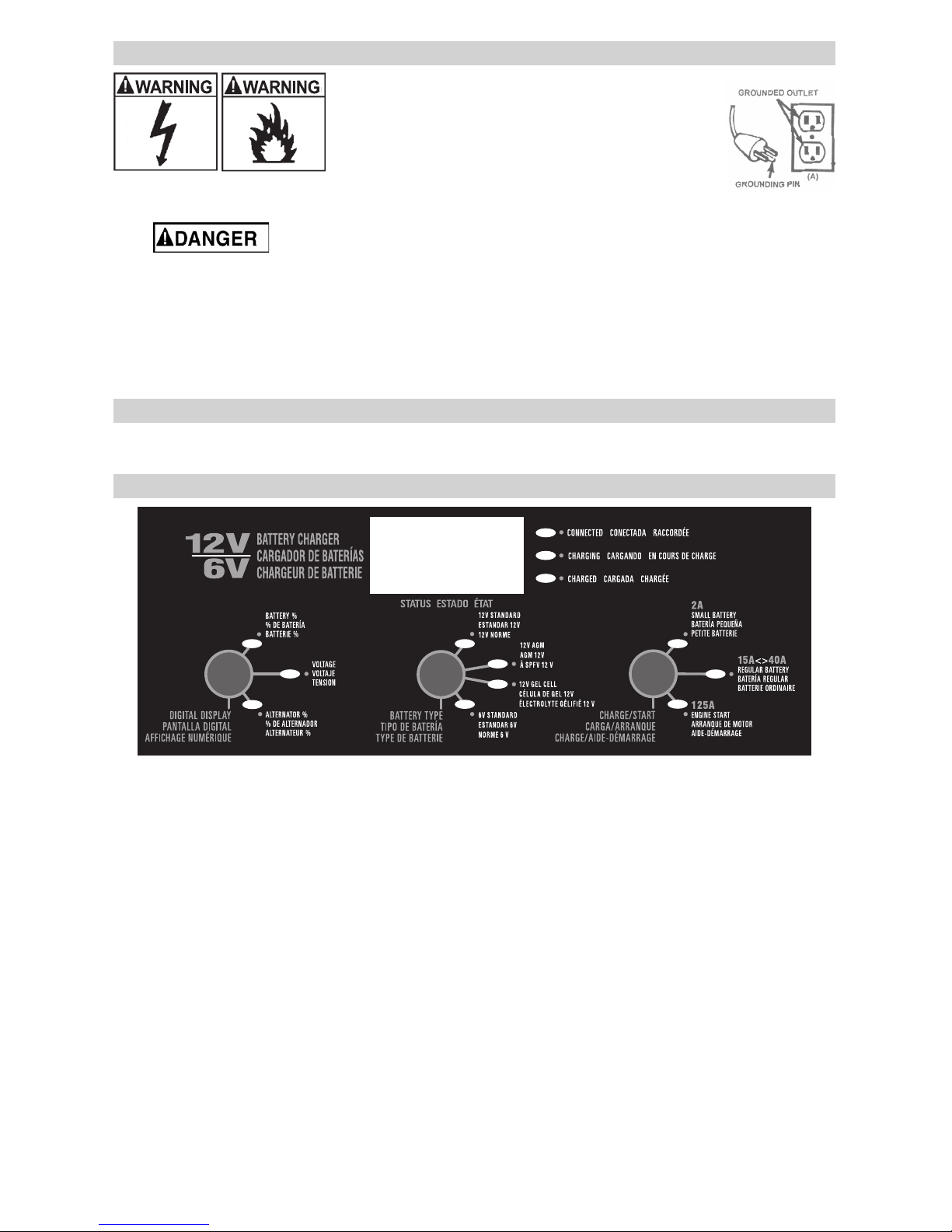
10. CONTROL PANEL
Digital Display
The Digital Display gives a digital indication of voltage, % of charge or alternator output %,
depending on the Display Mode chosen.
Display Mode Button
Use this button to set the function of the digital display to one of the following:
• Battery % – The digital display shows an estimated charge percentage of the battery
connected to the charger battery clips.
• Voltage – The digital display shows the voltage at the charger battery clips in DC volts.
• Alternator % – The digital display shows an estimated output percentage of the
vehicle’s charging system connected to the charger battery clips as compared to a
properly functioning system.
Battery Type Button
Use this button to set the type of battery to be charged.
• Standard – Set the button to STANDARD. Used in cars, boats, trucks and motorcycles,
these batteries have vent caps for adding distilled water as needed, and are often
marked “Low Maintenance” or “Maintenance-free”.
• AGM (Absorbed Glass Mat) – Set the button to AGM. These batteries have electrolyte
absorbed in separators consisting of a sponge-like mass of matted glass ber. AGM
batteries are sealed with special pressure valves and should not be opened.
• GEL – Set the button to GEL CELL. These batteries contain gelled electrolytes. They
are sealed with valves and should not be opened.

• 6 •
NOTE: When charging a battery that is not marked, check the manual of the item which
uses the battery for the correct battery type. Make sure the battery complies with the
safety instructions in Section 2.4.
Charge Rate Button
Use the Charge Rate button to select the charge rate or engine starting setting you require.
• SMALL BATTERY – Provides a charge rate of up to 2A. Intended for charging small
batteries such as those commonly used in garden tractors, snowmobiles and motorcycles.
NOTE: The 2A rate is not to be used as a trickle charger for larger batteries.
• REGULAR BATTERY – Automatically switches between the 15A and 40A variable charge
rate or charges continuously at the 15A rate, depending on the battery. Use for charging
automotive, marine and deep-cycle batteries. Not intended for industrial applications.
• ENGINE START – Used for cranking an engine with a weak or run-down battery. Always
use in combination with a battery.
11. OPERATING INSTRUCTIONS
Charging
1. Connect the battery following the precautions listed in Sections 6 and 7.
2. Connect the AC power following the precautions listed in Section 8.
3. Select the appropriate settings for your battery.
NOTE: Pressing any button while charging will stop the charging process and the Digital
Display will read Off.
Battery Connection Indicator
If the charger does not detect a properly connected battery, the CONNECTED (yellow)
LED will not light until such a battery is detected. Charging will not begin while the
CONNECTED (yellow) LED is not on. When charging begins, the CHARGING (yellow)
LED will illuminate.
Automatic Charging Mode
When an Automatic Charge is performed, the charger switches to the Maintain Mode (see
below) automatically after the battery is charged. NOTE: The battery must have at least a
0.1 volt charge in order for the microprocessor to analyze and begin the charging process.
Aborted Charge
If charging can not be completed normally, charging will abort. When charging aborts, the
charger’s output is shut off. The CONNECTED (yellow) LED will remain lit, and the Digital
Display will read bad bat. In that state, the charger ignores all buttons. To reset after an
aborted charge, either disconnect the battery or unplug the charger.
Desulfation Mode
If the battery is left discharged for an extended period of time, it could become sulfated
and not accept a normal charge. If the charger detects a sulfated battery, the charger will
switch to a special mode of operation designed for such batteries. Activation of the special
Desulfation Mode is indicated by the CHARGING (yellow) LED blinking. If successful,
normal charging will resume after the battery is desulfated. The CHARGING (yellow) LED
will then stop blinking and stay lit. Desulfation could take up to 10 hours. If desulfation
fails, charging will abort. The CONNECTED (yellow) LED will remain lit, and the Digital
Display will read bad bat.
Completion of Charge
Charge completion is indicated by the CHARGED (green) LED. When lit, the charger has
stopped charging and switched to the Maintain Mode of operation.
Maintain Mode
When the CHARGED (green) LED is lit, the charger has started Maintain Mode. In this
mode, the charger keeps the battery fully charged by delivering a small current when
necessary. If the battery voltage drops below a preset level the charger will go back into
Charge Mode until the battery voltage returns to the full charge level, at which point the
charger will return to Maintain Mode. The voltage is maintained at a level determined by
the BATTERY TYPE selected.
NOTE: The charger automatically switches between Charge Mode and Maintain Mode as
necessary. The CHARGED (green) LED will cycle on when the battery is at full charge and
off when the voltage drops below a preset level and the charger goes into Charge Mode.
This cycle will continue, and the CHARGED (green) LED will stay on for longer periods of
time as the battery becomes more fully charged.

• 7 •
Using the Engine Start feature
Your battery charger can be used to jumpstart your car if the battery is low. Follow these
instructions on how to use the ENGINE START feature.
IMPORTANT: Follow all safety instructions and precautions for charging your battery.
Wear complete eye protection and clothing protection. Charge your battery in a wellventilated area.
IMPORTANT: Using the ENGINE START feature WITHOUT a battery installed in the
vehicle could cause damage to the vehicle’s electrical system.
1. With the charger unplugged from the AC outlet, connect the charger to the battery
following the instructions given in Section 6.
2. Plug the charger AC power cord into the AC outlet.
3. With the charger plugged in and connected to the battery of the vehicle, set the Battery
Size Button to the engine start position.
4. Crank the engine until it starts or 5 seconds pass. If the engine does not start, wait 3
minutes before cranking again.
NOTE: During extremely cold weather, or if the battery is under 2 volts, charge the battery
for 5 minutes before cranking the engine.
5. If the engine fails to start, charge the battery for 5 more minutes before attempting to
crank the engine again.
6. After the engine starts, unplug the AC power cord before disconnecting the battery
clips from the vehicle.
7. Clean and store the charger in a dry location.
NOTE: If the engine does turn over, but never starts, there is not a problem with the
starting system; there is a problem somewhere else with the vehicle. STOP cranking the
engine until the other problem has been diagnosed and corrected.
Engine Starting Notes
During the starting sequence listed above, the charger is set to one of three states:
Wait for cranking – The charger waits until the engine is actually being cranked before
delivering the required amps for engine start. The charger delivers charge at a preset rate
while waiting and will reset if the engine is not cranked within 15 minutes. (If the charger
resets, it sets itself to the default start up settings). While waiting for cranking, the digital
display shows the battery voltage (it cannot be set to percent).
Cranking – When cranking is detected, the charger will automatically deliver up to its
maximum output as required by the starting system for up to 5 seconds or until the engine
cranking stops. The digital display shows a countdown of the remaining crank time in
seconds. It starts at 5 and counts down to 0.
Cool Down – After cranking, the charger enters a mandatory 3 minute (180 second) cool
down state. During this period, no settings can be changed. The buttons are ignored.
The digital display indicates the remaining cool down time in seconds. It starts at 180 and
counts down to 0. The ENGINE START LED blinks once every second. During the cool
down period, no current is delivered to the battery. After 3 minutes, the ENGINE START
LED will stop blinking and will light continuously, indicating that another crank cycle can be
started. The digital display will change from displaying the countdown back to displaying
the battery voltage. The CHARGING (yellow) LED will then be lit.
Using the Battery Voltage Tester
Overview
This battery charger has a built-in voltmeter to test your battery’s state of charge. The
charger does not have a built in load tester. As such, a recently charged battery could have
a temporarily high voltage due to what is known as “surface charge”. The voltage of such
a battery will gradually drop during the period immediately after the charging system is
disengaged. Consequently, the tester could display inconsistent values for such a battery. For
a more accurate reading, the surface charge should be removed by temporarily creating a
load on the battery, such as by turning on lights or other accessories for a couple of minutes
before you read the display. Read it a couple of minutes after you have shut the headlights off.
Testing Sequence: There are four basic steps required to test the battery state of charge:
1. With the charger unplugged from the AC outlet, connect the charger to the battery
following the instructions given in Sections 6 and 7.
2. Plug the charger AC power cord into the AC outlet, following the instructions given in
Section 8.

• 8 •
3. If necessary, press the BATTERY TYPE button until the correct type is indicated.
4. Read the voltage on the digital display or press the Display Mode button to set the
tester to BATTERY % to read the voltage as a percent of charge.
Tester and Charger: When rst turned on, the unit operates only as a tester, not as a
charger. To continue to use it only as a tester, avoid pressing the BATTERY SIZE button.
Selecting a charge rate activates the battery charger and deactivates the tester. Pressing
the BATTERY SIZE button when the ENGINE START LED is lit (except during the 180
second cool down) will shut off the charger and activate the tester.
Power-Up Idle Time Limit: If no button is pressed within 15 minutes after the battery
charger is rst powered up, the charger will automatically switch from tester to charger if a
battery is connected. In that case, the charger will be set to the start up default settings.
Tester without Time Limit: If either the DISPLAY MODE or BATTERY TYPE button is
pressed within the rst 10 minutes after the battery charger is powered up, the unit will
remain a tester (not a charger) indenitely, unless a charge rate is selected.
Testing After Charging: After the unit has been changed from tester to charger (by
selecting a charge rate), it remains a charger. To change the battery charger back to a
tester, press the BATTERY SIZE button until all charge rate LEDs are off.
Tester Status LEDs: When the unit is operating as a battery tester, the status LEDs light
under the following conditions:
• The CHARGED (green) LED will light if a charged battery is tested.
• The CHARGING (yellow) LED does not light in the Battery Test Mode.
• The CONNECTED (yellow) LED will light if a properly connected battery is detected.
Initial Percent Calculation: When a battery % is calculated for the rst time after
connecting a battery, the digital display will show three dashes (“---”) for a period as long
as several seconds while the tester analyzes the battery.
Using the Alternator Performance Tester
Overview
This battery charger has a built-in alternator tester that displays an estimate of the alternator’s
relative output compared to normal alternators. The alternator % values displayed should be
taken as a general reference, not a precise diagnosis. The alternator tester functions the same
as the built-in battery voltage tester (see previous section for details) with a few differences.
Testing Sequence: There are three basic steps required to operate this unit as an
alternator tester:
1. With the charger unplugged from the AC outlet, connect the charger to the battery
following the instructions given in Sections 6 and 7.
2. Plug the charger AC power cord into the AC outlet, following the instructions given in
Section 8.
3. Start the vehicle, and turn on the vehicle’s headlights. Read the voltage on the digital
display or press the DISPLAY MODE button to set the tester to ALTERNATOR % to
read the voltage as a percent of charge.
Alternator Testing Note: The DISPLAY MODE cannot be set to ALTERNATOR %
during charging.
General Charging Notes
Fan: The charger is designed to control its cooling fan for efcient operation. It is normal
for the fan to start and stop when maintaining a fully charged battery. The fan does not run
in Tester Mode. Keep the area near the charger clear of obstructions to allow the fan to
operate efciently.
Restart: If the Charge Mode is changed after charging has started (by pressing the
BATTERY SIZE or BATTERY TYPE button), the charging process will restart.
Voltage: The voltage displayed during charging is the charging voltage and is usually
higher than the battery’s resting voltage.
Charging Tips
Read this entire manual before using your battery charger. The following tips serve only as
a guide for specic situations.
• If your vehicle won’t start – It is not necessary to fully charge your battery to start
a vehicle. When the battery’s charge is 77% or more, the battery has usually been
charged enough for the vehicle to start and operate normally. If operating the vehicle
continuously for an extended period (such as a long drive), the vehicle’s charging

• 9 •
system should charge the battery back to normal during that period. If the vehicle will
only be operated for a short period (short drive), the battery might need to be charged
again before it could start the vehicle again.
• Completing an interrupted charge – Once the battery has reached 85% charge, if the
charging process is interrupted and restarted, the charger could go straight into Maintain
Mode. However, if the original charge was started using the 15◄►40A rate, the charge
can often be completed using the 2A rate.
12. MAINTENANCE INSTRUCTIONS
12.1 Before performing maintenance, unplug and disconnect the battery charger
(see Sections 6, 7 and 8).
12.2 After use, unplug the charger and use a dry cloth to wipe all battery corrosion and other
dirt or oil from the terminals, cords, and the charger case.
12.3 Servicing does not require opening the unit, as there are no user-serviceable parts.
13. STORAGE INSTRUCTIONS
13.1 Store the charger unplugged, in an upright position. The cord will still conduct electricity
until it is unplugged from the outlet.
13.2 Store inside, in a cool, dry place (unless you’re using an on-board Marine Charger).
13.3 Do not store the clips on the handle, clipped together, on or around metal, or clipped to cables.
14. TROUBLESHOOTING
PROBLEM POSSIBLE CAUSE REASON/SOLUTION
The charger is
making an audible
clicking sound.
Circuit breaker is cycling.
Battery is defective.
Shorted battery cables or clips.
Severely discharged battery, but
otherwise it is a good battery.
Reverse connections at battery.
The settings may be wrong.
Check the charger settings.
Have the battery checked.
Circuit breaker is cycling. Check
for shorted cables or clips and
replace if necessary.
Allow charging to continue until
battery has a chance to recover
sufciently to take a charge.
If more than 20 minutes, stop
charging and have the battery
checked.
Shut the charger off and correct
the lead connections.
Charger makes a loud
buzz or hum.
Transformer laminations vibrate
(buzz).
Shorted Diode Assembly or
Output Rectier Assembly (hum).
No problem; this is a normal
condition.
Have charger checked by a
qualied technician.

• 10 •
PROBLEM POSSIBLE CAUSE REASON/SOLUTION
Short or no start
cycle when cranking
engine.
Drawing more amps than the
charger can provide.
Failure to wait 3 minutes
(180 seconds) between cranks.
Clips are not making a good
connection.
AC cord and/or extension cord
is loose.
No power at receptacle.
The charger may be overheated.
Battery may be severely
discharged.
Crank time varies with the
amount of current drawn. If
cranking draws more amps than
the charger can provide, crank
time may be less than 3 seconds.
Wait 3 minutes of rest time
before the next crank.
Check for poor connection at
battery and frame.
Check power cord and extension
cord for loose tting plug.
Check for open fuse or circuit
breaker supplying AC outlet.
The thermal protector may have
tripped and needs a little longer
to reset. Make sure the charger
vents are not blocked. Wait and
try again.
On a severely discharged
battery, charge for 10 to 15
minutes in the highest charge
rate to help assist in cranking.
Charger will not turn
on when properly
connected.
AC outlet is dead.
Poor electrical connection.
Check for open fuse or circuit
breaker supplying AC outlet.
Check power cord and extension
cord for loose tting plug.
The battery is
connected and the
charger is on, but is
not charging.
Clips are not making a good
connection.
The charger is in tester mode,
not charge mode.
Check for poor connection at
battery and frame. Make sure
connecting points are clean.
Rock clips back and forth for a
better connection.
Press the Charge Rate button to
activate charging and select a
charge rate.
The measured current
is much lower than
what was selected.
The charger reached the
maximum voltage and is
reducing the current.
No problem; this is a normal
condition.
The DIGITAL
DISPLAY always
ashes before the
battery is completely
charged.
The incorrect BATTERY TYPE
may have been selected.
The battery did not reach full
charge within 24 hours.
The battery is defective.
Reset the charger by briey
unplugging it or briey
disconnecting the negative
battery clip. Be sure to reset the
charger to the proper settings.
May be due to a very large battery
or bank of batteries requiring more
power than the charger can deliver
within 24 hours.
Have the battery checked.

• 11 •
PROBLEM POSSIBLE CAUSE REASON/SOLUTION
The CHARGED
(green) LED lights
a few minutes after
connecting to the
battery.
The battery may be fully charged
or recently charged, leaving the
battery voltage high enough to
appear to be fully charged.
The incorrect BATTERY TYPE
may have been selected.
If the battery is in a vehicle,
turn the headlights on for a few
minutes to reduce the battery
voltage and try charging again.
Reset the charger by briey
unplugging it or briey
disconnecting the negative
battery clip. Be sure to reset the
charger to the proper settings.
The indicator lights
are lit in an erratic
manner not explained
in this manual.
You might have accidentally
activated a special diagnostic
mode.
Make sure nothing is touching
the control panel, then unplug
the charger and plug it in again.
15. BEFORE RETURNING FOR REPAIRS
15.1 When a charging problem arises, make certain that the battery is capable of accepting
a normal charge. Use a good battery to double check all connections, AC outlet for a full
120-volts, charger clips for correct polarity and the quality of the connections from the
cables to the clips and from the clips to the battery system. The clips must be clean.
15.2 When a battery is very cold, partially charged or sulfated, it will not draw the full rated
amperes from the charger. It is both dangerous and damaging to a battery to force higher
amperage into it than it can effectively use in recharging.
15.3 When an UNKNOWN OPERATING PROBLEM arises, please read the complete manual
and call the customer service number for information. This will usually eliminate the need
for return.
If the above solutions do not eliminate the problem,
or for information about troubleshooting or replacement parts,
call toll-free from anywhere in the U.S.A.
1-800-621-5485
7:00 am to 5:00 pm Central Time Monday thru Friday
For REPAIR OR RETURN, contact Customer Service at 1-800-621-5485.
DO NOT SHIP UNIT until you receive RETURN AUTHORIZATION
from Customer Service at Schumacher Electric Corporation.

• 12 •
16. LIMITED WARRANTY
SCHUMACHER ELECTRIC CORPORATION, 801 BUSINESS CENTER DRIVE, MOUNT
PROSPECT, IL 60056-2179, MAKES THIS LIMITED WARRANTY TO THE ORIGINAL
RETAIL PURCHASER OF THIS PRODUCT. THIS LIMITED WARRANTY
IS NOT TRANSFERABLE OR ASSIGNABLE.
Schumacher Electric Corporation (the “Manufacturer”) warrants this battery charger for 5
years from the date of purchase at retail against defective material or workmanship that
may occur under normal use and care. If your unit is not free from defective material or
workmanship, Manufacturers obligation under this warranty is solely to repair or replace
your product, with a new or reconditioned unit, at the option of the Manufacturer. It is the
obligation of the purchaser to forward the unit, along with proof of purchase and mailing
charges prepaid to the Manufacturer or its authorized representatives in order for repair or
replacement to occur.
Manufacturer does not provide any warranty for any accessories used with this product
that are not manufactured by Schumacher Electric Corporation and approved for use with
this product. This Limited Warranty is void if the product is misused, subjected to careless
handling, repaired, or modied by anyone other than Manufacturer or if this unit is resold
through an unauthorized retailer.
Manufacturer makes no other warranties, including, but not limited to, express, implied or
statutory warranties, including without limitation, any implied warranty of merchantability
or implied warranty of tness for a particular purpose. Further, Manufacturer shall not be
liable for any incidental, special or consequential damage claims incurred by purchasers,
users or others associated with this product, including, but not limited to, lost prots,
revenues, anticipated sales, business opportunities, goodwill, business interruption and
any other injury or damage. Any and all such warranties, other than the limited warranty
included herein, are hereby expressly disclaimed and excluded. Some states do not allow
the exclusion or limitation of incidental or consequential damages or length of implied
warranty, so the above limitations or exclusions may not apply to you. This warranty gives
you specic legal rights and it is possible you may have other rights which vary from this
warranty.
THIS LIMITED WARRANTY IS THE ONLY EXPRESS LIMITED WARRANTY AND THE
MANUFACTURER NEITHER ASSUMES OR AUTHORIZES ANYONE TO ASSUME OR
MAKE ANY OTHER OBLIGATION TOWARDS THE PRODUCT OTHER THAN THIS
WARRANTY.
Schumacher Electric Corporation Customer Service
1-800-621-5485
Monday – Friday 7:00 a.m. to 5:00 p.m. CST
Schumacher® and the Schumacher Logo are registered trademarks
of Schumacher Electric Corporation.
DO NOT RETURN THIS PRODUCT TO THE STORE!
Contact Customer Service for assistance:
Phone: 800-621-5485
Email: services@schumacherelectric.com
Web: www.batterychargers.com
 Loading...