

0099001110-01
OWNERS MANUAL
GUIDE D’UTILISATION
Model / Modèle :
PIF-1000
Power Inverter
Converts 12V DC Battery Power to AC Household Power
Onduleur de puissance
Convertit la tension d’une batterie 12V CC à pouvoir domestique CA
PLEASE SAVE THIS OWNERS MANUAL AND READ BEFORE EACH USE.
This manual will explain how to use the converter safely and effectively. Please
read and follow these instructions and precautions carefully.
ESSAYER DE GARDER LE MANUEL D’INSTRUCTIONS ET LE LIRE AVANT
CHAQUE UTILISATION. Ce manuel explique comment utiliser l’unité d’une façon
sûre et efcace. S’il vous plaît lisez et suivez ces instructions et précautions.

CONTENTS
IMPORTANT SAFETY INSTRUCTIONS ............................................................................. 4
INVERTER FEATURES ........................................................................................................ 5
BEFORE USING YOUR POWER INVERTER ..................................................................... 5
FASTENING THE INVERTER TO A FLAT SURFACE .......................................................... 6
CONNECTING INVERTER CABLES ................................................................................... 6
OPERATING INSTRUCTIONS ............................................................................................. 7
POWER SOURCE ................................................................................................................ 8
LED INDICATOR AND SHUTDOWN PROTECTION ........................................................... 8
LED DISPLAY ....................................................................................................................... 8
IF THE INVERTER FUSE BLOWS ....................................................................................... 9
MAINTENANCE INSTRUCTIONS........................................................................................ 9
TROUBLESHOOTING.......................................................................................................... 9
ACCESSORIES .................................................................................................................... 9
BEFORE RETURNING FOR REPAIRS ............................................................................... 9
SPECIFICATIONS .............................................................................................................. 10
LIMITED WARRANTY ........................................................................................................10
WARRANTY CARD ...........................................................................................................19

TABLE DES MATIÈRES
INSTRUCTIONS IMPORTANTES CONCERNANT LA SÉCURITÉ .................................. 11
CARACTÉRISTIQUES DE L’ONDULEUR .........................................................................12
AVANT D’UTILISER VOTRE ONDULEUR ........................................................................ 12
FIXATION DE L’ONDULEUR SUR UNE SURFACE PLATE ..............................................13
CONNEXION DES CÀBLES DE L’ONDULEUR ................................................................13
INSTRUCTIONS D’UTILISATION ..................................................................................... 14
SOURCE D’ALIMENTATION .............................................................................................. 15
VOYANT DEL ET PROTECTION EN CAS D’ARRÊT ........................................................ 15
AFFICHAGE À DEL ............................................................................................................ 16
SI LE FUSIBLE DE L’ONDULEUR SAUTE ........................................................................ 16
CONSIGNES D’ENTRETIEN ............................................................................................. 16
DÉPANNAGE ..................................................................................................................... 17
ACCESSOIRES .................................................................................................................. 17
AVANT DE L’ENVOYER POUR RÉPARATIONS ............................................................... 17
CARACTÉRISTIQUES ....................................................................................................... 17
GARANTIE LIMITÉE .......................................................................................................... 18
CARTE DE GARANTIE ...................................................................................................... 19
• 4 •
IMPORTANT: READ AND SAVE THIS SAFETY AND INSTRUCTION MANUAL.
SAVE THESE INSTRUCTIONS – The PIF-1000 offers a wide range of features to
accommodate your needs. This manual will show you how to use your inverter safely and
effectively. Please read, understand and follow these instructions and precautions carefully,
as this manual contains important safety and operating instructions. The safety messages
used throughout this manual contain a signal word, a message and an icon.
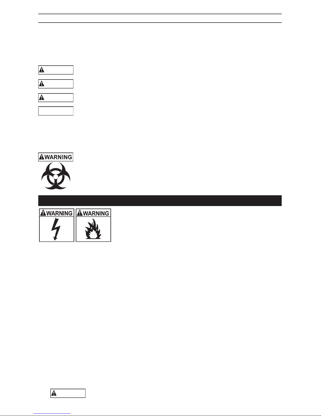
The signal word indicates the level of the hazard in a situation.
Indicates an imminently hazardous situation which, if not avoided, will result in
death or serious injury to the operator or bystanders.
Indicates a potentially hazardous situation which, if not avoided, could result in
death or serious injury to the operator or bystanders.
Indicates a potentially hazardous situation which, if not avoided, could result in
moderate or minor injury to the operator or bystanders.
Indicates a potentially hazardous situation which, if not avoided, could result in
damage to the equipment or vehicle or property damage.
Safety messages in this manual contain two different type styles.
• Unnumbered type states the hazard.
• Numbered type states how to avoid the hazard.
The icon gives a graphical description of the potential hazard.
California Proposition 65 Warning:
WARNING: This Product contains chemicals known to the State of California
to cause cancer and birth defects or other reproductive harm (California law
requires this warning to be given to customers in the State of California).
Wash hands after handling.
1. IMPORTANT SAFETY INSTRUCTIONS – SAVE THESE INSTRUCTIONS.
RISK OF ELECTRIC SHOCK OR FIRE.
1.1 Keep out of reach of children.
1.2 Keep the inverter well ventilated in order to properly disperse
heat generated while it is in use. Make sure there are several
inches of clearance around the top and sides and do not block the
slots of the inverter.
1.3 Make sure the inverter is not close to any potential source of ammable fumes, gases or
clothing.
1.4 Do not place the inverter in areas such as battery compartments or engine compartments
where fumes or gases may accumulate.
1.5 Keep the inverter dry.
1.6 DO NOT allow the inverter to come into contact with rain or moisture.
1.7 DO NOT operate the inverter if you, the inverter, the device being operated or any other
surfaces that may come into contact with any power source are wet. Water and many other
liquids can conduct electricity, which may lead to serious injury or death.
1.8 Do not place the inverter on or near heating vents, radiators or other sources of heat or
ammable materials.
1.9 Do not place the inverter in direct sunlight. The ideal air temperature for operation is
between 50° and 80°F (10º and 27ºC).
1.10 Only connect the power inverter to a 12 volt battery or power supply. Do not attempt to
connect the inverter to any other power source, including an AC power source. Connecting
to a 6 volt or 16 volt battery will cause damage to the inverter.
1.11 Make sure the AC plug is tight.
1.12 Do not modify the inverter in any way including cables, plugs, switches or AC receptacles
as it may result in property damage or personal injury.
1.13 Incorrect operation of the inverter may result in property damage or personal injury.
WARNING
The inverter output is 110V AC and can shock or electrocute the same as
any ordinary household AC wall outlet.
DANGER
WARNING
CAUTION
IMPORTANT
• 5 •
1.14 Do not open – No user serviceable parts inside.
1.15 This device does not include an internal Ground Fault Circuit Interrupter (GFCI).
1.16 To reduce the risk of electric shock, disconnect the inverter from the power source before
attempting any maintenance or cleaning. Simply turning off the controls will not reduce this risk.
1.17 Do not operate the inverter with damaged cables; have the cables replaced immediately by
a qualied service person.
1.18 Do not operate the inverter if it has received a sharp blow, been dropped or otherwise
damaged in any way; take it to a qualied service person.
1.19 Do not disassemble the inverter; take it to a qualied service person when service or repair
is required. Incorrect reassembly may result in a risk of re or electric shock.
1.20 Working in the vicinity of a lead-acid battery is dangerous. Batteries generate explosive
gases during normal battery operation. For this reason, it is of utmost importance that you
follow the instructions each time you use the inverter.
1.21 This inverter employs parts, such as switches and circuit breakers, that tend to produce
arcs and sparks. If used in a garage, locate this inverter 18 inches (46 cm) or more above
the oor level.
1.22 Do not use the inverter with a product that draws a higher wattage than the inverter can
provide, as this may cause damage to the inverter and product.
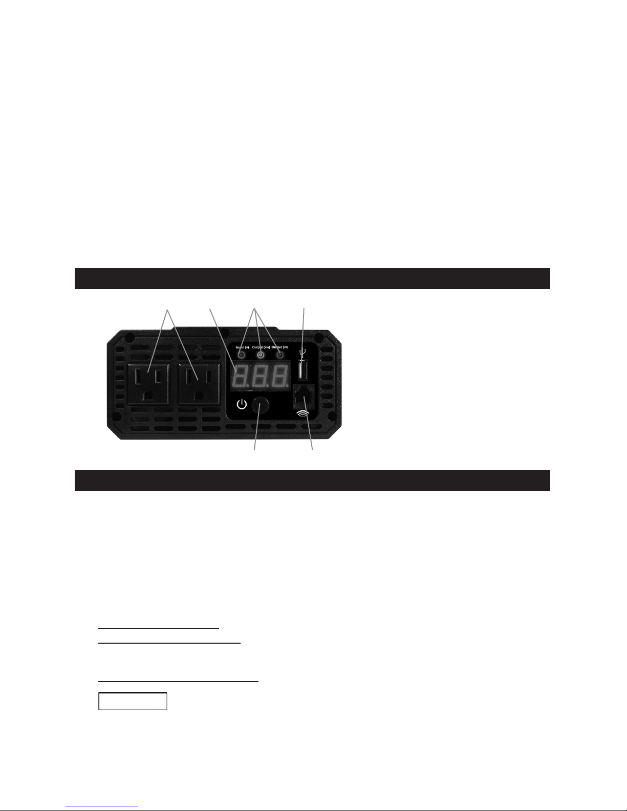
2. INVERTER FEATURES
1. AC outlets
2. Digital display
3. LED Indicators (green):
• DC input voltage
• Output wattage (kW)
• Output wattage (W)
4. USB port
5. ON/OFF button
6. Remote control port
(Remote control sold separately)
5
2 3
1 4
6
3. BEFORE USING YOUR POWER INVERTER
NOTE: Do not use the inverter with a product that draws a higher wattage than the inverter
can provide, as this may cause damage to the inverter and product.
When you turn on a device or a tool that runs on a motor, the device goes through two stages:
1. Start Up – Requiring an initial surge of power (commonly known as the “starting” or
“peak” load).
2. Continuous Operation – Power consumption drops (commonly known as “continuous load”).
The wattage (WATTS) or amperes (AMPS) can normally be found stamped or printed on
most devices and equipment, or in the user’s manual. Otherwise, contact the manufacturer
to nd out whether the device you want to use is compatible with a modied sine wave.
To calculate the wattage: Wattage = AMPS x 110 (AC Voltage).
To calculate the starting load: Starting Load = 2 x WATTS. In general, the start up load
of the device or power tool determines whether or not your inverter has the capability to
power it.
To calculate the continuous load: Continuous Load = AMPS x 110 (AC Voltage).
IMPORTANT
Always run a test to establish whether or not the inverter will operate a
particular piece of equipment or device. In the event of a power overload,
the inverter is designed to automatically shut down. This safety feature prevents damaging
the inverter while testing devices and equipment within the wattage range of the inverter.
If a device does not operate properly when rst connected to the inverter, turn the inverter On/
Off switch ON, OFF, and ON again in quick succession. If this procedure is not successful, it is
likely that the inverter does not have the required capacity to operate the device in question.

• 6 •
IMPORTANT
This inverter uses a nonsinusoidal waveform. Using it with certain devices
may cause the device to run warmer or overheat. Therefore, we do not
recommend you use it to power the following devices:
1. Switch mode power supplies
2. Linear power supplies
3. Class 2 transformers
4. Line lter capacitors
5. Shaded pole motors
6. Fan motors
7. Microwave ovens
8. Fluorescent and high intensity lamps (with a ballast)
9. Transformerless battery chargers
4. FASTENING THE INVERTER TO A FLAT SURFACE
For your convenience, the inverter can be fastened to a at surface, horizontally or
vertically. The area where the inverter is to be fastened must be dry, well ventilated and
away from any combustible material or fumes.
1. Turn off and disconnect the inverter.
2. Place the back of the inverter with the mounting bracket against a at, secure surface.
3. Attach the inverter to the at surface using corrosion-resistant screws.
5. CONNECTING INVERTER CABLES
The inverter and power source must be in the OFF mode.
IMPORTANT
Make sure to connect the inverter to a 12 volt power supply only.
Inverter Connection:
1. Locate the positive and negative plastic terminals located on the right side of the inverter.
2. Remove the red positive (+) plastic cover by squeezing the two ridged areas.
3. Remove the nut and bolt from the terminal.
4. Slide the red protective cover over the red cable in the correct orientation.
5. Using the nut and bolt you removed, attach the red cable to the positive (+) terminal.
Tighten the terminal so that the cable cannot come loose but do not over-tighten.
6. Remove the black negative (-) plastic cover by squeezing the two ridged areas.
7. Remove the nut and bolt from the terminal.
8. Slide the black protective cover over the black cable in the correct orientation.
9. Using the nut and bolt you removed, attach the black cable to the negative (-) terminal.
Tighten the terminal so that the cable cannot come loose but do not overtighten.
Connecting Inverter Cable to 12V Battery or 12V Power Source:
RISK OF CONTACT WITH BATTERY ACID.
BATTERY ACID IS A HIGHLY CORROSIVE
SULFURIC ACID.
A SPARK NEAR THE BATTERY MAY CAUSE A BATTERY EXPLOSION.
TO REDUCE THE RISK OF A SPARK NEAR THE BATTERY:
1. Keep hands, hair, clothing and jewelry clear of battery terminals.
2. Wear eye protection and clothing protection.
3. For a negative-grounded vehicle, connect the POSITIVE (RED) terminal from
the inverter to the POSITIVE (POS, P, +) ungrounded post of the battery. Connect the
NEGATIVE (BLACK) terminal to the vehicle chassis or engine block away from the
battery. Do not connect the terminal to the carburetor, fuel lines or sheet-metal body
parts. Connect to a heavy gauge metal part of the frame or engine block.
 Loading...