

SCHOLTES SH06CRTAB,SH07CRTAB Operating Instructions Manual

Operating Instructions
Contents
Installation, 2-4
Positioning
Electrical connection
Description of the appliance, 5-6
Control panel
Extendable cooking zones
Start-up and use, 7-10
Switching on the hob
Switching on the cooking zones
Power function
Switching off the cooking zones
Programming the cooking duration
Timer
Control panel lock
Switching off the hob
“Demo” mode
Practical advice on using the appliance
Safety devices
Practical cooking advice
Precautions and tips, 11
General safety
Disposal
Care and maintenance, 12
Switching the appliance off
Cleaning the appliance
Disassembling the hob
Technical description of the models, 13
SH06CRTAB
SH07CRTAB
HOB
GB
English,1
GB
2
GB
Installation
! Before operating your new appliance please read
this instruction booklet carefully. It contains
important information concerning the safe operation,
installation and maintenance of the appliance.
! Please keep these operating instructions for future
reference. Pass them on to any new owners of the
appliance.
Positioning
! Keep all packaging material out of the reach of
children. It may present a choking or suffocation
hazard (
see Precautions and tips
).
! The appliance must be installed by a qualified
professional in accordance with the instructions
provided. Incorrect installation may cause harm to
people and animals or may damage property.
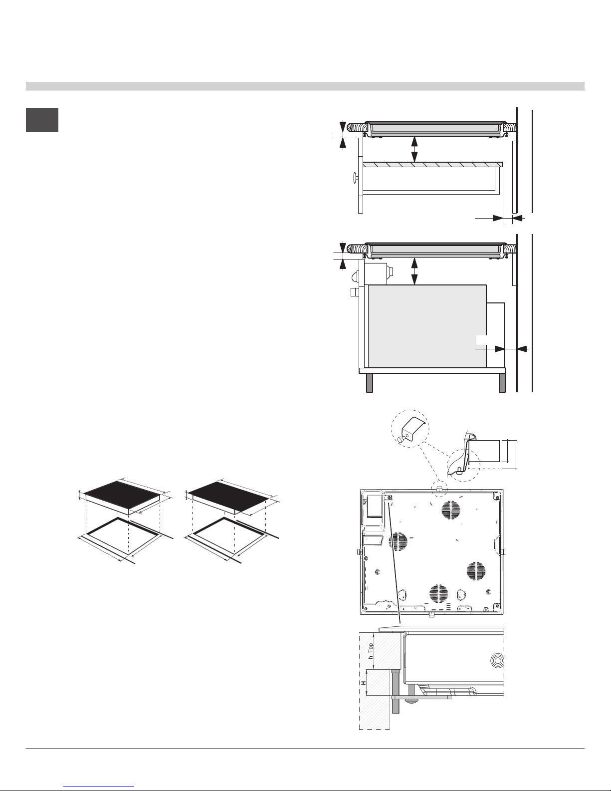
Built-in appliance
Use a suitable cabinet to ensure that the appliance
functions properly.
• The supporting surface must be heat-resistant up
to a temperature of approximately 100°C.
• If the appliance is to be installed above an oven,
the oven must be equipped with a forced
ventilation cooling system.
• Avoid installing the hob above a dishwasher: if
this cannot be avoided, place a waterproof
separation device between the two appliances.
• Depending on the hob you want to install, the
cabinet must have the following dimensions (
see
figure
):
560 +/- 1
490 +/- 1
48
590
520
690
520
560 +/- 1
490 +/- 1
48
FRONT SIDE
OF HOB
SUPPORTING
SURFACE
30
40
UNDERSIDE
OF HOB
5 mm
min. 20 mm
min. 20 mm
min. 40 mm
COMPARTMENT
5 mm
min. 40 mm
FAN-ASSISTED
OVE N
3
GB
Ventilation
To allow adequate ventilation and to avoid overheating
of the surrounding surfaces the hob should be positioned
as follows:
• At a minimum distance of 40 mm from the back
panel or any other vertical surfaces.
• So that a minimum distance of 20 mm is
maintained between the installation cavity and the
cabinet underneath.
Fixing
The appliance must be installed on a perfectly level
supporting surface.
Any deformities caused by improper fixing could
affect the features and operation of the hob.
The thickness of the supporting surface
should be
taken into account when choosing
the length of the
screws for the fixing hooks:
• 30 mm thick: 17,5 mm screws
• 40 mm thick: 7,5 mm screws
Fix the hob as follows:
1. Use short flat-bottomed screws to fix the 4
alignment springs in the holes provided at the
central point of each side of the hob.
2. Place the hob in the cavity, make sure it is in a
central position and push down on the whole
perimeter until the hob is stuck to the supporting
surface.
3. For hobs with raised sides: After inserting the hob
into its cavity, insert the 4 fixing hooks (each has its
own pin) into the lower edges of the hob, using the
long pointed screws to fix them in place, until the
glass is stuck to the supporting surface.
! The screws for the alignment springs must remain
accessible.
! In order to adhere to safety standards, the
appliance must not come into contact with electrical
parts once it has been installed.
! All parts which ensure the safe operation of the
appliance must not be removable without the aid of
a tool.
Electrical connection
! The electrical connection for the hob and for any
built-in oven must be carried out separately, both for
safety purposes and to make extracting the oven
easier.
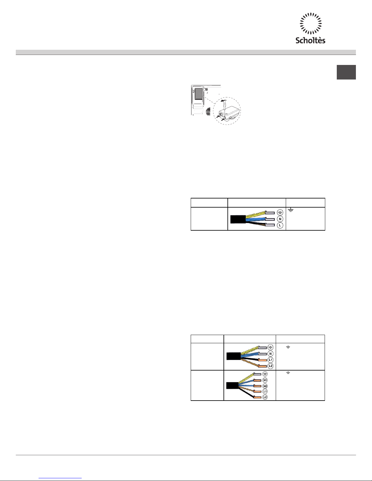
Terminal board
On the lower part of the
appliance there is a
connection box for the
different types of electricity
supply (the picture is only an
indication and is not an exact
representation of the
purchased model).
Single-phase connection
The hob is equipped with a pre-connected electricity
supply cable, which is designed for single-phase
connection. Connect the wires in accordance with
the instructions given in the following table and
diagrams:
V
ol tage an d
mains frequency
Electri cal cable Wire connection
230-240V 1+N ~
220-240V 1+N ~
50/ 60 Hz
: yellow/green;
N: the two blue wires
together
L: brown and black
together
Other types of connection
If the mains supply corresponds with one of the
following:
Voltage and mains frequency
• 400V - 2+N ~ 50/60 Hz
• 220-240V 3 ~ 50/60 Hz
• 230-240V 3 ~ 50/60 Hz
• 400V - 2+2N ~ 50/60 Hz
Separate the wires and connect them in accordance
with the instructions given in the following table and
diagrams:
V
olt age an d
mains frequency
Electrical cable Wire connection
400V - 2+N ~
50/60 Hz
230-24 0V 3 ~
220-24 0V 3 ~
50/60Hz
: yellow/green;
N: the two bl ue wires together
L1: black
L2: brown
400V - 2+2N ~
50/60 Hz
: yellow/green;
N1: bl ue
N2: bl ue
L1: black
L2: brown
UNDERSIDE OF HOB
4
GB
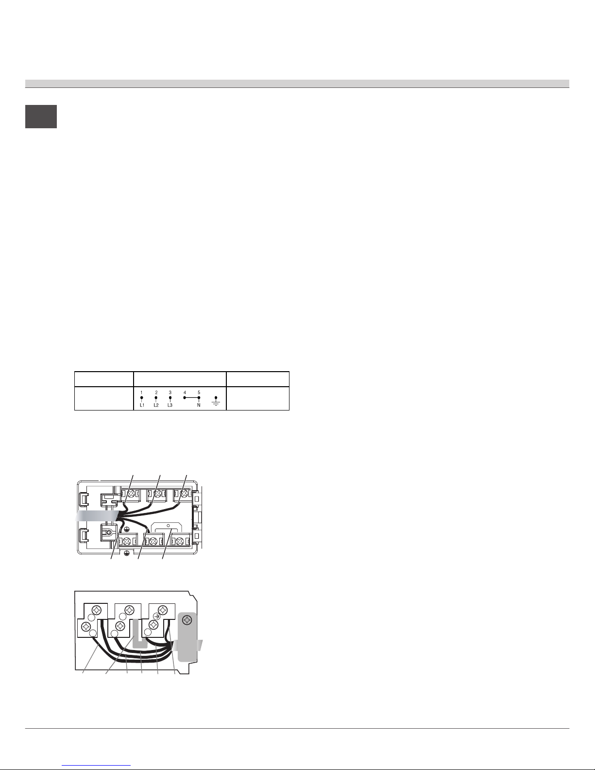
If the mains supply corresponds with one of the
following:
Voltage and mains frequency
• 400V 3 - N ~ 50/60 Hz
proceed as follows:
! The cable provided is not suitable for the following
types of installation.
1. Use a suitable supply cable, H05RR-F or higher,
with the right dimensions (cable cross section: 25
mm).
2. To open the terminal board, use a screwdriver as
a lever under the side tabs of the cover (
see
Terminal board picture
).
3. Loosen the cable clamp screw and the terminal
board screws in accordance with the type of
connection required and position the connection
supports as shown in the following table and
diagrams.
4. Position the wires in accordance with the
information given in the following table and diagrams
and connect the appliance by tightening all the
screws for the springs as much as possible.
V
ol tage a nd
mains frequenc
y
Electrical connections Terminal board
400V 3-N ~
50/60 Hz
Three-phase 400
5. Secure the power supply cable by fastening the
cable clamp screw, then put the cover back on.
U-bolt
connection support
Neutral
Earth
Phase Phase Phase
1
2
3
5
4
Three-phase 400
5
Fase Cavallotto Neutro TerraFase
1
2
3
4
Fase
Three-phase 400
Connecting the electricity supply cable to the
mains
If the appliance is being connected directly to the
electricity mains an omnipolar switch must be
installed with a minimum opening of 3 mm between
contacts.
! The installer must ensure that the correct electrical
connection has been made and that it is fully
compliant with safety regulations.
Before connecting the appliance to the power
supply, make sure that:
• The appliance is earthed and the plug is
compliant with the law.
• The socket can withstand the maximum power of
the appliance, which is indicated on the data
plate located on the appliance itself.
• The voltage falls within the range of values
indicated on the data plate.
• The socket is compatible with the plug of the
appliance. If the socket is incompatible with the
plug, ask an authorised technician to replace it.
Do not use extension cords or multiple sockets.
! Once the appliance has been installed, the power
supply cable and the electrical socket must be
easily accessible.
! The cable must not be bent or compressed.
! The cable must be checked regularly and replaced
by authorised technicians only.
! The manufacturer declines any liability should
these safety measures not be observed.
! Do not remove or replace the power supply cable
for any reason. Its removal or replacement will void
the warranty and the CE marking. INDESIT does not
assume liability for accidents or damage arising
from replacement/removal of the original power
supply cable. Replacement can only be accepted
when carried out by personnel authorised by
INDESIT and using an original spare part.
5
GB
Description of the
appliance
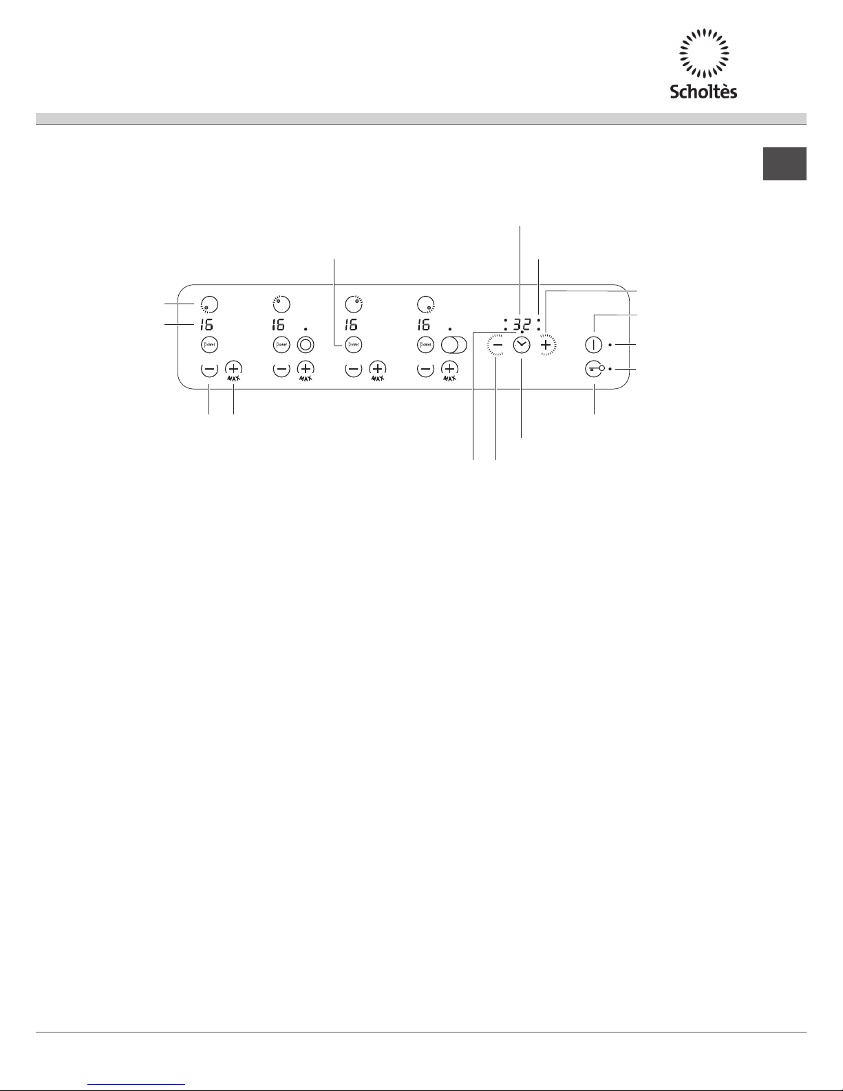
Control panel
• INCREASE POWER button switches on the
hotplate and controls the power (
see Start-up and
use
).
• REDUCE POWER button controls the power and
switches off the hotplate (
see Start-up and use
).
• COOKING ZONE indicator represents the
corresponding cooking zone.
• POWER indicator provides a visual display for the
current heat level.
• ON/OFF button switches the appliance on and off.
• ON/OFF indicator light shows whether the
appliance is on or off.
• PROGRAMME TIMER* button controls the
cooking programme times (
see Start-up and use
).
• PROGRAMME TIMER* display shows which
programme has been selected (
see Start-up and
use
).
• COOKING ZONE PROGRAMMED* indicator lights
show which cooking zones are being used during
a cooking programme (
see Start-up and use
).
• CONTROL PANEL LOCK button prevents
accidental changes to the hob settings (
see Start-
up and use
).
• CONTROL PANEL LOCK indicator light shows
the control panel has been locked (
see Start-up
and use
).
• TIMER* indicator light shows that the timer has
been activated
• INCREASE TIME* button increases the cooking
duration while the timer is running or while a set
programme is underway
(see Start-up and use).
• DECREASE TIME* button decreases the cooking
duration while the timer is running or while a set
programme is underway
(see Start-up and use).
! This product complies with the requirements of the
latest European Directive on the limitation of power
consumption of the standby mode.
If no operations are carried out for a period of 2
minutes, after the residual heat indicator lights turn
off and the fan stops (if present), the appliance
automatically switches to the “off mode”.
The appliance resumes the operating mode once the
ON/OFF button is pressed.
The control panel described in this manual is only a representative example: it may not exactly match the panel
on your appliance.
*
Only available in certain models.
ON/OFF indicator light
CONTROLS LOCKED
indicator light
CONTROL PANEL LOCK
button
INCREASE TIME*
button
COOKING ZONE PROGRAMMED*
indicator light
PROGRAMME TIMER*
display
PROGRAMME TIMER
button
DECREASE TIME*
button
POWER and
RESIDUAL HEAT
indicators
ON/OFF button
COOKING ZONE
indicator
TIMER*
indicator light
POWER*
button
INCREASE POWER
button
DECREASE POWER
button
p
o w erpo w er
p
o w erpo w er
p
o w erpo w er
p
o w erpo w er
 Loading...