

Page 1
Istruzioni per luso
PIANO COTTURA
IT
Italiano, 1
41
TEM 748 L
GB FR
English,14
Français, 27
DENL
Deutsch, 55Nederlands,
Sommario
IT
Installazione, 2-7
Posizionamento
Collegamento gas
Caratteristiche dei bruciatori ed ugelli
Collegamento elettrico
Descrizione dellapparecchio, 8
Pannello di controllo
Avvio e utilizzo, 9-10
Consigli pratici per luso dei bruciatori
Consigli pratici per luso dellapparecchio
Descrizione degli elementi riscaldanti
Descrizione tecnica delle zone di cottura
Precauzioni e consigli, 11
Sicurezza generale
Smaltimento
Manutenzione e cura, 12
Escludere la corrente elettrica
Pulire lapparecchio
Smontare il piano
Manutenzione rubinetti gas
Anomalie e rimedi, 13
Assistenza attiva 7 giorni su 7
Page 2
Installazione
È importante conservare questo libretto per poterlo
IT
consultare in ogni momento. In caso di vendita, di
cessione o di trasloco, assicurarsi che resti insieme
allapparecchio per informare il nuovo proprietario sul
funzionamento e sui relativi avvertimenti.
Leggere attentamente le istruzioni: ci sono importanti
informazioni sullinstallazione, sulluso e sulla sicurezza.
Posizionamento
Gli imballaggi non sono giocattoli per bambini e vanno
eliminati secondo le norme per la raccolta differenziata
(vedi Precauzioni e consigli).
Linstallazione va effettuata secondo queste istruzioni e
da personale professionalmente qualificato. Una errata
installazione può causare danni a persone, animali o
cose.
Questo apparecchio può essere installato e funzionare
solo in locali permanentemente ventilati secondo le
prescrizioni delle norme UNI-CIG 7129 e 7131 e
successivi aggiornamenti in vigore. Debbono essere
osservati i seguenti requisiti:
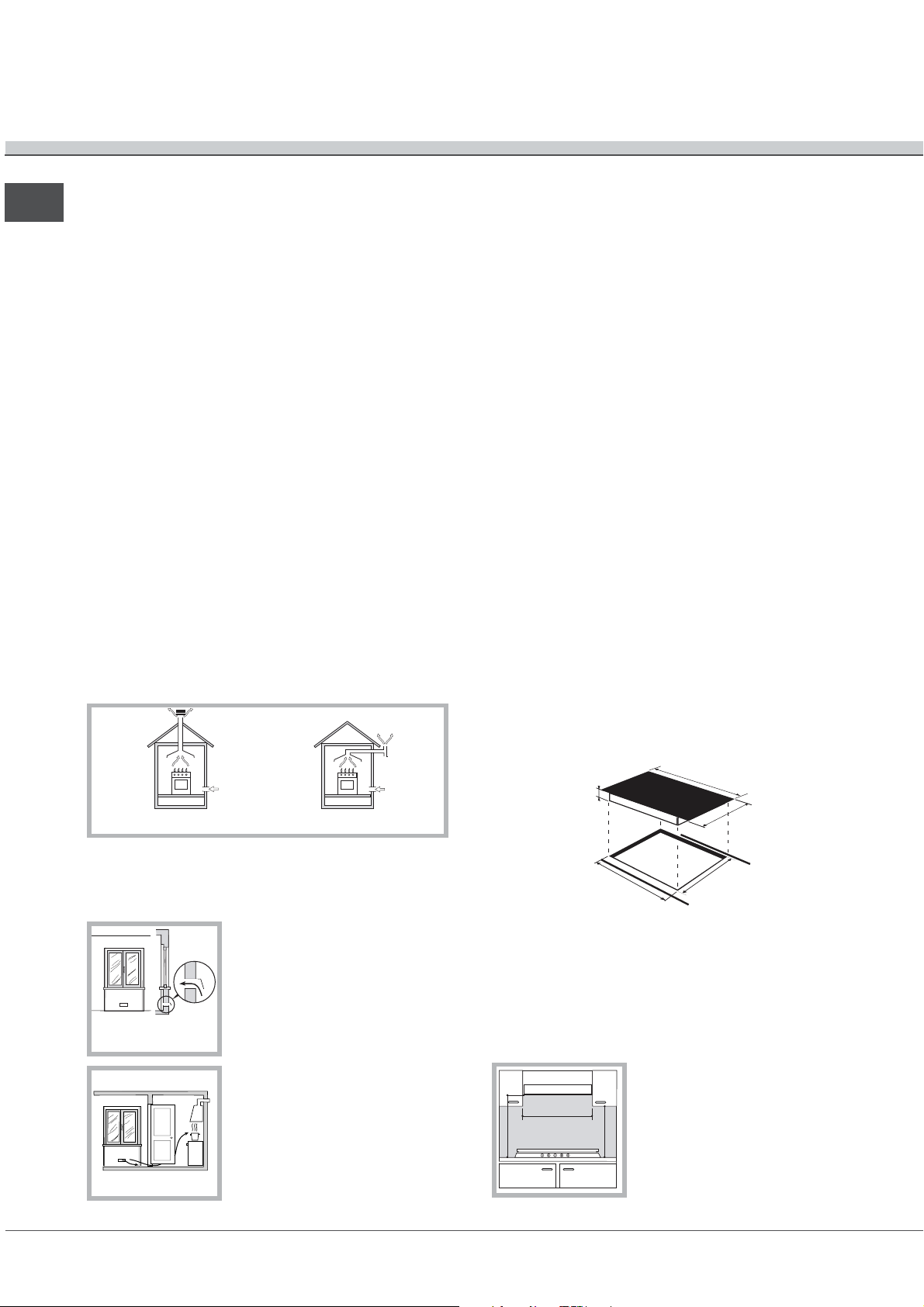
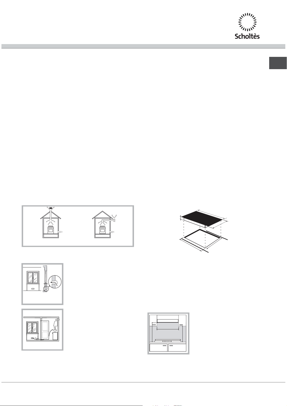
Il locale deve prevedere un sistema di scarico
allesterno dei fumi della combustione, realizzato
tramite una cappa o tramite un elettroventilatore che
entri automaticamente in funzione ogni volta che si
dellimmobile, o ambienti con pericolo di incendio, o
camere da letto.
I gas di petrolio liquefatti, più pesanti dellaria,
ristagnano verso il basso. Quindi i locali contenenti
bidoni di GPL debbono prevedere delle aperture verso
lesterno così da permettere levacuazione dal basso
delle eventuali fughe di gas. Pertanto i bidoni di GPL,
siano essi vuoti o parzialmente pieni, non debbono
essere installati o depositati in locali o vani a livello più
basso del suolo (cantinati, ecc.). É opportuno tenere
nel locale solo il bidone in utilizzo, collocato in modo da
non essere soggetto allazione diretta di sorgenti di
calore (forni, camini, stufe, ecc.) capaci di portarlo a
temperature superiori ai 50°C.
Incasso
Per garantire un buon funzionamento dellapparecchio è
necessario che il mobile abbia le caratteristiche adatte:
il piano dappoggio deve essere di materiale
resistente al calore, a una temperatura di circa
100°C;
se si desidera installare il piano cottura sopra un
forno, questo deve essere provvisto di un sistema
di raffreddamento a ventilazione forzata;
evitare di installare il piano cottura sopra una
lavastoviglie: alloccorrenza frapporre un elemento
di
separazione a tenuta stagna fra i due
apparecchi;
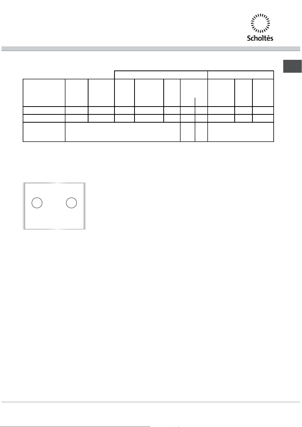
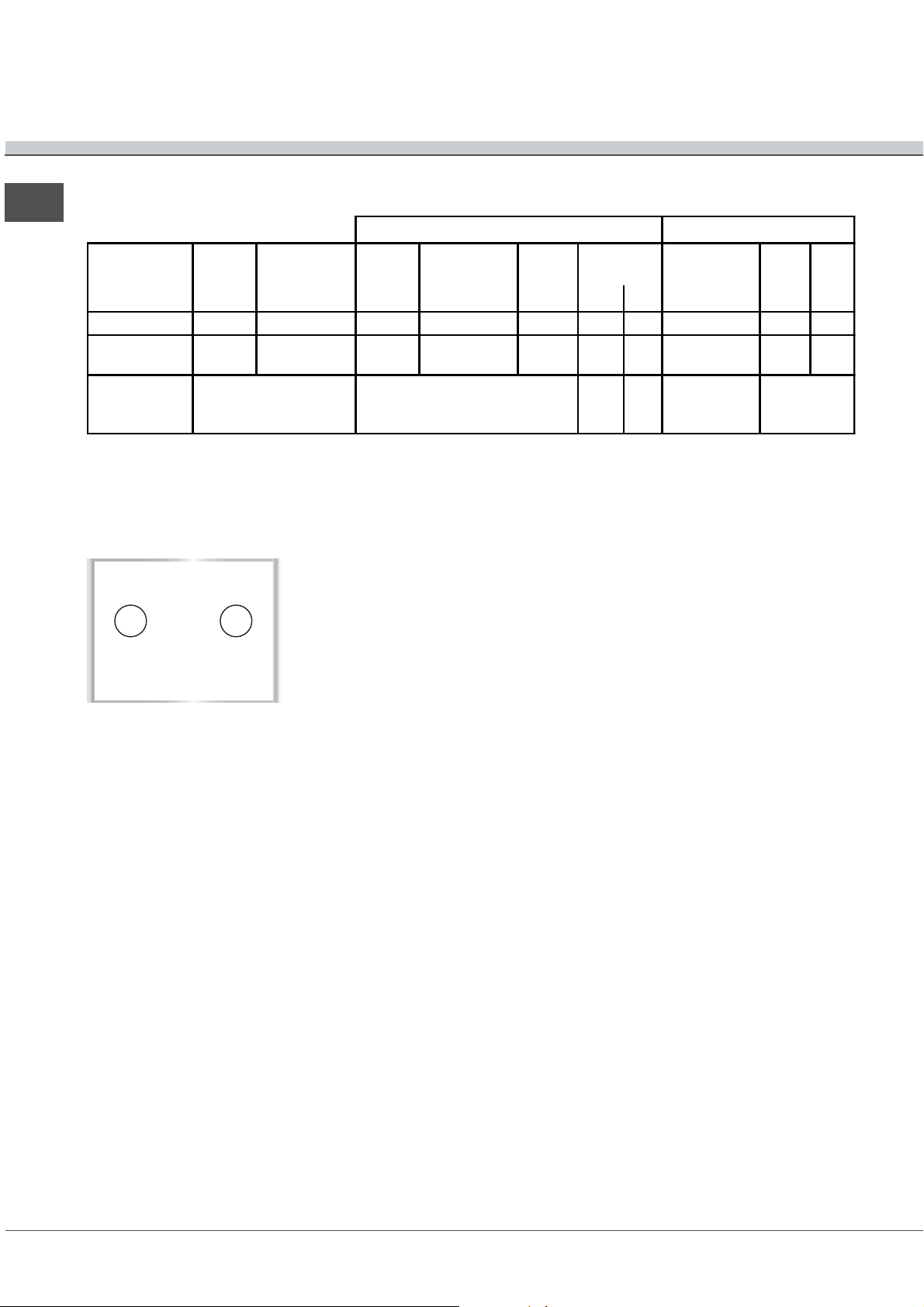
a seconda del piano cottura che si desidera
installare (vedi figure), il vano del mobile deve
avere le seguenti dimensioni:
In camino o in canna fumaria ramificata
(riservata agli apparecchi di cottura)
Direttamente
all’esterno
accende lapparecchio.
Il locale deve prevedere un sistema che consenta
lafflusso dellaria necessaria alla regolare combustione.
La portata di aria necessaria alla combustione non
deve essere inferiore a 2 m
kW di potenza installata.
Il sistema può essere realizzato
prelevando direttamente laria
A
Esempi di aperture di
ventilazione
per l’aria comburente
dallesterno delledificio tramite un
condotto di almeno 100 cm
sezione utile e tale che non
possa essere accidentalmente
Locale
adiacente
Locale
da ventilare
ostruito.
Ovvero, in maniera indiretta da
locali adiacenti, dotati di un
condotto di ventilazione con
Maggiorazione della fessura
fra porta e pavimento
lesterno come sopra descritto, e
che non siano parti comuni
3
/h per
2
di
690
48
560 +/- 1
520
490 +/- 1
I mobili situati a fianco, la cui altezza superi quella del
piano di lavoro, debbono essere situati ad almeno 600
mm dal bordo del piano stesso.
Le cappe debbono essere installate secondo i requisiti
richiesti nei libretti istruzioni delle cappe stesse,
comunque ad una distanza minima di 650 mm.
Posizionare i pensili adiacenti alla cappa ad unaltezza
minima dal top di 420 mm (vedi
figura).
600mm min.
700mm min.
Allorchè il piano di cottura venga
installato sotto un pensile,
questultimo dovrà mantenere
540mm min.
una distanza minima dal top pari
a 700 mm (vedi figura).
2
Page 3
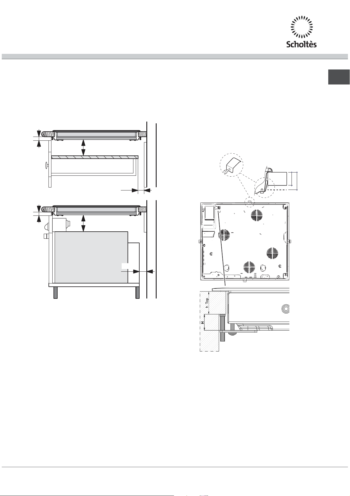
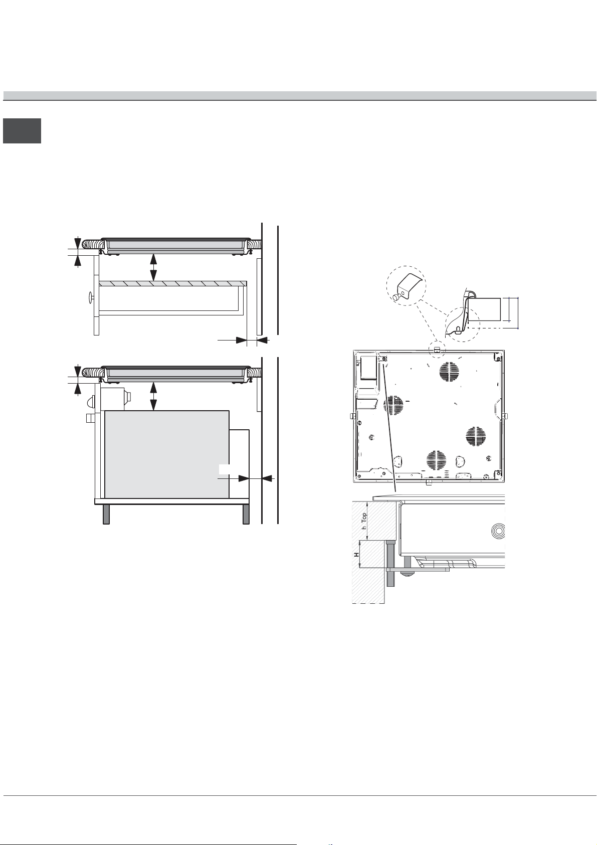
Aerazione
Per consentire unadeguata aerazione e per evitare
il surriscaldamento delle superfici attorno
allapparecchio, il piano cottura deve essere posizionato:
a una distanza minima di 40 mm dalla parete
retrostante;
in modo da mantenere una distanza minima di 20 mm
fra il vano per lincasso e il mobile sottostante.
min. 20 mm
5 mm
CASSETTO
min. 40 mm
min. 20 mm
5 mm
FORNO
VENTILATO
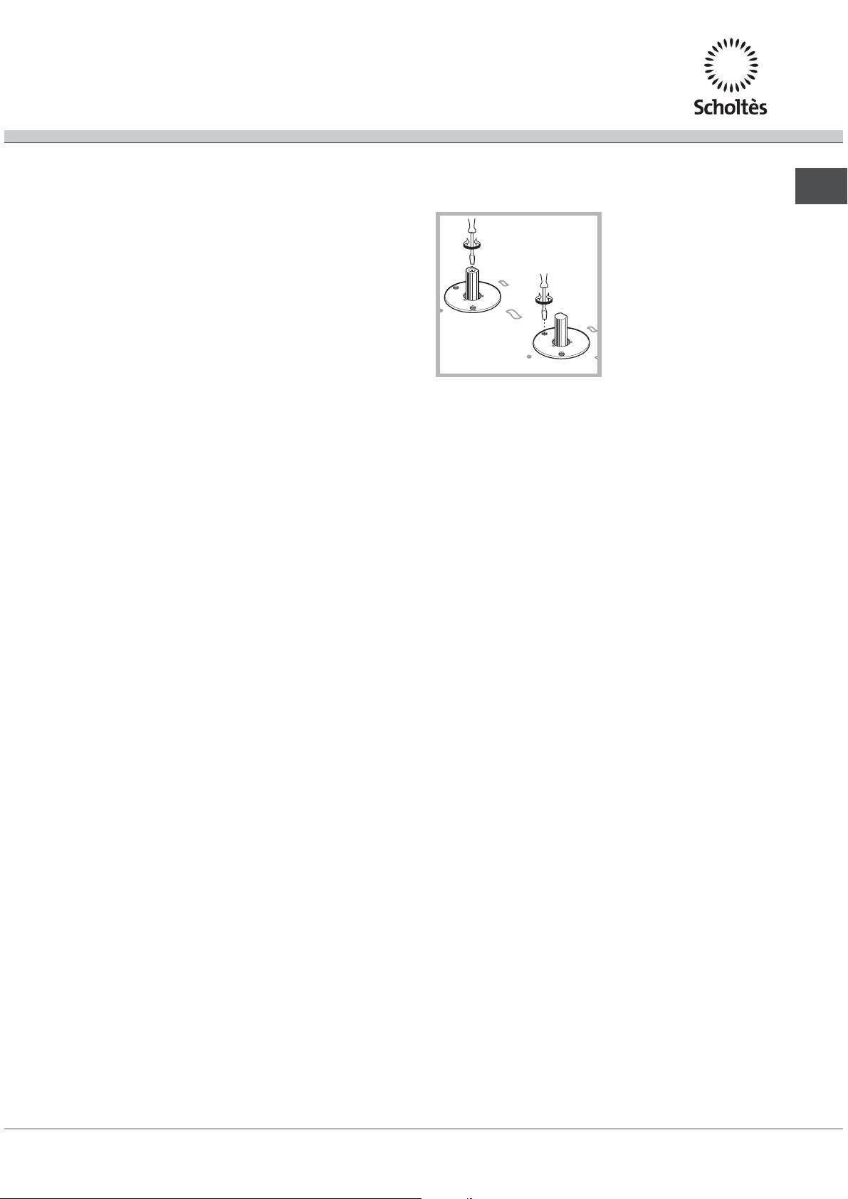
piano cottura, avvitandoli con le viti lunghe con punta
finché il vetro non aderisce al piano dappoggio.
È indispensabile che le viti delle molle di centraggio
rimangano accessibili.
In conformità alle norme di sicurezza, una volta
incassato lapparecchio, non debbono essere possibili
eventuali contatti con le parti
Tutte le parti che assicurano la protezione debbono
essere fissate in modo tale da non poter essere tolte
senza laiuto di qualche utensile.
PIANO COTTURA
ROVESCIATO
elettriche.
LATO ANTERIORE
DEL PIANO COTTURA
PIANO DI
APPOGGIO
30
40
IT
min. 40 mm
Fissaggio
Linstallazione dellapparecchio deve essere effettuata
su un piano dappoggio perfettamente piano.
Le eventuali deformazioni provocate da un errato
fissaggio potrebbero alterare le caratteristiche e
le prestazioni del piano cottura.
La lunghezza della vite di regolazione dei ganci
di fissaggio va impostata prima del loro montaggio,
in base allo
spessore di 30 mm: vite 17,5 mm;
spessore di 40 mm: vite 7,5 mm.
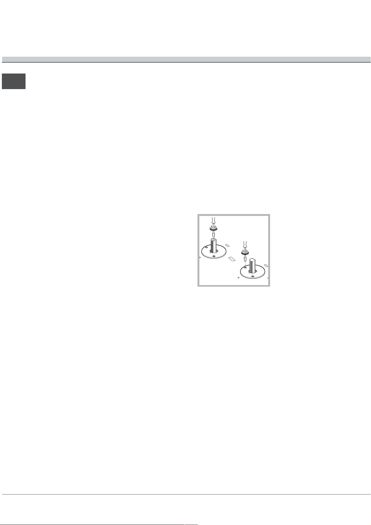
Per il fissaggio agire come segue:
1. Con le viti corte senza punta, avvitare le 4 molle di
centraggio nei fori posti al centro di ogni lato del piano;
2. inserire il piano cottura nel vano del mobile, centrarlo
ed esercitare una adeguata pressione sullintero
perimetro affinché il piano di cottura aderisca bene al
piano dappoggio.
3. per i piani con profili laterali: dopo aver inserito il
piano cottura nel mobile, inserire i 4 ganci di fissaggio
(ognuno con il suo perno) sul perimetro inferiore del
spessore del piano dappoggio:
Collegamento gas
Il collegamento dellapparecchio alla tubazione o alla
bombola del gas dovrà essere effettuato come
prescritto dalle norme UNI-CIG 7129 e 7131 e
successivi aggiornamenti, solo dopo essersi accertati
che esso è regolato per il tipo di gas con cui sarà
alimentato. In caso contrario eseguire le operazioni
indicate al paragrafo Adattamento ai diversi tipi di
gas.
Nel caso di alimentazione con gas liquido da
bombola, utilizzare regolatori di pressione conformi
alle norme UNI EN 12864 e successivi aggiornamenti in
vigore.
3
Page 4
Per un sicuro funzionamento, per un adeguato uso
IT
dellenergia e maggiore durata dellapparecchiatura,
assicurarsi che la pressione di alimentazione rispetti
i valori indicati nella tabella 1 Caratteristiche dei
bruciatori ed ugelli.
Allaccio con tubo rigido (rame o acciaio)
Lallaccio allimpianto gas deve essere effettuato in
modo da non provocare sollecitazioni di alcun
genere allapparecchio.
Sulla rampa di alimentazione dellapparecchio è
presente un raccordo a L orientabile, la cui tenuta
è assicurata da una guarnizione. Nel caso risulti
necessario ruotare il raccordo sostituire
tassativamente la guarnizione di tenuta (in dotazione
con lapparecchio). Il raccordo di entrata del gas
allapparecchio è filettato 1/2 gas maschio cilindrico.
Allaccio con tubo flessibile in acciaio
inossidabile a parete continua con attacchi
filettati
Il raccordo di entrata del gas allapparecchio è
filettato 1/2 gas maschio cilindrico.
La messa in opera di tali tubi deve essere e
in modo che la loro lunghezza, in condizioni di
massima estensione, non sia maggiore di 2000 mm.
Ad allacciamento avvenuto assicurarsi che il tubo
metallico flessibile non venga a contatto con parti
mobili o schiacciato.
Verificare che il tubo sia conforme alle norme UNI-
CIG 9891 e le guarnizioni di tenuta metalliche in
alluminio conformi alla UNI 9001-2 o guarnizioni in
gomma conformi alla UNI EN 549.
Controllo Tenuta
Ad installazione ultimata controllare la perfetta
tenuta di tutti i raccordi utilizzando una soluzione
saponosa e mai una fiamma.
Adattamento ai diversi tipi di gas
Per adattare il piano ad un tipo di gas diverso da
quello per il quale esso è predisposto (indicato sulla
etichetta fissata nella parte inferiore del piano o
sull'imballo), occorre sostituire gli ugelli dei
bruciatori effettuando le seguenti operazioni:
1. togliere le griglie del piano e sfilare i bruciatori
dalle loro sedi.
ffettuata
2. svitare gli ugelli, servendosi di una chiave a tubo
da 7mm. e sostituirli con quelli adatti al nuovo
tipo di gas (
bruciatori ed ugelli).
3. rimontare le parti eseguendo allinverso le
operazioni.
4. al termine delloperazione, sostituite la vecchia
etichetta taratura con quella corrispondente al
nuovo gas dutilizzo, reperibile presso i Nostri
Centri Assistenza Tecnica.
Regolazione aria primaria dei bruciatori
I bruciatori non necessitano di nessuna regolazione
dellaria primaria.
Regolazione minimi
1. Portare il rubinetto sulla posizione di minimo;
3. Verificare che ruotando rapidamente la manopola
dalla posizione di massimo a quella di minimo
non si abbiano spegnimenti dei bruciatori.
4. Negli apparecchi provvisti del dispositivo di
sicurezza (termocoppia), in caso di mancato
funzionamento del dispositivo con bruciatori al
minimo aumentare la portata dei minimi stessi
agendo sulla vite di regolazione.
5. Effettuata la regolazione, ripristinate i sigilli posti
sui by-pass con ceralacca o materiali equivalenti.
Nel caso dei gas liquidi, la vite di regolazione
dovrà essere avvitata a fondo.
Al termine delloperazione sostituire la vecchia
etichetta di taratura con quella corrispondente al
nuovo gas di utilizzo, reperibile presso i nostri Centri
Assistenza Tecnica.
Qualora la pressione del gas utilizzato sia diversa
(o variabile) da quella prevista,
installare, sulla tubazione dingresso un appropriato
regolatore di pressione (secondo norme EN 88-1 e
EN88-2 regolatori per gas canalizzati).
vedi tabella 1 Caratteristiche dei
2.Togliere la manopola
ed agire sulla vite di
regolazione posta
allinterno o di fianco
allastina del rubinetto
fino ad ottenere una
piccola fiamma
regolare.
è necessario
4
Page 5
Caratteristiche dei bruciatori ed ugelli
Tabella 1 Gas liquido Gas naturale
Bruciatore Diametro
(mm)
Semi Rapido (S) 75 0,40 28 1,80 67 131 129 1,80 102 171
Tripla Corona (TC) 130 1,30 57 3,30 87 240 236 3,60 131 343
Pressioni
di
alimentazione
* A 15°C e 1013 mbar-gas secco
** Propano P.C.S. = 50.37 MJ/Kg
*** Butano P.C.S. = 49.47 MJ/Kg
Naturale P.C.S. = 37.78 MJ/m
TC S
Potenza
termica
kW (p.c.s.*)
By-Pass
1/100
Potenza
termica
kW (p.c.s.*)
ugello
1/100
portata*
g/h
Potenza
termica
kW (p.c.s.*)
Ridot. (mm) Nomin. (mm) *** ** Nomin. (mm)
Nominale (mbar)
Minima (mbar)
Massima (mbar)
3
28-30
20
35
37
25
45
ugello
1/100
20
17
25
portata*
IT
l/h
TEM 748 L
5
Page 6
Collegamento elettrico
IT
Lallacciamento elettrico del piano cottura e quello di
un eventuale forno da incasso devono essere realizzati
separatamente, sia per ragioni di sicurezza elettrica sia
per facilitare le operazioni di estrazione del forno.
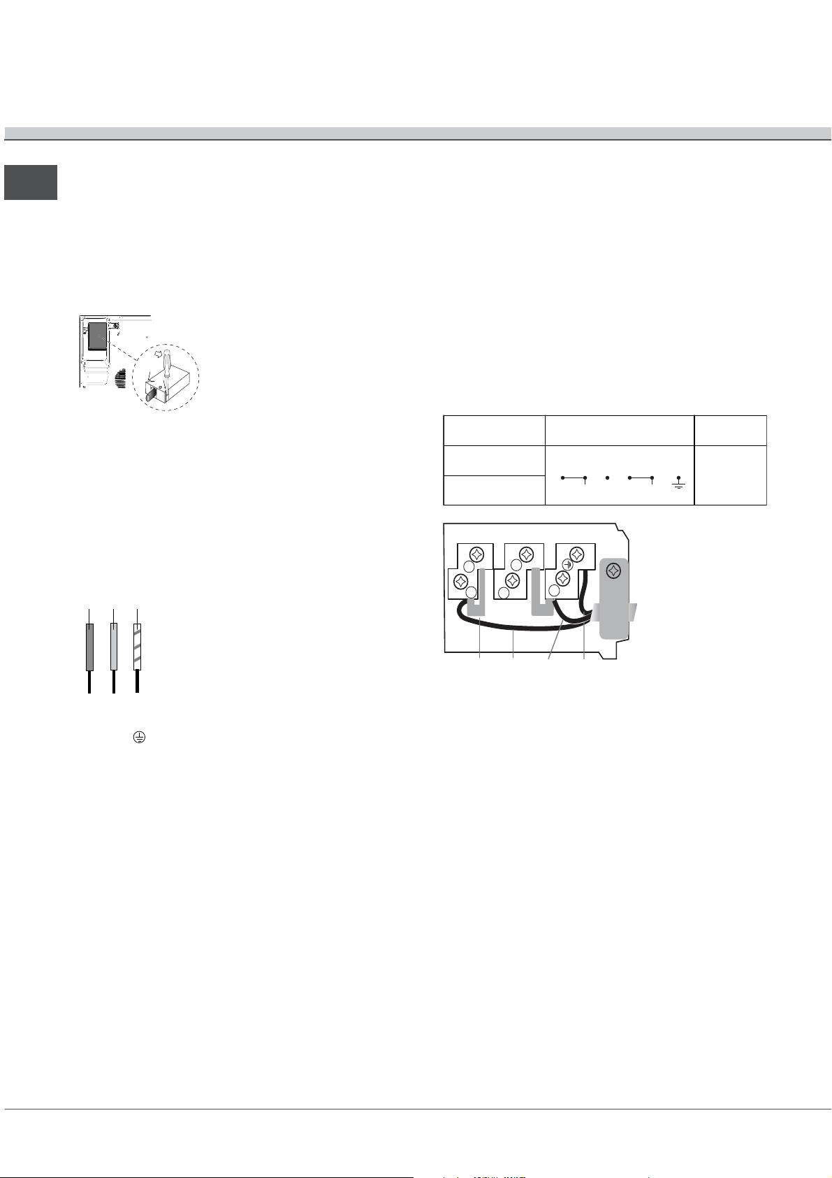
Morsettiera
PIANO COTTURA
ROVESCIATO
Lapparecchio è provvisto, nella
parte inferiore, di una scatola
per il collegamento a differenti
tipi di alimentazione elettrica
(limmagine è indicativa e può
non corrispondere al modello
acquistato).
Se il piano non è dotato di cavo alimentazione collegato,
procedere come segue:
1. Utilizzare il cavo di alimentazione in dotazione (ove
presente) o un cavo di alimentazione appropriato, tipo
H05VV-F o di valore superiore, delle dimensioni adatte
(sezione cavo: 2,5 mm).
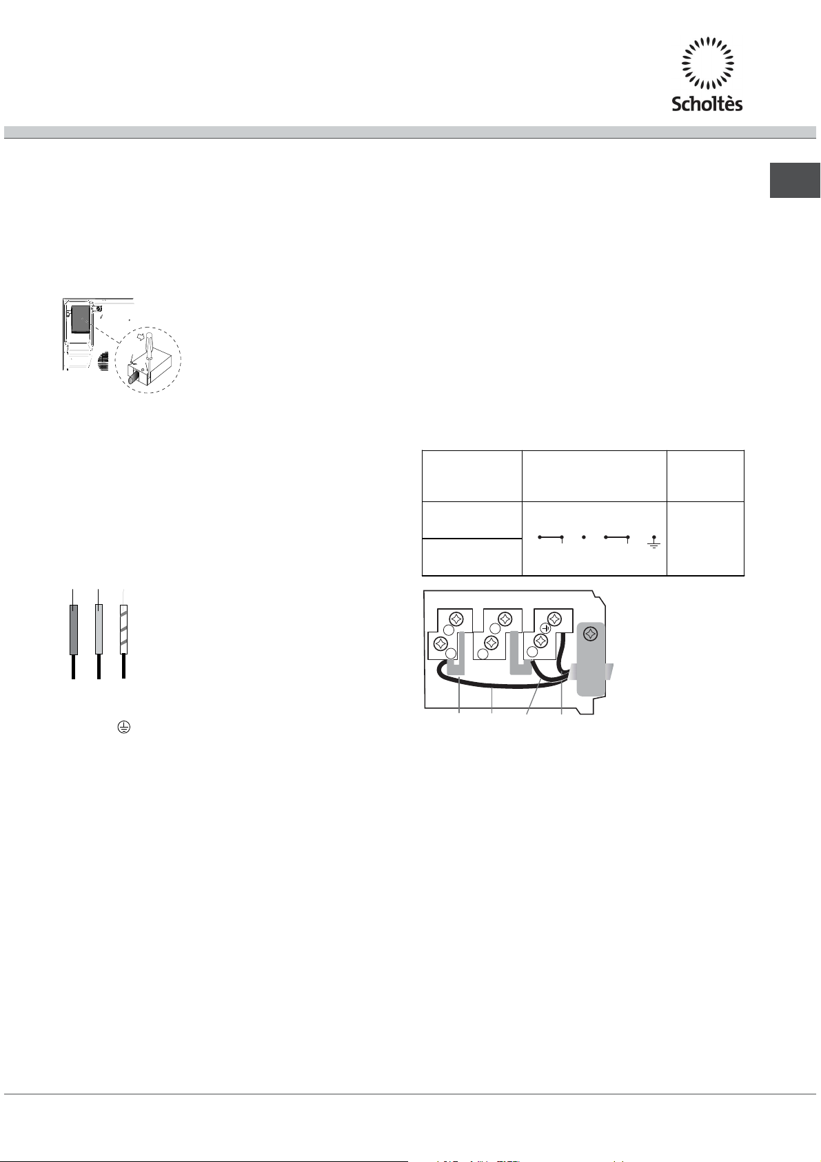
2. Servendosi di un cacciavite, far leva sulle linguette
del coperchio della morsettiera e aprirla (vedi immagine
Morsettiera).
3. La morsettiera è già predisposta per il collegamento
monofase: accertarsi che i cavallotti di collegamento tra
i morsetti 1 e 2 e quelli tra 4 e 5 siano in posizione
corretta (vedi immagine Monofase).
4. Posizionare i fili in accordo con il disegno e la tabella
che seguono ed effettuare il collegamento stringendo a
fondo tutte le viti dei morsetti.
Collegamento monofase
Leventuale cavo in dotazione è predisposto
unicamente per questo tipo di installazioni.
Caratteristiche dellimpianto elettrico:
Tensione tipo e frequenza di rete
220-240V 1+N ~ 50 Hz
220-240V 2 ~ 50 Hz
Blu
Marrone
Verde / Giallo
Se il piano è dotato di cavo
di alimentazione già collegato,
allacciarlo alla rete rispettando
il colore dei fili come da schema
a fianco.
Terre
Phase
Neutre
L
N
Tensione tipo e
frequenza rete
220-240V 1+N ~
50 Hz
220-240V 2 ~ 50
Hz
Collegamenti elettrici Morsettiera
12345
LN
Monofase
2
1
4
3
FaseCavallotto Neutro Terra
5
5. Fissare il cavo di alimentazione nellapposito
fermacavo e chiudere il coperchio.
Monofase
6
Page 7
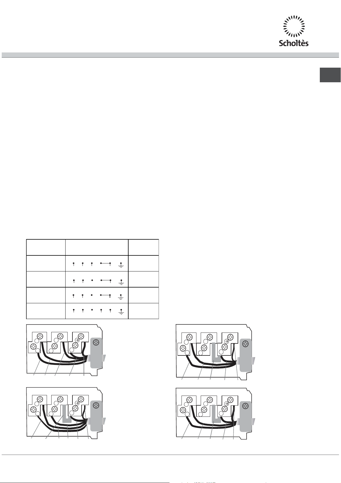
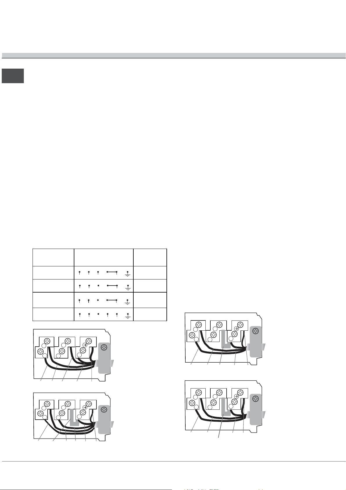
Altri tipi di collegamento
Leventuale cavo in dotazione non è utilizzabile per
questi tipi di installazione.
Se limpianto elettrico corrisponde a una delle seguenti
caratteristiche:
Tensione tipo e frequenza di rete
400V 3 - N ~ 50 Hz
400V 2 - N ~ 50 Hz
220-240V 3 ~ 50 Hz
220-240V 2 + 2 - N
~ 50 Hz
5. Fissare
il cavo di alimentazione nellapposito
fermacavo e chiudere il coperchio.
Allacciamento del cavo di alimentazione alla
rete
In caso di collegamento diretto alla rete è necessario
interporre tra lapparecchio e la rete un interruttore
onnipolare con apertura minima fra i contatti di 3 mm.
Linstallatore è responsabile del corretto collegamento
elettrico e dellosservanza delle norme di sicurezza.
IT
procedere come segue:
1. Utilizzare un cavo di alimentazione appropriato, tipo
H05RR-F o di valore superiore, delle dimensioni adatte
(sezione cavo: 1,5 mm).
2. Servendosi di un cacciavite, far leva sulle linguette
del coperchio della morsettiera e aprirla (vedi immagine
Morsettiera).
3. Svitare la vite del serracavo e le viti dei
morsetti
relativi al tipo di allaccio necessario e posizionare i
cavallotti di collegamento secondo la tabella e i disegni
che seguono.
4. Posizionare i fili in accordo con la tabella e i disegni
che seguono ed effettuare il collegamento stringendo a
fondo tutte le viti dei morsetti.
Tensione tipo e
frequenza rete
400V 3-N ~
50 Hz
400V 2-N ~
50 Hz
220-240V 3 ~ 50
Hz
220-240V 2+2-
N~ 50 Hz
Collegamenti elettrici Morsettiera
12345
L1 L2 L3 N
12345
L1 L2 N
12345
L1 L2 L3
12 34
L1
L2
5
N2N1
Trifase 400
Trifase 400
2+N
Trifase 230
Bifase
Prima di effettuare lallacciamento accertarsi che:
la presa abbia la messa a
terra e sia a norma di
legge;
la presa sia in grado di sopportare il carico massimo
di potenza della macchina, indicato nella
targhetta caratteristiche posta sullapparecchio;
la tensione di alimentazione sia compresa nei valori
della targhetta caratteristiche;
la presa sia compatibile con la spina
dellapparecchio. In caso contrario sostituire la presa
o
la spina; non usare prolunghe e multiple.
Ad apparecchio installato, il cavo elettrico e la presa
della corrente devono essere facilmente raggiungibili.
Il cavo non deve subire piegature o compressioni.
Il cavo deve essere controllato periodicamente e
sostituito solo da tecnici autorizzati.
Lazienda decli
na ogni responsabilità qualora queste
norme non vengano rispettate.
2
1
Fase Neutro TerraFase Neutro
2
1
Fase Cavallotto Neutro TerraFase
4
3
4
3
Fase
Bifase
Trifase 400 2+N
Fase
4
3
5
2
5
1
Fase NeutroCavallotto Terra
Trifase 400
Trifase 230
Fase
4
3
5
2
5
1
Fase FaseCavallotto Terra
7
Page 8
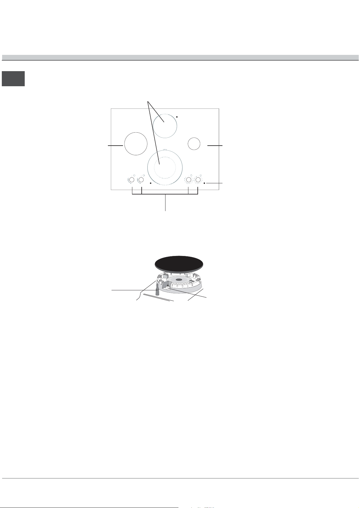
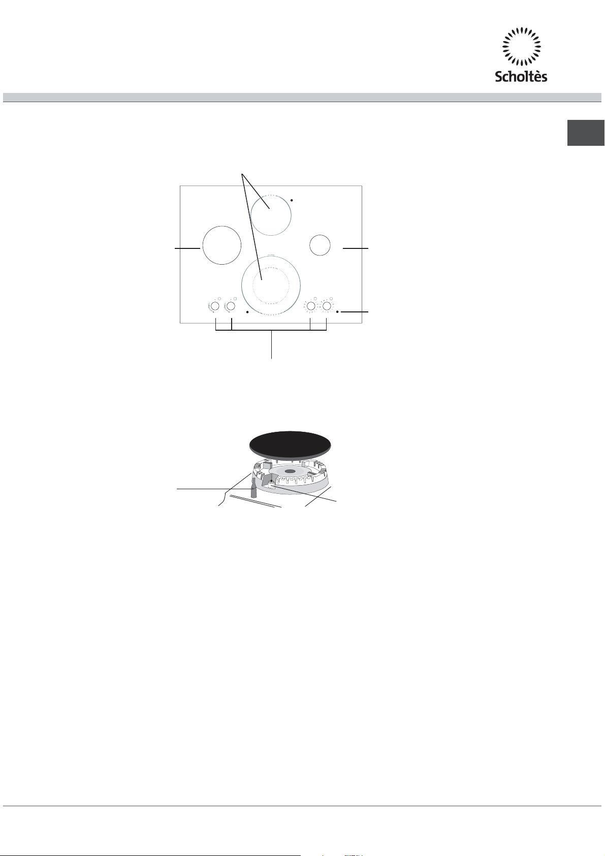
Descrizione
dellapparecchio
Pannello di controllo
IT
BRUCIATORE
GAS
VETROCERAMICA
PIASTRA
O
G
L
E
A
N
H
DD
OO
WW
00
UU
00
BB
55
LL
22
EE
RR
GG
II
NN
Manopole di comando dei
BRUCIATORI GAS e delle
PIASTRE VETROCERAMICA
BRUCIATORE
GAS
Spia funzionamento
PIASTRA VETROCERAMICA
DISPOSITIVO DI
SICUREZZA
Spia FUNZIONAMENTO PIASTRA
VETROCERAMICA si accende per qualsiasi
posizione della manopola diversa da quella di
spento
BRUCIATORI GAS sono di diverse dimensioni e
potenze. Scegliete quello più adatto al diametro
del recipiente da utilizzare.
Manopole di comando dei BRUCIATORI GAS e
della PIASTRA VETROCERAMICA per la
regolazione della fiamma o della potenza.
Candela di accensione dei
BRUCIATORI GAS
Candela di accensione dei BRUCIATORI GAS
permette laccensione automatica del bruciatore
prescelto.
DISPOSITIVO DI S
ICUREZZA in caso di
spegnimento accidentale della fiamma,
interrompe luscita del gas.
8
Page 9
Avvio e utilizzo
La colla applicata sulle guarnizioni lascia alcune
tracce di grasso sul vetro. Prima di utilizzare
lapparecchio, si raccomanda di eliminarle con un
prodotto specifico per la manutenzione non abrasivo.
Durante le prime ore di funzionamento è possibile
avvertire un odore di gomma, che comunque
scomparirà presto.
Su ciascuna manopola è indicata la posizione del
bruciatore gas o della piastra vetroceramica
corrispondente.
Bruciatori gas
Il bruciatore prescelto può essere regolato dalla
manopola corrispondente come segue:
Spento
Massimo
Minimo
Per accendere uno dei bruciatori, avvicinare allo
stesso una fiamma o un accenditore, premere a
fondo e ruotare la manopola corrispondente in senso
antiorario fino alla posizione di massima potenza.
Nei modelli dotati di dispositivo di sicurezza, è
necessario mantenere premuta la manopola per
circa 2-3 secondi finchè non si scalda il dispositivo
che mantiene automaticamente accesa la fiamma.
Nei modelli dotati di candela di accensione, per
accendere il bruciatore prescelto, premere a fondo e
ruotare la manopola corrispondente in senso
antiorario fino alla posizione di massima potenza,
tenendola premuta fino allavvenuta accensione.
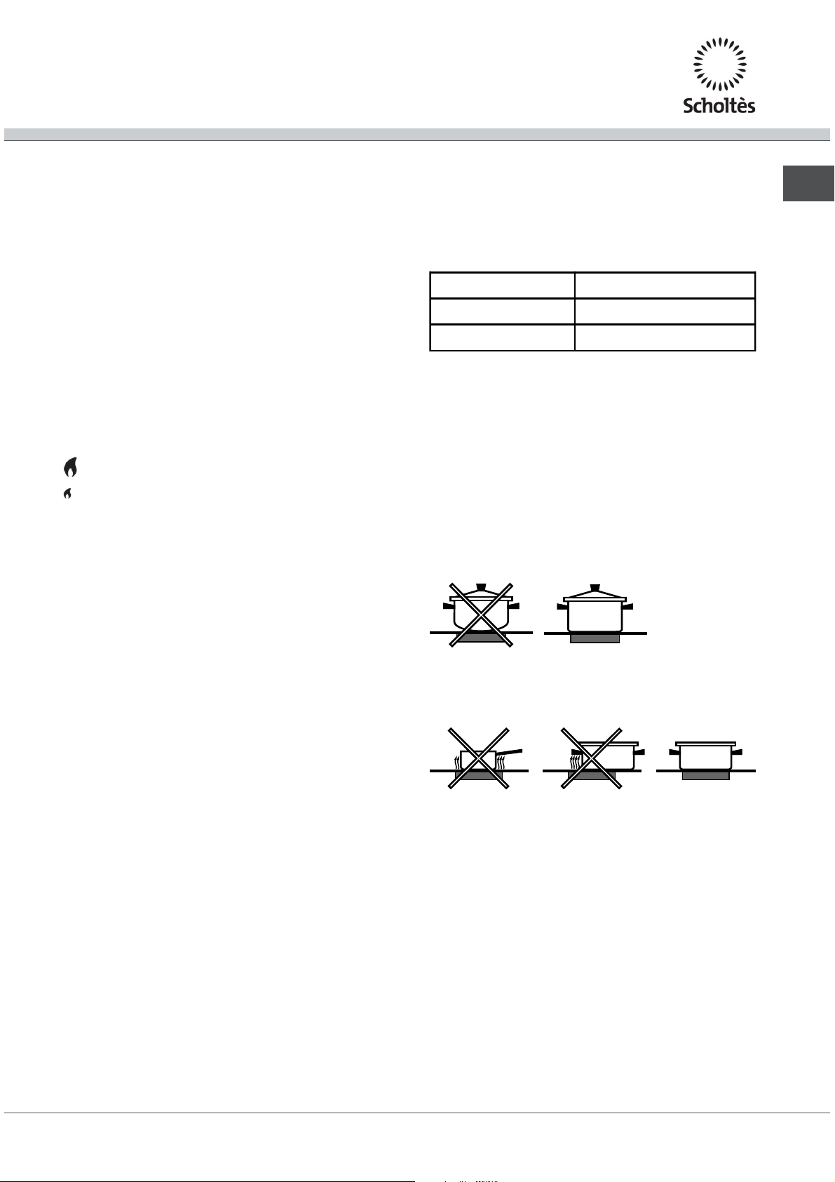
utilizzare sempre recipienti a fondo piatto e con
coperchio.
al momento dellebollizione ruotare la manopola
fino alla posizione di minimo.
Bruciatore ø Diametro recipienti (cm)
Semi Rapido (S) 16 – 20
Tripla Corona (TC) 24 – 26
Per identificare il tipo di bruciatore fate riferimento ai
disegni presenti nel paragrafo "Caratteristiche dei
bruciatori ed ugelli".
Consigli pratici per luso
dellapparecchio
Per ottenere le migliori prestazioni dal piano di
cottura:
adoperare pentole con fondo piatto per essere
certi che aderiscano perfettamente alla zona
riscaldante;
adoperare sempre pentole di diametro sufficiente
a coprire completamente la zona riscaldante, in
modo da garantire lo sfruttamento di tutto il calore
disponibile;
IT
Nel caso di una estinzione accidentale delle
fiamme del bruciatore, chiudere la manopola di
comando e ritentare laccensione dopo almeno 1
minuto.
Per spegnere il bruciatore occorre ruotare la
manopola in senso orario fino allarresto
(corrispondente al simbolo ).
Consigli pratici per luso dei bruciatori
Al fine di ottenere il massimo rendimento è utile
ricordare quanto segue:
utilizzare recipienti adeguati a ciascun bruciatore
(vedere tabella) al fine di evitare che le fiamme
fuoriescano dal fondo dei recipienti.
accertarsi che il fondo delle pentole sia sempre
perfettamente asciutto e pulito, per garantire la
corretta aderenza e una lunga durata, sia alle
zone di cottura che alle pentole stesse;
evitare di utilizzare le stesse pentole utilizzate
sui bruciatori a gas: la concentrazione di calore
sui bruciatori a gas può deformare il fondo della
pentola, che perde aderenza;
non lasciare mai una zona di cottura accesa
senza pentola poiché il suo riscaldamento,
raggiungendo rapidamente il livello massimo,
potrebbe danneggiare gli elementi riscaldanti.
9
Page 10
Descrizione degli elementi riscaldanti
IT
Gli elementi radianti sono composti da resistenze
circolari. Diventano rossi solo dopo alcune decine di
secondi dalla loro accensione.
Gli elementi alogeni misti. Il piano utilizza degli
elementi composti da due lampade alogene e da
una resistenza circolare. Grazie a questa
combinazione si ottiene una distribuzione di
temperatura ottimale su tutta la superficie della zona
di cottura, pur mantenendo tutti i vantaggi delle
lampade alogene. Le lampade alogene hanno come
caratteristica principale lemissione istantanea di una
grande quantità di luce e di calore, in pratica:
riscaldamento rapido simile a quello di un
bruciatore a gas
uno spegnimento altrettanto rapido
Il loro utilizzo è estremamente semplice in quanto
analogo a quello degli altri elementi riscaldanti. Fate
riferimento alla tabella seguente:
Le manopole di comando delle piastre
vetroceramica
Ciascuna zona di cottura è dotata di una manopola
di comando che permette una regolazione continua
di temperatura da un minimo di 1 ad un massimo di
12. Nella tabella sono riportate le corrispondenze fra
le posizioni indicate sulla manopola e luso per il
quale le piastre sono consigliate.
Regolazione delle zone di cottura estendibili
Le zone di cottura estendibili (concentrica o ovale) si
distinguono per la presenza di una doppia zona
riscaldante sul vetro.
Per utilizzare unicamente la zona piccola, ruotare la
manopola di comando da 1 a 12, in base alla
potenza di riscaldamento desiderata.
Per utilizzare la zona grande, portare la manopola in
posizione
desiderata.
), quindi impostare la potenza
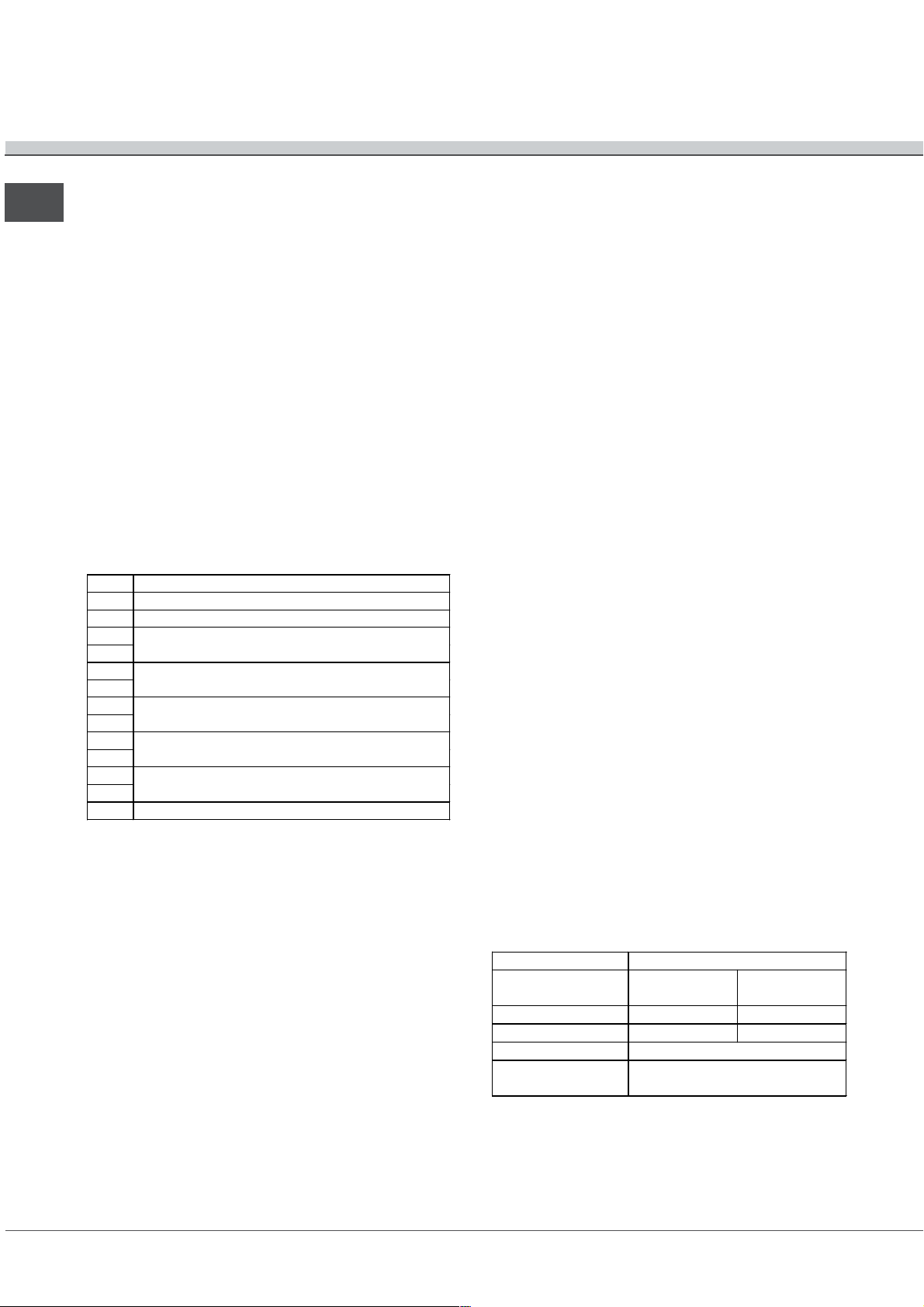
Pos Regolazione delle zone di cottura
0 spenta
1 per fare sciogliere il burro o il cioccolato
2
per scaldare i liquidi
3
4
per creme e salse
5
6
carni lesse - blanquette - entremets
7
8
pasta - riso
9
10
bistecche - pesce - omelette
11
12 frittura
La spia di funzionamento
Risulta accesa quando sia stata messa in funzione
una zona riscaldante.
La spia calore residuo
Indica che, una o più zone di cottura, sono a
temperatura superiore a 60°C anche dopo lo
spegnimento delle zone di cottura.
Descrizione tecnica delle zone di
cottura
In queste tabelle sono riportati, modello per
modello, i valori di assorbimento energetico, il tipo
di elemento riscaldante e il diametro di ciascuna
zona di cottura.
PIANI COTTURA TEM 748 L
Zone di cottura
Posteriore centro H 1200 W 145
Anteriore centro AD 1050/2500 210/140
Potenza max totale 3700
Potenza
(in W)
AD = alogena doppio
H = hilight singolo
Diametro
(in mm)
10
Page 11
Precauzioni e consigli
Lapparecchio è stato progettato e costruito
in conformità alle norme internazionali di sicurezza.
Queste avvertenze sono fornite per ragioni di sicurezza
e devono essere lette attentamente.
Questa apparecchiatura è conforme alle
seguenti Direttive Comunitarie: 2006/95/CEE
del 12/12/06 (Bassa Tensione) e successive
modificazioni - 89/336/CEE del 03/05/89 (Compatibilità
Elettromagnetica) e successive modificazioni - 93/68/
CEE del 22/07/93 e successive modificazioni. 90/336/
CEE del 29/06/90 (Gas) e successive modificazioni.
2002/96/CE
Sicurezza generale
Questo apparecchio riguarda un apparecchio da
incasso di classe 3.
Gli apparecchi gas necessitano, per un corretto
funzionamento, di un regolare ricambio daria.
tarsi che nella loro installazione siano
Accer
rispettati i requisiti richiesti nel paragrafo relativo
al Posizionamento.
Le istruzioni s
destinazione i cui simboli figurano sul libretto e
sulla targa matricola.
Lapparecchio è stato concepito per un uso di tipo
non professionale allinterno dellabitazione.
Lapparecchio non va installato allaperto, nemmeno
se lo spazio è riparato, perché è molto pericoloso
lasciarlo esposto a pioggia e temporali.
Non toccare la macchina a piedi nudi o con le mani
o i piedi bagnati o umidi.
Assicurarsi sempre che le manopole siano nella
posizione l
utilizzato.
Lapparecchio deve essere usato per cuocere
alimenti, solo da persone adulte e secondo le
istruzioni riportate in questo libretto. Non utilizzare il
piano come superficie di appoggio, né come
tagliere.
Il piano in vetroceramica è resistente agli urti
meccanici, tuttavia può incrinarsi (o eventualmente
frantumarsi) se colpito con un oggetto appuntito,
quale un utensile. In questi casi, scollegare
immediatamente lapparecchio dalla rete di
alimentazione e rivolgersi allAssistenza.
Se la superficie del piano è incrinata, spegnere
l'apparecchio per evitare la possibilità di scosse
elettriche.
ono valide solo per i paesi di
/¡ quando lapparecchio non è
Evitare che il cavo di alimentazione di altri
elettrodomestici entri in contatto con parti calde del
piano cottura.
Non dimenticare che la temperatura delle zone di
cottura rimane piuttosto elevata per almeno trenta
minuti dopo lo spegnimento. Il calore residuo è
segnalato anche da un indicatore (vedi Avvio e utilizzo).
Tenere a debita distanza dal piano cottura qualsiasi
oggetto che potrebbe fondere, ad esempio oggetti
in plastica, in alluminio o prodotti con un elevato
contenuto di zucchero. Fare particolare attenzione a
imballaggi e pellicole in plastica o alluminio: se
dimenticati sulle superfici ancora calde o tiepide
possono causare un grave danno al piano.
Assicurarsi che i manici delle pentole siano sempre
rivolti verso linterno del piano cottura per evitare
che vengano urtati accidentalmente.
Non staccare la spina dalla presa della
correntetirando il cavo, bensì afferrando la spina.
Non
Se presenti, non guardare a lungo le zone di
Evitare che i bambini giochino con l'apparecchio.
Non è previsto che l'apparecchio venga utilizzato da
fare pulizia o manutenzione senza aver prima
staccato la spina dalla rete elettrica.
cottura alogene.
persone (bambini compresi) con ridotte capacità
fisiche, sensoriali o mentali, da persone inesperte o
che non abbiano familiarità con il prodotto, a meno
che non vengano sorvegliate da una persona
responsabile della loro sicurezza o non abbiano
ricevuto istruzioni preliminari sull'uso
dell'apparecchio.
Smaltimento
Smaltimento del materiale di imballaggio: attenersi
alle norme locali, così gli imballaggi potranno essere
riutilizzati.
La direttiva Europea 2002/96/CE sui rifiuti di
apparecchiature elettriche ed elettroniche (RAEE),
prevede che gli elettrodomestici non debbano
essere smaltiti nel normale flusso dei rifiuti solidi
urbani. Gli apparecchi dismessi devono essere
raccolti separatamente per ottimizzare il tasso di
recupero e riciclaggio dei materiali che li
compongono ed impedire potenziali danni per la
salute e lambiente. Il simbolo del cestino barrato è
riportato su tutti i prodotti per ricordare gli obblighi
di raccolta separata.
Per ulteriori informazioni, sulla corretta dismissione
degli elettrodomestici, i detentori potranno rivolgersi
al servizio pubblico preposto o ai rivenditori.
IT
11
Page 12
Manutenzione e cura
Escludere la corrente elettrica
IT
Prima di ogni operazione isolare lapparecchio dalla
rete di alimentazione elettrica.
Pulire lapparecchio
Evitare luso di detergenti abrasivi o corrosivi, quali i
prodotti in bombolette spray per barbecue e forni,
smacchiatori e prodotti antiruggine, i detersivi in
polvere e le spugne con superficie abrasiva: possono
graffiare irrimediabilmente la superficie.
Non utilizzare mai pulitori a vapore o ad alta
pressione per la pulizia dellapparecchio.
Per una manutenzione ordinaria, è sufficiente lavare
il piano con una spugna umida, asciugando quindi
con una carta assorbente per cucina.
Se il piano è particolarmente sporco, strofinare con
un prodotto specifico per la pulizia delle superfici in
vetroceramica, sciacquare e asciugare.
Per rimuovere gli accumuli di sporco più consistenti
servirsi dellapposito raschietto fornito in dotazione.
Intervenire non appena possibile, senza attendere
che lapparecchio si sia raffreddato, per evitare
lincrostazione dei residui. Eccellenti risultati si
possono ottenere usando una spugnetta in filo
dacciaio inossidabile - specifica per piani in
vetroceramica - imbevuta di acqua e sapone.
Telaio in acciaio inox
(solo nei modelli con cornice)
Lacciaio inossidabile può macchiarsi per effetto
di unacqua molto calcarea lasciata per un periodo di
tempo prolungato a contatto dello stesso oppure a
causa di prodotti per la pulizia contenenti fosforo. Si
consiglia di sciacquare abbondantemente e
asciugare con cura dopo la pulizia del piano. In caso
di versamenti dacqua, intervenire rapidamente
asciugando con cura.
Smontare il piano
Nel caso si renda necessario smontare il piano
cottura:
1. togliere le viti che fissano le molle di centraggio sui lati;
2. allentare le viti dei ganci di fissaggio sugli angoli;
3. estrarre il piano cottura dal vano del mobile.
Raccomandiamo di evitare di accedere ai
meccanismi interni per tentare una riparazione.
In caso di guasto, contattare lAssistenza.
Manutenzione rubinetti gas
Con il tempo può verificarsi il caso di un rubinetto che
si blocchi o presenti difficoltà nella rotazione, pertanto
sarà necessario provvedere alla sostituzione del
rubinetto stesso.
Il raschietto in dotazione è tagliente: utilizzarlo con
attenzione.
In caso sul piano cottura si fossero accidentalmente
fusi oggetti o materiali quali plastica o zucchero,
rimuoverli con il raschietto immediatamente, finché
la superficie è ancora calda.
U
na volta pulito, il piano può essere trattato con
un prodotto specifico per la manutenzione e la
protezione: la pellicola invisibile lasciata da questo
prodotto protegge la superficie in caso di
scolamenti durante la cottura. Si raccomanda
di eseguire queste operazioni con lapparecchio
tiepido o freddo.
Ricordarsi sempre di risciacquare con acqua pulita
e asciugare accuratamente il piano: i residui di
prodotti potrebbero infatti incrostarsi durante la
successiva cottura.
Nei piani dotati di accensione automatica occorre
procedere frequentemente ad una accurata pulizia
della parte terminale dei dispositivi di accensione
istantanea elettronica e verificare che i fori di uscita
del gas non siano ostruiti;
Questa operazione deve essere effettuata da un
tecnico autorizzato dal costruttore.
12
Page 13
Anomalie e rimedi
Può accadere che il piano non funzioni o non funzioni bene. Prima di chiamare l'assistenza, vediamo che cosa
si può fare. Innanzi tutto verificare che non ci siano interruzioni nelle reti di alimentazione gas ed elettrica, ed in
particolare i rubinetti gas a monte del piano siano aperti.
IT
Anomalie
Il bruciatore non si accende o la fiamma
non è uniforme.
La fiamma non rimane accesa nelle versioni
con sicurezza.
Il bruciatore in posizione di m
rimane acceso.
I recipienti sono instabili.
Le griglie sono state invertite.
Se, nonostante tutti i controlli, il piano non funziona e l'inconveniente da voi rilevato persiste, chiamate il Centro
Assistenza Tecnica. Comunicare:
il modello della macchina (Mod.)
il numero di serie (S/N)
Queste ultime informazioni si trovano sulla targhetta caratteristiche posta sullapparecchio e/o sullimballo.
inimo non
Possibili cause / Soluzione:
Sono ostruiti i fori di uscita del gas del bruciatore.
Sono montate correttamente tutte le parti mobili che
compongono il bruciatore.
Ci sono correnti d'aria nelle vicinanze del piano.
Non avete premuto a fondo la manopola.
Non avete mantenuto premuta a fondo la manopola per
un tempo sufficiente ad attivare il dispositivo di
sicurezza.
Sono ostruiti i fori di fuoriuscita del gas in
corrispondenza del dispositivo di sicurezza.
Sono ostruiti i fori di fuoriuscita del gas.
Ci sono correnti d'aria nelle vicinanze del piano.
La regolazione del minimo non è corretta.
Il fondo del recipiente è perfettamente piano.
Il recipiente è centrato sul bruciatore o sulla piastra
elettrica.
Non ricorrete mai a tecnici non autorizzati e rifi
originali.
utate sempre l'installazione di pezzi di ricambio non
Assistenza Attiva 7 giorni su 7
Se nasce il bisogno di assistenza o manutenzione basta chiamare il Numero Unico Nazionale 199.199.199* per
essere messi subito in contatto con il Centro Assistenza Tecnica più vicino al luogo da cui si chiama.
È attivo 7 giorni su 7, sabato e domenica compresi, e non lascia mai inascoltata una richiesta.
*Al costo di 14,26 centesimi di Euro al minuto(iva inclusa) dal Lun. al Ven. dalle 08:00 alle 18:30, il Sab. dalle
08:00 alle 13:00 e di 5,58 centesimi di Euro al minuto (iva inclusa) dal Lun. al Ven. dalle 18:30 alle 08:00, il Sab.
dalle 13:00 alle 08:00 e i giorni festivi, per chi chiama da telefono fisso.
Per chi chiama da radiomobile le tariffe sono legate al piano tariffario delloperatore telefonico utilizzato.
Le suddette tariffe potrebbero essere soggette a variazione da parte delloperatore telefonico; per maggiori
informazioni consultare il sito www.scholtes.com
13
Page 14
Operating Instructions
HOB
GB
IT FR
Italiano, 1
GB
English,14
DENL
Deutsch, 55Nederlands,
41
TEM 748 L
Français, 27
Contents
Installation, 15-20
Positioning
Gas connection
Burner and nozzle specifications
Electrical connection
Description of the appliance, 21
Control panel
Start-up and use, 22-23
Practical advice on using the burners
Practical advice on using the appliance
Description of the heating elements
Technical description of the models
Precautions and tips, 24
General safety
Disposal
Maintenance and care, 25
Switching the appliance off
Cleaning the appliance
Removing the hob
Gas tap maintenance
Troubleshooting , 26
Page 15
Installation
Before operating your new appliance please read this
instruction booklet carefully. It contains important information
for safe use, installation and care of the appliance.
Please keep these operating instructions for future
reference. Pass them on to possible new owners of the
appliance.
Positioning
Keep packaging material out of the reach of children. It
can become a choking or suffocation hazard (see
Precautions and tips).
The appliance must be installed by a qualified professional
according to the instructions provided. Incorrect installation
may cause harm to people and animals or may damage
property.
This unit may be installed and used only in permanently
ventilated rooms in accordance with British Standard Codes
Of Practice: B.S. 6172 / B.S. 5440, Par. 2 and B.S. 6891
Current Editions. The following requirements must be
observed:
The room must be equipped with an air extraction
system that expels any combustion fumes. This may
consist of a hood or an electric fan that automatically
starts each time the appliance is switched on
The room must also allow proper air circulation, as air is
.
Liquid petroleum gas sinks to the floor as it is heavier
than air. Therefore, rooms containing LPG cylinders
must also be equipped with vents to allow gas to
escape in the event of a leak. As a result LPG
cylinders, whether partially or completely full, must not
be installed or stored in rooms or storage areas that are
below ground level (cellars, etc.). It is advisable to
keep only the cylinder being used in the room,
positioned so that it is not subject to heat produced by
external sources (ovens, fireplaces, stoves, etc. ) which
could raise the temperature of the cylinder above 50°C.
Fitting the app
liance
Use the appropriate cabinet to ensure that the appliance
functions properly.
The supporting surface must be heat-resistant up
to a temperature of around 100°C
if the appliance is to be installed above an oven,
the oven must have a forced ventilation cooling
system
avoid installing the hob above
a dishwasher: if
this cannot be avoided, place a waterproof
separation device between the two appliances
depending on the hob you want to install the
cabinet must have the following dimensions (see
figure):
GB
In a chimney stack or branched flue.
(exclusively for cooking appliances)
Directly to
the Outside
needed for combustion to occur normally. The flow of air
3
must not be less than 2 m
/h per kW of installed power.
The air circulation system may
take air directly from the outside by
means of a pipe with an inner
cross section of at least 100 cm
A
Examples of ventilation holes
for comburant air.
Adjacent
Room
Room to be
Vented
the opening must not be
vulnerable to any type of
blockages.
The system can also provide the
air needed for combustion
indirectly, i.e. from adjacent rooms
fitted with air circulation tubes as
described above. However, these
rooms must not be communal
Enlarging the ventilation slot
between window and floor.
rooms, bedrooms or rooms that
may present a fire hazard.
690
48
560 +/- 1
520
490 +/- 1
Kitchen cabinets adjacent to the appliance and taller
than the top of the hob must be at least 600 mm from
the edge of the hob.
2
;
Hoods must be installed according to their relative
installation instruction manuals and at a minimum
distance of 650 mm from the hob.
Place the wall cabinets adjacent to the hood at a
minimum height of 420 mm from the hob (see figure).
If the hob is installed beneath a
wall cabinet, the latter must be
600mm min.
700mm min.
situated at a minimum of 700 mm
above the hob (see figure).
540mm min.
15
Page 16
GB
Ventilation
To allow adequate ventilation and to avoid overheating
of the surrounding surfaces the hob should be positioned
as follows:
At a minimum distance of 40 mm from the back
panel.
So that a minimum distance of 20 mm is
maintained between the installation cavity and the
cabinet underneath.
min. 20 mm
5 mm
COMPARTMENT
own pin) into the lower edges of the hob, using the
long pointed screws to fix them in place, until the
glass is stuck
The screws for the alignment springs must remain
to the supporting surface.
accessible.
In order to adhere to safety standards, the
appliance must not come into contact with electrical
parts once it has been installed.
All parts which ensure the safe operation of the
appliance must not be removable without the aid of
a tool.
FRONT SIDE
OF HOB
SUPPORTING
SURFACE
30
40
min. 40 mm
min. 20 mm
5 mm
FAN-ASSISTED
OVEN
min. 40 mm
Fixing
The appliance must be installed on a perfectly level
supporting surface.
Any deformities caused by improper fixing could
affect the features and operation of the hob.
The thickness of the supporting surface
taken into account when choosing
the length of the
screws for the fixing hooks:
30 mm thick: 17.5 mm screws
40 mm thick: 7.5 mm screws
Fix the hob as follows:
1. Use short flat-bottomed screws to fix the 4
alignment springs in the holes pro
central point of each side of the hob.
2. Place the hob in the cavity, make sure it is in a
central position and push down on the whole
perimeter until the hob is stuck to the supporting
surface.
3. For ho
bs with raised sides: After inserting the hob
into its cavity, insert the 4 fixing hooks (each has its
should be
vided at the
UNDERSIDE
OF HOB
Gas connection
The appliance should be connected to the main gas
supply or to a gas cylinder in compliance with current
national regulations. Before carrying out the connection,
make sure the cooker is compatible with the gas supply
you wish to use. If this is not the case, follow the
instructions indicated in the paragraph Adapting to
different types of gas.
When using liquid gas from a cylinder, install a pressure
regulator which complies with current national regulations.
Check that the pressure of the gas supply is consistent
with the values indicated in Table 1 (Burner and nozzle
specifications). This will ensure the safe operation and
16
Page 17
longevity of your appliance while maintaining efficient
energy consumption.
Connection with a rigid pipe (copper or steel)
Connection to the gas system must be carried out in such
a way as not to place any strain of any kind on the
appliance.
There is an adjustable L-shaped pipe fitting on the
appliance supply ramp and this is fitted with a seal in order
to prevent leaks. The seal must always be replaced after
rotating the pipe fitting (seal provided with appliance). The
gas supply pipe fitting is a threaded 1/2 gas cylindrical male
attachment.
Setting the burners to minimum:
1.Turn the tap to the low flame position.
2. Remove the knob and
adjust the adjustment
screw, which is positioned
in or next to the tap pin,
until the flame is small but
steady.
GB
Connecting a flexible jointless stainle
ss steel pipe to a
threaded attachment
The gas supply pipe fitting is a threaded 1/2 gas cylindrical
male attachment.
These pipes must be installed so that they are never longer
than 2000 mm when fully extended. Once connection has
been carried out, make sure that the flexible metal pipe
does not touch any moving parts and is not compressed.
Only use pipes and seals that comply with current
national regulations.
Checking the tightness of the connection
When the installation process is complete, check the
pipe fittings for leaks using a soapy solution. Never use a
flame.
Adapting to di
fferent types of gas
To adapt the hob to a different type of gas other than
default type (indicated on the rating plate at the base of
the hob or on the packaging), the burner nozzles should
be replaced as follows:
1. Remove the hob grids and slide the burners off their
seats.
2.Unscrew the nozzles using a 7 mm socket spanner,
and replace them with nozzles for the new type of gas
(see table 1 Burner and nozzle characteristics).
3. Reassemble the parts following the above procedure in
the reverse order.
4. Once this procedure is finished, replace the old rating
sticker with one indicating the new type of gas used.
Sticker are available from any of our Service Centres.
3
. Having adjusted the flame to the required low setting,
while the burner is alight, quickly change the position of
the knob from minimum to maximum and vice versa
several times, checking that the flame does not go out.
4. Some appliances have a safety device (thermocouple)
fitted. If the device fails to work when the burners are set
to the low flame setting, increase this low flame setting
using the adjusting screw.
5. Once the adjustment has been made, replace the seals
on the by-passes using sealing wax or a similar
substance.
If the appliance is connected to liquid gas, the regulation
screw must be fastened as tightly as possible.
Once this procedure is finished, replace the old rating
sticker with one indicating the new type of gas used.
Stickers are available from any of our Service Centres.
Should the gas pressure used be different (or vary
slightly) from the recommended pressure, a suitable
pressure regulator must be fitted to the inlet pipe (in order
to comply with current national regulations).
Adjusting the burners primary air :
Does not require adjusting.
17
Page 18
GB
Burner and nozzle specifications
Table 1
Burner Diameter
(mm)
Thermal power
kW (p.c.s.*)
By-Pass
1/100
Thermal power
Ridot. (mm) Nomin (mm) *** ** Nomin (mm)
Semi Fast (S)750,40281,8067131129 1,80 102 171
Triple Crown
(TC)
Supply
Pressures
130 1,30 57 3,30 87 240 236 3,60 131 343
Nominal (mbar)
Minimum (mbar)
Maximum (mbar)
* At 15°C and 1013 mbar-dry gas
** Propane P.C.S. = 50.37 MJ/kg.
*** Butane P.C.S. = 49.47 MJ/kg.
Natural P.C.S. = 37.78 MJ/m
TC S
3
Liquid Gas Natural Gas
kW (p.c.s.*)
Nozzle
1/100
Flow*
28-30
20
35
g/h
Thermal power
kW (p.c.s.*)
37
25
45
Nozzle
1/100
Flow*
20
17
25
l/h
TEM 748 L
18
Page 19
Electrical connection
The electrical connection of the hob and any built-in
oven must be carried out separately, both for safety
purposes and to make extracting the oven easier.
Terminal board
On the lower part of the
UNDERSIDE OF HOB
Single-phase connection
appliance there is a connection
box for the different types of
electricity supply (the picture is
only an indication and is not an
exact representation of the
purchased model).
If the hob does not have a supply cable fitted, proceed
as follows:
1.Use the supply cable provided (where applicable)
or a suitable supply cable, H05VV-F or higher, with
the right dimensions (cable section: 2.5 mm).
2.To open the terminal board, insert a screwdriver
into the side tabs
of the cover (see Terminal board
picture).
3.The terminal board is designed for single-phase
connection: make sure the connection supports
between springs 1 and 2 and those between 4 and
5 are in the right position (see Single-phase
picture).
4. Position the wires according to the following
diagram and table and connect the appliance by
tightening all the screws for the springs as much as
possible.
GB
The cable provided should only be used for this type of
installation.
Mains supply characteristics:
Voltage and mains frequency
220-240V 1+N ~ 50 Hz
220-240V 2 ~ 50 Hz
Blue
Brown
Green/Yellow
If the hob has a supply cable fitted,
connect it to
the mains, using the
colours as a guide (see diagram).
Earth
Live
Neutral
L
N
Voltage and
mains
frequency
Electrical connections
Terminal
board
220-240V 1+N ~
50 Hz
220-240 V 2 ~
12345
LN
Single-
phase
50 Hz
Single-phase
2
1
U-bolt
connection support
4
3
Phase Neutral Ear th
5
5. Secure the power supply cable by fastening the
clamp screw and put the cover back on.
19
Page 20
GB
Other types of connection
The cable provided is not suitable for the following
types of installation.
5. Secure the power supply cable by fastening the
clamp screw then put the cover back on.
Connecting the supply cable to the mains
If the mains supply corresponds with one of the
following:
Voltage and mains frequency
400V 3 - N ~ 50 Hz
400V 2 - N ~ 50 Hz
240V 3 ~ 50 Hz
220 220-240V 2 + 2 - N ~ 50 Hz
proceed as follows:
1.Use a suitable supply cable, H05RR-F or higher,
with the right dimensions (cable section: 1.5 mm).
2.To open the terminal board, insert a screwdriver
into the side tabs of the cover (see Terminal board
picture).
3.Loosen the cable clamp screw and the terminal
board screws according to the type of
connection
required and position the connection supports as
shown in the following table and diagrams.
4. Position the wires according to the following table
and diagrams and connect the appliance by
tightening all the screws for the springs as much as
possible.
Voltage and
mains
freq uency
400V 3-N ~
50 Hz
400V 2-N ~
50 Hz
220-240V 3 ~ 50
Hz
220-240V 2+2-N
~ 50 Hz
2
1
4
3
Electrical connections
12345
L1 L2 L3 N
12345
L1 L2 N
12345
L1 L2 L3
12 34
L1
5
Two-phase
L2
N2N1
Two-phase
5
Terminal
board
Three-phase
400
Three-phase
400 2+N
Three-phase
230
If the appliance is being connected directly to the mains
an omnipolar circuit-breaker must be installed with a
minimum opening of 3 mm between contacts.
The installer must ensure that the correct electrical
connection has been made and that it is compliant with
regulations.
safety
Before connecting to the power supply, make sure that:
The appliance is earthed and the plug is compliant
with the law.
The socket can withstand the maximum power of the
appliance, which is indicated on the attached data
plate.
voltage is in the range between the values
The
indicated on the data plate.
The socket is compatible with the plug of the
appliance. If the socket is incompatible with the plug,
ask an authorised technician to replace it. Do not use
extension cords or
multiple sockets.
Once the appliance has been installed, the power
supply cable and the electrical socket must be easily
accessible.
The cable must not be bent or compressed.
The cable must be checked regularly and
replaced by
authorised technicians only.
The manufacturer declines any liability should these
safety measures not be observed.
Three-phase 400
2
1
4
3
5
2+N
Phase Neutral Ear thPhase Neutral
2
1
3
Phase PhasePhase Neutral Ear th
U-bolt
connection support
20
PhasePhase Neutral Earth
U-bolt
connection
support
Three-phase 230
2
4
5
Three-phase 400
1
4
3
Phase PhasePhase Earth
U-bolt
connection
support
5
Page 21
Description of the appliance
Control panel
GLASS CERAMIC
COOKING ZONE
O
G
L
E
A
N
H
DD
OO
WW
00
UU
00
BB
55
LL
22
EE
RR
GG
II
NN
Control knobs for GAS BURNERS
and GLASS
CERAMIC COOKING ZONES
GB
GAS BURNERGAS BURNER
GLASS CERAMIC COOKING
ZONE operation indicator light
SAFETY DEVICES
The glass ceramic cooking zone operation
indicator light switches on whenever the knob is
moved from the 'off' position.
GAS BURNERS differ in size and power. Use the
diameter of the cookware to choose the most
appropriate burner to cook with.
Control knobs for gas burners and glass ceramic
cooking zones are used to adjust the power or the
size of the flame.
Ignition for
GAS BURNERS
GAS BURNER ignition enables a specific burner to
be lit automatically.
SAFET
Y DEVICE stops the gas flow if the flame is
accidentally extinguished.
21
Page 22

GB
Start-up and use
The glue applied on the gaskets leaves traces of
grease on the glass. Before using the appliance, we
recommend you remove these with a special nonabrasive cleaning product. During the first few hours
of use there may be a smell of rubber which will
disappear very quickly.
The position of the corresponding gas burner or
glass ceramic cooking zone is indicated on every
knob.
Burner ø Cookware Diameter (cm)
Semi Fast (S) 16 - 20
Triple Crown (TC) 24 - 26
To identify the type of burner, refer to the designs in
the section entitled, "Burner and Nozzle
Specifications".
Gas burners
Each burner can be adjusted to one of the following
settings using the corresponding control knob:
Off
Maximum
Minimum
To light one of the burners, hold a lit match or lighter
near the burner and, at the same time, press down
and turn the corresponding knob anti-clockwise to the
maximum setting.
Since the burner is fitted with a safety device, the
knob should be pressed for approximately 2-3
seconds to allow the automatic device keeping the
flame alight to heat up.
To light a burner, simply press the corresponding
knob all the way in and then turn it in the counterclockwise direction to the "High" setting, keeping it
pressed in until the burner lights.
If a flame is accidentally extinguished, turn off the
control knob and wait for at least 1 minute before
trying to relight it.
To switch off the burner, turn the knob in a clockwise
direction until it stops (when reaches the position).
Practical advice on using the burners
Practical advice on using the appliance
To obtain the best results from your hob:
Use flat-bottomed pans to ensure that they adhere
to the cooking zone perfectly.
Always use pans with a diameter that is large
enough to cover the hotplate fully, in order to use
all the available heat.
Make sure that the bottom of the cookware is
always dry and clean to guarantee correct
adherence and long life, not only for the cooking
zones but also for the cookware itself.
Avoid using the same cookware that is used on gas
burners: the heat concentration on gas burners
may deform the base of the pan, causing it not to
adhere correctly.
Never leave a cooking zone on without cookware
on it because as it heats up and rapidly reaches
the maximum level, which could damage the
heating elements.
To ensure the burners operate efficiently:
Use appropriate cookware for each burner (see
table) so that the flames do not extend beyond the
bottom of the cookware.
Always use cookware with a flat base and a cover.
When the contents of the pan reach boiling point,
turn the knob to minimum.
22
Page 23

Description of the heating elements
The cooking zones consist of circular heating
elements. These become red a few seconds after they
have been switched on.
Halogen/mixed heating elements The hob uses
elements which consist of two halogen lamps and one
circular heating element. Thanks to this combination it
is possible to achieve optimal temperature distribution
over the entire surface of the cooking zone, while
maintaining all the advantages of halogen lamps. The
main feature of the halogen lamps is the
instantaneous emission of a large quantity of heat and
light, in practice:
rapid heating similar to that produced by a gas
burner
equally rapid switching-off.
They are extremely easy to use because they are
similar to the other heating elements. Please refer to
the table below:
Control knobs for glass ceramic cooking zones
Each cooking zone is fitted with a control knob which
can be used to continuously adjust the temperature
intensity level between a minimum of 1 and a
maximum of 12. The table lists the correspondences
between the positions indicated on the knob and the
use for which the hotplates are recommended.
Adjusting the extendable cooking zones
The extendable cooking zones (concentric or oval)
can be identified by the double heating zones on the
glass surface.
To use only the smaller zone, turn the control knob to
a position between 1 and 12, depending on the
heating power desired
To use the large zone, turn the knob to the
then set the desired power level.
Operation indicator light
.
)position,
GB
Pos Cooking zone setting
0 off
1 to melt butter or chocolate
2
to heat liquids
3
4
for creams and sauces
5
6
stews - blanquette - desserts
7
8
pasta - rice
9
10
steak - fish - omelette
11
12 fried food
This is illuminated when a heating zone has been
activated.
Residual heat indicator light
This indicates that one or more cooking zones are at a
temperature greater than 60°C, even after the cooking
zones have been switched off. Some models have 4
residual heat indicator lights, one for each cooking
zone.
Technical description of the models
This table provides a model-by-model list of the
energy absorption values, type of heating elements
(halogen or radiant elements) and diameters of each
cooking zone.
HOBS TEM 748 L
Cooking zone
Rear centre H 1200 W 145
Front centre AD 1050/2500 210/140
Maximum total
power
Power
(W)
AD = double halogen
H = single hilight
Diameter
(mm)
3700
23
Page 24

Precautions and tips
GB
This appliance has been designed and
manufactured in compliance with international safety
standards. The following warnings are provided for
safety reasons and must be read carefully.
This appliance conforms to the following
European Economic Community directives:
-2006/95/EEC dated 12/12/06 (Low Voltage) and
subsequent amendments
- 89/336/EEC dated 03/05/89 (Electromagnetic
Compatibility) and subsequent amendments
- 93/68/EEC dated 22/07/93 and subsequent
amendments.
- 90/336/EEC dated 29/06/90 (Gas) and subsequent
amendments.
- 2002/96/EC
General safety
This is a class 3 built-in appliance.
Gas appliances require regular air exchange to
maintain efficient operation. When installing
the hob, follo
paragraph on Positioning the appliance.
These instructions are only valid for the
countries whose symb
and on the serial number plate.
The appliance was designed for domestic use
inside the home and is not intended for
commercial or industrial use.
The appliance must not be installed outdoors, even
in covered areas. It is extremely dangerous to
leave the appliance exposed to rain and storms.
Do not touch the appliance with bare feet or with
wet or damp hands and feet.
Always make sure the knobs are in the l/
position when the appliance is not in use.
The appliance must be used by adults only,
according to the instructions in this manual. Do
not use the hob as a worktop or chopping board.
The glass ceramic hob is resistant to mechanical
shocks, but it may crack (or even break) if hit with
a sharp object such as a tool. If this happens,
disconnect the appliance from the electricity
mains immediately and contact a Service Centre.
If the surface of the hob is cracked, switch off the
appliance to prevent electric shocks from
occurring.
Ensure that power supply cables of other
electrical appliances do not come into contact
with the hot parts of the hob.
Remember that the cooking zones remain
relatively hot for at least thirty minutes after the
cooking zones have been switched off. An
w the instructions provided in the
ols appear in the manual
¡
indicator light provides a warning when residual
heat is present (see Start-up and use).
Keep any object that could melt away from the
hob, for example plastic and aluminium objects,
or products with a high sugar content. Be
especially careful when using plastic and
aluminium film and packaging: if placed on
surfaces that are still hot, they may cause serious
damage to the hob
Always make sure that pan handles are turned
towards the centre of the hob in order to avoid
accidental burns.
When unplugging the appliance always pull the plug
from the mains socket, do not pull on the cable.
Never carry out any cleaning or maintenance work
without having detached the plug from the mains.
Do not look at the halogen lamps in the
cooking zones for long if they are present.
The appliance should not be operated by people (including
children) with reduced physical, sensory or mental capacities,
by inexperienced individuals or by anyone who is not familiar
with the product. These individuals should, at the very least,
be supervised by someone who assumes responsibility for their
safety or receive preliminary instructions relating to the
operation of the appliance.
Do not let children play with the appliance.
.
Disposal
When disposing of packaging material: observe
local legislation so that the packaging may be
reused.
The European Directive 2002/96/EC on Waste
Electrical and Electronic Equipment (WEEE),
requires that old household electrical appliances
must not be disposed of in the normal unsorted
municipal waste stream. Old appliances must be
collected separately in order to optimise the
recovery and recycling of the materials they contain
and reduce the impact on human health and the
environment. The crossed out wheeled bin
symbol on the product reminds you of your
obligation, that when you dispose of the appliance
it must be separately collected.
Consumers may take their old appliance to public
waste collection areas, other communal collection
areas, or if national legislation allows return it to a
retailer when purchasing a similar new product.
All major household appliance manufacturers are
active in the creation of systems to manage the
collection and disposal of old appliances.
24
Page 25

Maintenance and care
Switching the appliance off
Disconnect your appliance from the electricity supply
before carrying out any work on it.
Cleaning the appliance
Do not use abrasive or corrosive detergents (for
example, products in spray cans for cleaning
barbecues and ovens), stain removers, anti-rust
products, powder detergents or sponges with
abrasive surfaces: these may scratch the surface
beyond repair.
Never use steam cleaners or pressure cleaners on
the appliance.
It is usually enough to wash the hob with a damp
sponge and dry it with absorbent kitchen roll.
If the hob is particularly dirty, rub with a special
glass ceramic cleaning product, rinse and dry.
To remove more stubborn dirt, use the scraper
provided. Remove spills as soon as possible,
without waiting for the appliance to cool, to avoid
residues forming crusty deposits. You can obtain
excellent results by using a rust-proof steel wire
sponge - specifically designed for glass ceramic
surfaces - soaked in soapy water.
Stainless steel frame (only in models with outer
frame)
Stainless steel can be marked by hard water that has
been left on the surface for a long time, or by cleaning
products containing phosphorus.
After cleaning, it is advisable to rinse the surface well
and dry it thoroughly. If water is spilt on the surface,
dry it quickly and thoroughly
Frame made of aluminum with an aspect steel. Dont
use products of cleaning and spot remover forbidden
for aluminium.
.
Removing the hob
If it is necessary to remove the hob:
1.Loosen the screws fixing the alignment springs on
each side.
2.Loosen the screws holding the fixing hooks in each
corner.
3.Take the hob out of its installation cavity.
Do not attempt to repair the appliance yourself. If
the appliance breaks down, contact a Service Centre.
Gas tap maintenance
Over time, the taps may become jammed or difficult to
turn. If this happens, the tap must be replaced.
GB
The scraper provided is sharp: be careful when
using it.
If the plastic or sugary substances are accidentally
melted on the hob, remove them immediately with
the scraper, while the surface is still hot.
Once it is clean, the hob may be treated with a
special protective maintenance product: the
invisible film left by this product protects the
surface from drips during cooking. This may be
done while the appliance is warm or cold.
Always remember to rinse the appliance with clean
water and dry the hob thoroughly: residues can
become encrusted during cooking.
For hobs which ligth automatically, the terminal part
of the electronic instant lighting devices should be
cleaned frequently and the gas outlet holes should
be checked for blockages.
This procedure must be performed by a qualified
technician authorised by the manufacturer.
25
Page 26

GB
Troubleshooting
It may happen that the appliance does not function properly or at all. Before calling the service centre for
assistance, check if anything can be done. First, check to see that there are no interruptions in the gas and
electrical supplies, and, in particular, that the gas valves for the mains are open.
Problem
Possible causes/Solution
The burner does not light or the flame is not
even around the burner.
The flame dies in models with a safety
device.
The gas holes on the burner are clogged.
All the movable parts that make up the burner are
mounted correctly.
There are draughts near the appliance.
You pressed the knob all the way in.
You keep the knob pressed in long enough to activate the
safety device.
The gas holes are not blocked in the area corresponding
to the safety device.
The
burner does not remain lit when set to
minimum.
The cookware is unstable.
If, despite all these checks, the hob does not function properly and the problem persists, call the nearest Customer
Service Centre. Please have the following information handy:
The appliance model (Mod.).
The serial number (S/N).
This information can be found on the data plate located on the appliance and/or on the packaging.
Never us
e unauthorised technicians and never accept replacement parts which are not original.
The gas holes are not blocked.
There are no draughts near the appliance.
The minimum setting has been adjusted properly.
The bottom of the cookware is perfectly flat.
The cookware is positioned correctly at the centre of the
burner.
The pan support grids have been positioned correctly.
26
Page 27

Mode demploi
TABLE DE CUISSON
Italiano, 1
41
TEM 748 L
GBIT
English,14
DENL
Deutsch, 55Nederlands,
FR
Français, 27
Sommaire
Installation, 28-34
Positionnement
Raccordement gaz
Caractéristiques des brûleurs et des injecteurs
Raccordement électrique
Description de lappareil, 35
Tableau de bord
Mise en marche et utilisation, 36-37
Conseils pratiques pour lutilisation des brûleurs
Conseils dutilisation de votre appareil
Description des éléments de chauffe
Description technique
des modèles
Précautions et conseils , 38
Sécurité générale
Mise au rebut
Nettoyage et entretien, 39
Mise hors tension
Nettoyage de lappareil
Démontage de la table
Entretien robinets gaz
FR
BE
NL
Anomalies et remèdes, 40
Page 28

FR
BE
NL
Installation
Conservez ce mode demploi pour pouvoir le consulter à tout
moment. En cas de vente, de cession ou de déménagement,
veillez à ce quil suive lappareil pour informer le nouveau
propriétaire sur son fonctionnement et lui fournir les conseils
correspondants.
Lisez attentivement les instructions : elles contiennent des
conseils importants sur linstallation, lutilisation et la sécurité de
votre appareil
Les appareils réglés en usine pour (voir la plaquette
dimmatriculation et la plaquette prédisposition gaz de
lappareil):
Naturel Catégorie II2E+3+ pour la France;
gaz
gaz Naturel Catégorie II2E+3+ pour la Belgique;
gaz Naturel Catégorie I2L pour la Hollande.
Un ultérieur réglage nest donc pas nécessaire.
Conditions régl
Le raccordement gaz devra être fait par un technicien qui
assurera la bonne alimentation en gaz et le meilleur réglage de la
combustion des brûleurs. Ces opérations dinstallation, quoique
sont délicates et primordiales pour que votre table de
simples,
cuisson vous rende le meilleur service. Linstallation doit être
effectuée conformément aux textes réglementaires et règles de
lart en vigueur, notamment:
Arrêté du 2 août 1977. R
applicables aux installations de gaz combustibles et
dhydro-carbures liquéfiés situées à lintérieur des bâtiments
dhabitation et de leurs dépendances.
Norme DTU P45-204. Installations de gaz (anciennement
DTU n° 61-1-installations de gaz - Avril 1982 + additif n°1
Juillet 1984).
Règlement sanitaire départemental.
Positionnement
Les emballages ne sont pas des jouets pour enfants, il faut
les mettre au rebut en respectant la réglementation sur le tri
sélectif des déchets (voir Précautions et conseils).
Linstallation doit être effectuée par un professionnel du secteur
conformément aux instructions
installation peut causer des dommages à des personnes, des
animaux ou des biens.
Cet appareil peut être installé et fonctionner seulement dans
des locaux qui sont aérés en permanence, selon les
prescriptions des Normes:
Pour la France selon les
Pour la Belgique NBN D51-003 et NBN D51-001 en vigueur.
Pour la Hollande NEN-1078 en vigueur.
Il faut observer les conditions suivantes:
La pièce doit prévoir un système d
lextérieur des fumées de combustion, réalisé au moyen
dune hotte ou par ventilateur électrique qui entre
automatiquement en fonction dès que lon allume lappareil.
ementaires dinstallation (Pour la France)
ègles techniques et de sécurité
du fabricant. Une mauvaise
Normes Nationales en vigueur.
évacuation vers
En cas de cheminée ou conduit de fumée ramifié
(réservé aux appareils de cuisson)
La pièce doit prévoir un système
Directement
à l'externe
qui consent un apport dair
nécessaire à une régulière combustion. Le flux dair
nécessaire à la combustion ne doit pas être inférieur à 2 m
h par kW de puissance installée.
Le système peut être réalisé en
prélevant lair directement de
A
Exemples d'ouverture
de ventilation
pour l'air comburant
Local
adjacent
Local à
ventiler
lextérieur du bâtiment au moyen
dun conduit dau moins100 cm
section utile qui ne risque pas dêtre
bouché accidentellement.
Ou, de manière indirecte depuis
des locaux adjacents et équipés
2
de
dun conduit de ventilation avec
lextérieur comme susmentionné;
ces locaux ne doivent pas être des
des
Agrandissement de la fissure
entre la porte et le sol
parties communes du bâtiment,
chambres à coucher ou des locaux
à risque dincendie.
(Pour la France et la Belgique) Les gaz de pétrole liquéfiés, plus
lourds que lair, se déposent et stagnent vers le bas. Les
locaux
qui contiennent donc des bouteilles de G.P.L doivent prévoir
des ouvertures vers lextérieur afin de permettre lévacuation du
gaz par le bas en cas de fuites accidentelles. Les bouteilles de
GPL, quelles soient vides ou partiellement pleines,
ne devront
donc pas être installées ou entreposées dans des locaux qui se
trouvent au dessous du niveau du sol (caves etc.). Il est
opportun de nentreposer dans le local que la bouteille que vous
êtes en train dutiliser, placée de f
açon à ne pas être sujette à
laction directe de sources de chaleur (fours, feux de bois,
poêles etc.) qui peuvent atteindre des températures dépassant
50°C.
Encastrement
Pour garantir le bon fonctionnement de lappareil, il
faut que le meuble possède des caractéristiques bien
précises:
le matériau du plan dappui doit pouvoir résister à
une température denviron 100°C;
si vous souhaitez installer votre table de cuisson
au-dessus dun four, il faudra que ce dernier soit
équipé dun dispositif de refroidissement par
ventilation forcée;
évitez dinstaller votre table de cuisson au-dessus
dun lave-vaisselle : si cest le cas, prévoyez une
séparation étanche entre les deux appareils;
3
/
28
Page 29

selon la table de cuisson que vous souhaitez
installer (voir figures), la découpe du meuble doit
avoir les dimensions suivantes :
FR
690
48
560 +/- 1
520
490 +/- 1
Les meubles jouxtant la table, dont la hauteur dépasse celle
du plan de cuisson, doivent être placés à au moins 600 mm
du bord du plan.
Les hottes doivent être installées conformément aux
instructions reportées dans leur notice
dinstallation et à au
moins 650 mm de distance.
Les éléments hauts jouxtant la hotte doivent être placés à au
moins 420 mm de distance du plan de travail (voir figure).
En cas dinstallation de la table de
700mm min.
600mm min.
cuisson sous un él
dernier devra être monté à au moins
700 mm de distance du plan (voir
figure).
540mm min.
ément haut, ce
Aération
Pour permettre une bonne aération et pour éviter toute
surchauffe des surfaces autour de lappareil, la table de
cuisson doit être positionnée :
à au moins 40 mm de distance du mur arrière;
de manière à ce quil reste au moins 20 mm de
distance entre la découpe dencastrement et le
meuble en dessous.
min. 20 mm
5 mm
TIROIR
min. 40 mm
min. 20 mm
5 mm
CHALEUR
TOURNANTE
min. 40 mm
Fixation
Il est impératif dassurer lencastrement de lappareil
sur un plan dappui parfaitement plat.
Les déformations provoquées par une mauvaise
fixation risquent daltérer les caractéristiques de la
table de cuisson ainsi que ses performances.
La longueur de la vis
fixation doit être réglée avant leur montage
lépaisseur du plan dappui :
épaisseur 30 mm : vis 17,5 mm;
épaisseur 40 mm : vis 7,5 mm
de réglage des crochets de
selon
BE
NL
Pour sa fixation, procéder comme suit :
1. Se servir des vis courtes sans pointe pour visser
les 4 ressorts de centrage dans les trous
prévus sur
chaque côté de la table, en leur milieu;
2. insérer la table de cuisson dans la découpe
prévue, bien au centre et bien appuyer tout autour
du cadre pour que la table adhère parfaitement au
plan dappui.
3. pour les tables avec profils latéraux : après avoir
encastré la table de cuisson dans la découpe,
insérer les 4 crochets de fixation (chacun avec son
goujon) sur le périmètre inférieur de la table
de
cuisson et visser avec les vis longues à pointe
jusquà ce que le verre adhère bien au plan dappui.
Il faut absolument que les vis des ressorts de
centrage soient accessibles.
29
Page 30

FR
BE
NL
Conformément aux normes de sécurité, après
encastrement de lappareil, il ne doit plus y avoir
possibilité de contact avec les parties électrifiées.
Toutes les parties qui servent de protection doivent
être fixées de manière à ne pouvoir être enlevées
quavec laide dun outil.
CÔTÉ AVANT DE LA
TABLE DE CUISSON
PLAN DE
TRAVAIL
TABLE DE CUISSON
RETOURNÉE
30
40
Pour la
Belgique - la Hollande
Raccorder lappareil à la canalisation du gaz
conformément aux normes en vigueur (pour la Belgique
NBN D04-002) uniquement après avoir vérifié que
lappareil est bien réglé pour le type de gaz dalimentation
utilisé. Dans le cas contraire, (pour la Belgique) effectuer
les opérations décrites au paragraphe Adaptation aux
différents types de gaz. Pour lalimentation en gaz
liquide, utiliser des régulateurs de pression conformes
aux Normes en vigueur. Pour relier lappareil à la
canalisation du gaz Naturel, II2E+3+ pour la Belgique, I2L
pour la Hollande, il faut avant tout installer le raccord
R
(disponible sur demande auprès du Service dAssistance
Technique Ariston) avec son étanchéité G sur le raccord
en forme de L situé sur le tuyau de raccordement gaz
(voir figure). Le raccord est fourni de filetage conique mâle
avec pas 1/2 gaz.
Le raccordement doit être réalisé au moyen:
- ou dun tuyau rigide (pour la Belgique selon les Normes
NBN D51-003
- ou dun tuyau flexible en acier inox, sans interruption, et
équipé de raccordements filetés.
En amont de lappareil il faut installer un robinet darrêt du
gaz (pour la Belgique marqué A.G.B); il devra être installé
de maniè
re à pouvoir facilement le manoeuvrer. Pour la
Hollande selon les Normes Nationales en vigueur.
Raccordement gaz
Pour la France
Raccorder lappareil à la bouteille ou à la canalisation du
gaz conformément aux normes en vigueur, uniquement
après avoir vérifié que lappareil est bien réglé pour le type
de gaz dalimentation utilisé. Dans le cas contraire, effectuer
les opérations décrites au paragraphe Adaptation aux
différents types de gaz. Pour lalimentation en gaz liquide,
utiliser des régulateurs de pression conformes aux Normes
en vigueur.
Pour un fonctionnement en toute sécurité, pour lemploi
correct de lénergie et une plus longue durée de vie de
lappareil, vérifier si la pression dalimentation respecte bien
les valeurs indiquées dans le tableau 1 Caractéristiques
des brûleurs et des injecteurs.
Raccordement par tuyau rigide (cuivre ou acier)
Le raccordement à linstallation de gaz doit être effectué
de manière à ce que lappareil ne subisse aucun type de
contrainte.
La rampe dalimentation de lappareil est munie dun
raccord en L orientable dont létanchéité est assurée par
un joint. Sil vous faut inverser le raccord, vous devez
obligatoirement remplacer le joint détanchéité (fourni avec
lappareil). Le raccord dentrée du gaz à lappareil est fileté
1/2 gaz mâle cylindrique.
R
accordement par tuyau flexible en acier inox, à paroi
continue avec raccords filetés
Le raccord dentrée du gaz à lappareil est fileté 1/2 gaz
mâle cylindrique.
La mise en uvre de ces tuyaux doit être effectuée de
façon à ce que, même au maximum de leur extension, ils
ne dépassent pas 2000 mm de long. Après raccordement,
assurez-vous
que le tuyau métallique flexible ne touche
pas à des parties mobiles et nest pas écrasé.
Nutilisez que des tuyaux conformes et des joints
détanchéité conformes aux textes réglementaires
applicables dans le pays.
Vérification de létanchéité
Une fois linstallation terminée, vérifier létanchéité de
tous les raccords en utilisant une solution savonneuse et
jamais une flamme.
30
Page 31

Adaptation aux différents types de gaz (pour la France
et la Belgique)
Pour adapter la table à un type de gaz autre que celui
pour lequel elle a été prévue (indiqué sur létiquette fixée
sous la table ou sur lemballage), il faut changer les
injecteurs des brûleurs en procédant comme suit :
1. enlevez les grilles du plan de cuisson et sortez les
brûleurs de leur logement.
2. dévissez les injecteurs à laide dune clé à tube de 7 mm
et remplacez-les par les injecteurs adaptés au nouveau
type de gaz (
brûleurs et des injecteurs).
3. remontez les différentes parties en effectuant les
opérations dans le sens inverse.
4. en fin dopération remplacez la vieille étiquette par celle
correspondant au nouveau gaz utilisé, disponible dans
nos Services Après-vente.
Réglage de lair primaire des brûleurs (pour la France et
la Belgique)
Les brûleurs ne nécessitent daucun réglage de lair
primaire.
voir tableau 1 Caractéristiques des
Regolazione minimi (pour la France e la Belgique)
1. Placez le robinet sur la position de minima;
2. Déposez la manette et
tournez la vis de réglage
positionnée à lintérieur ou
sur le côté de la tige du
robinet jusquà ce que
vous obteniez une petite
flamme régulière;
3.Une fois obtenu le débit minimal souhaité, allumez le
brûleur et tournez brusquement la manette de la
position de ralenti à la position douverture maximale et
vice versa à plusieurs reprises. Vérifiez ainsi quil ny ait
pas extinction du brûleur.
4. En cas de mauvais fonctionnement du dispositif de
sécurité gaz (thermocouple) équipant certains
appareils, quand les brûleurs sont au minima,
augmentez leur débit en agissant sur la vis de réglage.
5. Après avoir proc
sur les by-pass en utilisant de la cire ou autre matériau
équivalent.
En cas de gaz liquides, il faut visser à fond la vis de
réglage.
En fin dopération remplacez la vieille étiquette par celle
correspondant au nouveau gaz utilisé, disponible dans
nos Services Après-vente.
Si la pression du gaz utilisé est différente (ou variable)
par rapport à la pression prévue, il faut installer, sur la
tuyauterie dentrée un régulateur de pression approprié
(conformément aux textes réglementaires applicables
dans le pays).
édé à ce réglage, reposez les scellés
FR
BE
NL
31
Page 32

FR
Caractéristiques des brûleurs et des injecteurs
BE
NL
Tableau 1 (pour la France et la Belgique) Gaz liquide Gaz naturel Air propané (1)
Brûleur à gaz Diamètre
Semi Rapide (S) 75 0,40 28 1,80 67 131 136 1,80 102 171 199 1, 80 183 252
Triple Couronne
(TC)
Pressions
d'alimentation
(Pour la France)
Pressions
d'alimentation
(Pour la Belgique)
(1) Seulement pour la France, voir la plaquette d'immatriculation de l'appareil. Pour la transf ormation à gaz air propane, demander le kit injecteurs à un centre d’assistance
technique.
Pour la
Hollande
Brûleur Diamètre
Puissance
(mm)
thermique
kW (p.c.s.*)
Réduit. (mm) Nomin. (mm) Butane Propane Nomin. (mm) G20 G25 Nomin. (mm)
130 1,30 57 3,30 87 240 236 3,60 131 343 399 3,30 300 46 2
By-Pass
1/100
Nominale (mbar)
Minimale (mbar)
Maximale (mbar)
Nominale (mbar)
Minimale (mbar)
Maximale (mbar)
Puissance
thermique
kW (p.c.s.*)
Inject eur
1/100
28-30
20
35
28-30
20
35
Debit*
g/h
37
25
45
37
25
45
Puissance
thermique
kW (p.c.s.*)
Inject eur
1/100
20
17
25
20
15
25
Debit*
l/h
25
20
30
25
15
30
Puissance
thermique
kW (p.c.s.*)
Inject eur
1/100
-
-
-
Debit*
8
6
15
Gaz Naturels
(mm)
Puissance thermique
kW (p.c.s. *)
Injecteur
1/100 (mm)
Débit*
(l/h)
l/h
Nominal Réduit G 25
Semi Rapide (S) 75 1,80 0,40 102 199
Triple Couronne (TC) 130 3,60 1,30 131 399
Pression
de
alimentation
Nominale (mbar)
Minimum (mbar)
Maximum (mbar)
25
20
30
* A 15°C et 1013 mbar-gaz sec
** Propane P.C.S. = 50,37 MJ/kg
*** Butane P.C.S. = 49,47 MJ/kg
Naturele G20 P.C.S. = 37,78 MJ/m
Naturele G25 P.C.S. = 32,49 MJ/m
Air Propané P.C.S. = 25,72 MJ/m
TC S
TEM 748 L
32
3
3
3
Page 33

Raccordement électrique
Le branchement électrique de la table de cuisson et celui
dun éventuel four à encastrer doivent être effectués
séparément, pour des raisons de sécurité électrique et
pour pouvoir démonter plus facilement le four en cas de
besoin.
Bornier
TABLE DE CUISSON
RETOURNEE
Raccordement monophasé
Le câble éventuellement fourni nest prévu que pour
ce type dinstallations
Caractéristiques de linstallation électrique :
Tension type et fréquence réseau
220-240V 1+N ~ 50 Hz
220-240V 2 ~ 50 Hz
Bleu
Marron
Vert / Jaune
Lappareil est équipé, sur le
dessous, dun boîtier de
raccordement à plusieurs
types dalimentation électrique
(la figure nest quindicative,
elle peut ne pas correspondre
au modèle acheté).
.
Si la table est équipée dun câble
dalimentation déjà raccordé,
branchez-le au réseau en
respectant la couleur des fils
comme illustré dans le schéma cicontre.
Si la table nest pas équipée dun câble
dalimentation raccordé, procédez comme suit :
1.Utilisez le câble dalimentation fourni (si prévu) ou
un câble dalimentation approprié, type H05VV-F ou
supérieur, aux dimensions adéquates (section
câble : 2,5 mm).
2. Faites levier à laide dun tournevis sur les
languettes du couvercle du bornier et ouvrez-le
(voir figure Bornier).
3.Le bornier est déjà prévu pour raccordement
monophasé: assurez-vous que les cavaliers de
raccordement entre les bornes 1 et 2 et ceux entre
les bornes 4 et 5 sont bien positionnés (voir figure
Monophasé).
4. Positionnez les fils conformément aux indications
de la figure et du tableau ci-dessous et procédez
au raccordement en serrant à fond toutes les vis
des bornes.
Tension type
et fréquence
réseau
Raccordements
électriques
Bornier
220-240V 1+N ~
50 Hz
220-240 V 2 ~
12345
Monophasé
LN
50 Hz
2
4
Monophasé
FR
BE
NL
Neutre
N
Phase
L
Terre
1
3
PhaseCavalier Neutre Terre
5
5. Fixez le câble dalimentation dans le serre-câble
correspondant et fermez le couvercle.
33
Page 34

FR
BE
NL
Autres types de branchement
Le câble éventuellement fourni nest pas prévu pour
ces types dinstallation.
Si linstallation électrique correspond à une des
caractéristiques suivantes :
Tension type et fréquence réseau
400V 3 - N ~ 50 Hz
400V 2 - N ~ 50 Hz
220-240V 3 ~ 50 Hz
220-240V 2 + 2 - N ~ 50 Hz
procédez comme suit :
1.Utilisez un câble dalimentation approprié, type
H05VV-F ou supérieur, aux dimensions adéquates
(section câble: 1,5 mm).
2. Faites levier à laide dun tournevis sur les
languettes du couvercle du bornier et ouvrez-le
(voir figure Bornier).
3. Dévissez la vis du serre-câble et les vis des bornes
correspondant au type de raccordement
nécessaire et positionnez les cavaliers de
raccordement conformément aux indications du
tableau et des figures ci-dessous.
4. Positionnez les fils conformément aux indications
du tableau et des figures ci-dessous et procédez
au raccordement en serrant à fond toutes les vis
des bornes.
Tension type
et fréquence
réseau
400V 3-N ~
50 Hz
400V 2-N ~
50 Hz
220-240V 3 ~ 50
Hz
220-240V 2+2-N
~ 50 Hz
Raccordements
électriques
12345
L1 L2 L3 N
12345
L1 L2 N
12345
L1 L2 L3
12 34
L1
Triphasé 400
Triphasé 230
5
Biphasé
L2
N2N1
Bornier
Triphasé 400
2+N
5
. Fixez le câble dalimentation dans le serre-câble
correspondant et fermez le couvercle.
Branchement du câble dalimentation au réseau
électrique
En cas de raccordement direct au réseau, il faut
intercaler entre lappareil et le réseau un interrupteur à
coupure omnipolaire ayant au moins 3 mm
décartement entre les contacts.
Linstallateur est responsable du bon raccordement
électrique de lappareil et du respect des normes de
sécurité.
Avant de procéder au branchement, assurez-vous
que :
la prise est bien munie dune terre conforme à la loi;
la prise est bien apte à supporter la puissance
maximale de lappareil, indiquée sur la plaquette
signalétiq
ue de lappareil;
la tension dalimentation est bien comprise entre les
valeurs indiquées sur la plaquette signalétique;
la prise est bien compatible avec la fiche de
lappareil. Si ce nest pas le cas, remplacez la prise
ou la fiche, nutilisez ni rallonges ni prises multiples.
Après installation de lappareil, le câble électrique et
la prise de courant doivent être facilement
accessibles
Le câble ne doit être ni plié ni excessivement
écrasé.
Le câble doit être contrôlé périodiquement et ne
peut être remplacé que par un technicien agréé.
! Nous déclinons toute res
ponsabilité en cas de
non respect des normes énumérées ci-dessus.
2
Phase Neutre TerrePhase Neutre
2
Phase Cavalier Neutre TerrePhase
4
1
3
4
1
3
Phase
34
Biphasé
5
Phase NeutreCavalier TerrePhase
4
2
1
3
5
Triphasé 400
4
2
5
1
3
Phase Phase
Cavalier
5
Ter r ePhase
Triphasé 400 2+N
Triphasé 230
Page 35

Description de lappareil
Tableau de bord
FR
FOYER
VITROCERAMIQUE
O
G
L
E
A
N
H
DD
OO
WW
00
UU
00
BB
55
LL
22
EE
RR
GG
II
NN
Manettes de commande
des BRULEURS GAZ et
des FOYERS VITROCERAMIQUES
BE
NL
BRULEUR GAZBRULEUR GAZ
Voyant de fonctionnement
FOYER VITROCERAMIQUE
DISPOSITIF DE
SÉCURITÉ
Le voyant de FONCTIONNEMENT FOYER
VITROCERAMIQUE s'allume dès que la manette
n'est plus sur la position éteint.
BRÛLEURS GAZ ils ont plusieurs dimensions et
puissances. Choisissez celui qui correspond le
mieux au diamètre de votre casserole.
Manettes de commande des BRULEURS GAZ et
du FOYER VITROCERAMIQUE pour le réglage de
la flamme ou de la puissance.
Bougie dallumage des BRÛLEURS
GAZ
La bougie dallumage des BRÛLEURS GAZ permet
lallumage automatique du brûleur sélectionné.
DISPOS
ITIF DE SÉCURITÉ en cas dextinction
accidentelle de la flamme, coupez immédiatement
larrivée du gaz.
35
Page 36

Mise en marche et
utilisation
FR
BE
NL
La colle utilisée pour les joints laisse des traces de
graisse sur le verre. Nous vous conseillons de les
éliminer avant dutiliser lappareil, à laide dun produit
dentretien non abrasif. Une odeur de caoutchouc
peut se dégager au cours des premières heures
dutilisation, elle disparaîtra très vite.
La position du brûleur gaz ou du foyer
vitrocéramique correspondant est indiquée sur
chaque manette.
Brûleurs à gaz
Chaque manette permet de régler le brûleur
sélectionné comme suit:
Eteint
Maximum
Minimum
Pour allumer un brûleur, approchez une flamme ou un
allume-gaz, appuyez à fond et tournez la manette
correspondante dans le sens inverse des aiguilles
dune montre pour sélectionner la position de
puissance maximale.
Sur les modèles équipés dun dispositif de sécurité
gaz, appuyez pendant au moins 2-3 secondes de
suite sur la manette pour permettre au dispositif de se
réchauffer.
Pour allumer le brûleur choisi, appuyez d'abord à fond
sur la manette correspondante et tournez-la ensuite
dans le sens contraire des aiguilles d'une montre
jusqu'à la position puissance maximum, continuez à
appuyer jusqu'à ce qu'il y ait allumage.
de toujours utiliser des casseroles à fond plat et
avec couvercle.
de tourner la manette dans la position minimum au
moment de lébullition.
Brûleurs ø Récipients (cm)
Semi-rapide (S) 16 - 20
Triple Couronne (TC) 24 - 26
Pour distinguer le type de brûleur reportez-vous aux
dessins figurant dans le paragraphe "Caractéristiques
des brûleurs et des injecteurs"
Conseils dutilisation de votre appareil
Pour obtenir de meilleures performances de votre
table de cuisson :
utilisez des casseroles à fond plat pour quelles
adhèrent parfaitement à la zone de chauffe
utilisez toujours des casseroles dont le diamètre
couvre complètement la zone de chauffe de façon
à ce que toute la chaleur disponible puisse être
utilisée;
En cas dextinction accidentelle des flammes du
brûleur, tournez la manette jusquà larrêt et attendez
au moins 1 minute avant de tenter de rallumer.
Pour éteindre le brûleur tournez la manette dans le
sens des aiguilles dune montre pour la ramener en
face du symbole .
Conseils pratiques pour lutilisation
des brûleurs
Pour obtenir un meilleur rendement, noubliez pas :
dutiliser des récipients appropriés à chaque
brûleur (voir tableau) pour éviter que les flammes
ne dépassent de sous les casseroles.
36
veillez à ce que la base des casseroles soit
toujours bien sèche et propre, pour garantir un bon
contact et une longue durée de vie des foyers mais
aussi des casseroles;
évitez dutiliser les casseroles que vous utilisez sur
les brûleurs à gaz: la concentration de chaleur sur
les brûleurs à gaz peut déformer le fond de la
casserole qui perd son adhérence;
ne laissez jamais un foyer allumé sans casserole
car, dans ce cas, le niveau maximum de chaleur
est atteint très rapidement et les éléments
chauffants risquent de sendommager.
Page 37

Description des éléments de chauffe
Les éléments radiants sont constitués de résistances
circulaires. Ils deviennent rouges quelques dizaines
de secondes à peine après leur allumage.
Les foyers halogènes mixtes. La table utilise des
éléments constitués de deux lampes halogènes et
d'une résistance circulaire. Cette combinaison permet
d'obtenir une distribution optimale de la température
sur toute la surface du foyer tout en conservant tous
les avantages des lampes halogènes. Les lampes
halogènes se caractérisent principalement par
l'émission instantanée d'une grande quantité de
lumière et de chaleur, ce qui donne :
une montée en température rapide similaire à celle
d'un brûleur à gaz
une extinction tout aussi rapide
Leur mode d'emploi est extrêmement simple car c'est
le m
ême que celui des autres éléments chauffants. Se
référer au tableau suivant :
Les manettes de commande des foyers
vitrocéramique
Chaque foyer est équipé d'une manette de
commande pour un réglage continu de la température
qui va d'un minimum de 1 à un maximum de 12. Dans
le tableau vous trouverez les correspondances entre
les positions indiquées sur les manettes et l'utilisation
préconisée pour chaque foyer.
Réglage des foyers extensible
Les foyers extensibles (concentrique ou ovale) sont
reconnaissables à la présence d'une double zone de
chauffe sur le verre.
Pour n'utiliser que la petite zone, tourner la manette
de commande de 1 à 12, selon la puissance de
chauffe désirée.
Pour utiliser la grande zone, amener d'abord la
manette sur
désirée.
), puis sélectionner la puissance
s
FR
BE
NL
Pos Règlage des zones de cuisson
0 éteint
1 pour faire fondre le beurre, le chocolat
2
pour réchauffer les liquides
3
4
pour crèmes et sauces
5
6
pot au feu - blanquette - entremets
7
8
pâtes - riz
9
10
steack - poisson - omelette
11
12 friture
Le voyant de fonctionnement
Il s'allume quand un foyer est activé.
Le voyant de chaleur résiduelle
Il signale une température supérieure à 60°C sur un
ou plusieurs foyers et ce même après leur extinction.
Certains modèles sont équipés de 4 voyants de
chaleur résiduelle, un pour chaque foyer.
Description technique
des modèles
Ces tableaux vous indiquent, modèle par modèle, les
valeurs dabsorption dénergie, le type délément
chauffant (halogène ou radiant) et le diamètre de
chaque foyer.
TABLES DE
CUISSON
Foyers
Arrière central H 1200 W 145
Avant central AD 1050/2500 210/140
Puissance maxi.
totale
Puissance
TEM 748 L
Diamètre
(en W)
AD = halogène double,
H = hilight simple
(en mm)
3700
37
Page 38

Précautions et conseils
FR
BE
NL
Cet appareil a été conçu et fabriqué conformément aux
normes internationales de sécurité. Ces conseils sont fournis
pour des raisons de sécurité et doivent être lus attentivement.
Cet appareil est conforme aux Directives Communautaires
suivantes :
- 2006/95/CEE du 12/12/06 (Basse Tension) et
modifications successives
- 89/336/CEE du 03/05/89 (Compatibilité Electromagnétique)
et modifications successives
- 93/68/CEE du 22/07/93 et modifications successives.
- 90/336/CEE du 29/06/90 (Gaz) et modifications successives.
- 2002/96/CEE
Sécurité générale
C e mode d emploi concerne u n appareil à
encas t rer cla sse 3.
Pou r bien fonc tionner, le s appareils à gaz
ont besoi n du n apport dair ré g ulier. Il
import a nt de vérifier lors de leur in stallat i on,
que tous le s poi nts ind i qués da n s le
paragraphe rela t i f à le u r Pos i t ionnement
so
ient respect és.
L es in s t ructions fourn ies ne sont applicables
quaux pays dont les sym boles sont reportés
dan s la notice et sur la pla
dimmat ricu l a t ion.
Cet appareil a été conçu pour un usage familial, de type
non professionnel.
Cet appareil ne doit pas être installé en extérieur, même
dans un endroit abrité, il est en effet très dangereux de le
laisser exposé à la pluie et aux orages.
Ne touchez pas à lappareil si vous êtes pieds nus ou si
vous avez les mains ou les pieds mouillés ou humides.
Contrôlez toujours que les manettes sont bien dans la
position l/
Cet appareil qui sert à cuire des aliments ne doit être utilisé
que par des adultes conformément aux instructions du
mode demploi. Nutilisez pas la table comme plan de
dépose ou comme planche à découper.
Le plan vitrocéramique résiste aux chocs mécaniques, il
peut toutefois se fendre (ou même se briser) sous leffet
dun choc provoqué par un objet pointu, tel quun ustensile
par exemple. Dans ce cas, débranchez immédiatement
lappareil du réseau électrique et adressez-vous à un
centre dassistance technique.
Si la surface de la table est fêlée, éteindre l'appareil pour
éviter tout risque d'électrocution.
Evitez q
électroménagers touche à des parties chaudes de la table
de cuisson.
Noubliez pas que la température des foyers reste assez
élevée pendant trente minutes au moins après leur
extinction. La chaleur résiduelle est aussi signalée par un
¡ quand lappareil nest pas utilisé.
ue le cordon dalimentation dautres petits
que tte
es t
voyant (voir Mise en marche et Utilisation).
Gardez à bonne distance de la table de cuisson tout objet
qui pourrait fondre, des objets en plastique ou en
aluminium par exemple, ou des produits à haute teneur en
sucre. Faites très attention aux emballages, au film
plastique et papier aluminium : au contact des surfaces
encore chaudes ou tièdes, ils risquent dendommager
gravement la table.
Faites attention à ce que les manches des casseroles
soient toujours tournés vers lintérieur de la table de
cuisson pour éviter tout risque daccident.
Ne tirez surtout pas sur le câble pour débrancher la fiche
de la prise de courant.
Neffectuez aucune opération de nettoyage ou dentretien
sans avoir auparavant débranché la fiche de la prise de
courant.
Si de s foyers ha logènes éq uipent votre
appareil, ne le s fixez pas des yeux t rop
longt emps .
Il nest pas prévu que cet appareil soit utilisé par des
personnes (enfants compris) présentant des capacités
physiques, sensorielles ou mentales réduites ou qui nont
pas le
xpérience ou les connaissances indispensables, à
moins quelles ne le fassent sous la surveillance de
quelquun responsable de leur sécurité ou quelles aient
été dûment formées sur lutilisation de lappareil.
S'assurer que les enfants ne jouent pas avec l'appareil.
Mise au rebut
Mise au rebut du matériel demballage : conformez-vous
aux réglementations locales, les emballages pourront ainsi
être recyclés.
La Directive Européenne 2002/96/CEE sur les Déchets des
Equipements Electriques et Electroniques (DEEE), exige
que les appareils ménagers usagés ne soient pas jetés
dans le flux normal des déchets municipaux. Les appareils
usagés doivent être collectés séparément afin doptimiser
le taux de récupération et le recyclage des matériaux qui
les composent et réduire limpact sur la santé humaine et
lenvironnement. Le symbole de la poubelle barrée est
apposée sur tous les produits pour rappeler les obligations
de collecte sépar
Les consommateurs pourront confier leur appareil usagé au
service de collecte des collectivités locales ou de leurs
groupements, ou si la législation nationale le permet, le
rendre au revendeur lors de lachat dun nouvel appareil
similaire.
Tous les principaux fabricants dappareils ménagers
travaillent activement dans la création et la gestion de
systèmes de collecte et denlèvement des appareils
usagés.
ée.
38
Page 39

Nettoyage et entretien
Mise hors tension
Avant toute opération de nettoyage ou dentretien
coupez lalimentation électrique de lappareil.
Nettoyage de lappareil
Nutilisez jamais de détergents abrasifs ou corrosifs,
tels que des bombes aérosols pour grilloirs et fours,
des détacheurs et dérouilleurs, des poudres à récurer
ou des éponges à surface abrasive : ils risquent de
rayer irrémédiablement la surface.
Ne nettoyez jamais lappareil avec des nettoyeurs
vapeur ou haute pression.
Pour un entretien courant, passez une éponge
humide sur la surface et séchez avec du papier
essuie-tout.
Si la table est sale, frottez avec un produit
dentretien adapté au verre vitrocéramique, rincez
et essuyez.
Pour enlever les salissures en relief, utilisez le
grattoir livré avec lappareil. Intervenez dès que
possible, nattendez pas que lappareil ait refroidi
afin déviter toute incrustation des salissures.
Lutilisation dune éponge en fil dacier inoxydable,
sp
éciale verre vitrocéramique, imprégnée deau
savonneuse donne dexcellents résultats.
Le grattoir fourni est coupant : utilisez-le avec
précaution.
Tout objet, matière plastique ou sucre ayant
accidentellement fondu sur la table de cuisson doit
être aussitôt enlevé à laide du grattoir tant que la
surface est encore chaude.
Dans le cas de tables équipées dallumage
automatique, nettoyez fréquemment et
soigneusement lextrémité des dispositifs
dallumage électronique instantané et vérifiez que
les orifices de sortie du gaz ne sont pas bouchés.
Cadre en acier inox (uniquement pour les modèles
avec encadrement)
Un contact prolongé avec une eau très calcaire ou
lutilisation de nettoyants contenant du phosphore
peuvent tacher lacier inox.
Nous conseillons de rincer abondamment et de bien
essuyer après entretien. Il est préférable déliminer
rapidement tout débordement deau sil y a lieu.
Cadre en aluminium avec un aspect inox. Ne jamais
utiliser de produits de nettoyage et degraissant non
applicable sur laluminium.
Démontage de la table
Sil vous faut démonter la table de cuisson :
1. enlevez les vis qui fixent les ressorts de centrage
sur les côtés;
2. desserrez les vis des crochets de fixation dans les
coins;
3. dégagez la table de cuisson du meuble.
Il est vivement recommandé déviter daccéder aux
mécanismes internes pour tenter une réparation. En
cas de panne, contactez le service dassistance
technique.
Entretien robinets gaz
Il peut arriver quau bout dun certain temps, un
robinet se bloque ou tourne difficilement. Il faut alors
le remplacer.
FR
BE
NL
Une fois que la table est propre, vous pouvez
appliquer un produit dentretien et de protection
spécial : celui-ci laisse un film invisible qui protège
la surface en cas de débordement accidentel.
Opérez de préférence quand lappareil est tiède ou
froid.
Prenez soin de toujours bien rincer à leau claire et
de sécher la table : les résidus des produits
pourraient en effet sincruster lors dune prochaine
cuisson
.
Cette opération doit être effectuée par un
technicien agréé par le fabricant.
39
Page 40

FR
BE
Anomalies et remèdes
Il peut arriver que lappareil ne fonctionne pas ou ne fonctionne pas très bien. Avant dappeler le service aprèsvente, voyons ensemble que faire. Vérifiez avant tout sil ny a pas de coupure de gaz ou de courant, et si les
robinets du gaz en amont de lappareil sont bien ouverts.
NL
Anomalies
Le brûleur ne sallume pas ou la flamme
nest pas uniforme.
La flamme séteint dans les versions
équipées de sécurité de flamme.
L
e brûleur séteint quand il est réglé sur la
position de minimum.
Les casseroles sont instables.
Causes / Solutions possibles
les orifices de sortie du gaz ne sont pas par hasard
bouchés.
les pièces amovibles composant le brûleur sont bien
montées correctement.
il y a des courants dair dans les environs du plan de
cuisson
vous avez bien appuyé à fond sur la manette.
vous avez bien appuyé à fond sur la manette pendant un
laps de temps suffisant pour permettre lactivation du
dispositif de sécurité.
les orifices de sortie du gaz situés en face du dispositif de
sécurité ne sont pas par hasard bouchés.
les orifices de sortie du gaz ne sont pas par hasard
bouchés
il y a des courants dair dans les environs du plan de
cuisson
les minima nont pas bien été réglés.
le fond de la casserole est parfaitement plat
la casserole est bien placée au centre du brûleur
la position des grilles na pas par hasard été inversée.
Si, malgré tous ces contrôles, votre appareil ne fonctionne toujours pas et linconvénient persiste, f
notre station technique. Indiquez-lui :
le modèle de votre appareil (Mod.)
son numéro de série (S/N)
Ces informations figurent sur la plaquette signalétique apposée sur votre appareil et/ou sur son emballage.
Ne faites jamais appel à des techniciens non agréés et refusez toujours linstallati
non originales.
on de pièces détachées
aites appel à
40
Page 41

Gebruiksaanwijzing
KOOKPLAAT
IT
Italiano, 1
NL
41
TEM 748 L
GB FR
English,14
Français, 27
DE
Deutsch, 55Nederlands,
Samenvatting
Het installeren, 42-48
Plaatsing
Gasaansluiting
Kenmerken van de branders en de straalpijpjes
Elektrische aansluiting
Beschrijving van het apparaat, 49
Algemeen aanzicht
Starten en gebruik, 50-51
Praktisch advies voor het gebruik van de branders
Praktische tips voor het gebruik van het apparaat
Beschrijving van de verwarmingselementen
Technische beschrijving
van de modellen
Voorzorgsmaatregelen en advies , 52
Algemene veiligheidsmaatregelen
Afvalverwijdering
Onderhoud en verzorging, 53
De elektrische stroom afsluiten
Schoonmaken van het apparaat
De kookplaat verwijderen
Onderhoud gaskranen
NL
BE
Storingen en oplossingen, 54
Page 42

Het installeren
NL
BE
Bewaar dit boekje zorgvuldig voor eventuele verdere
raadpleging. Wanneer u het product weggeeft, verkoopt, of
wanneer u verhuist, dient u dit boekje bij het apparaat te
bewaren zodat alle nodige informatie voorhanden blijft.
Lees de gebruiksaanwijzingen zorgvuldig door: er
staat belangrijke informatie in over installatie, gebruik
en veiligheid.
De apparaten zijn gebruiksklaar gemaakt in de fabriek
voor de functies (zie typeplaatje en plaatje van de gas
instelling van het apparaat) :
Natuurlijk gas Categorie II2E+3+ voor Belgie;
Natuurlijk gas Categorie I2L voor Nederland.
Het is dus niet nodig verdere regelingen uit te voeren.
Plaatsing
Het verpakkingsmateriaal is niet bestemd voor kinderen
en dient daarom te worden weggegooid volgens de
geldende normen voor gescheiden afvalverzameling ( zie
Voorzorgsmaatregelen en advies).
De installatie moet worden uitgevoerd door een
bevoegde installateur en volgens de instructies van
de fabrikant. Een verkeerde installatie kan schade
berokkenen aan personen, dieren of dingen.
dit apparaat mag alleen geïnstalleerd worden en
funktioneren in goed geventileerde vertrekken volgens
de voorschriften van de van kracht zijnde Normen:
NBN D51-003 e NBN D51-001 (voor België);
NEN-1078 (voor Nederland).
De volgende eisen moeten in acht genomen worden:
Het vertrek moet voor de verbrandingsrook over een
afvoersysteem naar buiten toe beschikken. Dit kan
gebeuren door middel van een afzuigkap of een
elektrische ventilator die automatisch aangaan elke
keer als het apparaat wordt aangezet.
In het gevaal van een schoorsteen of vertakte
rookleiding (gereserveerd voor fornuizen)
Rechtstreeks
naar buiten
Dit systeem kan worden
uitgevoerd door lucht direct van
buiten te onttrekken door middel
A
Voorbeelden
ventilatie-opening
voor verbrandingslucht
Aangrenzend
vertr ek
Te ventileren
vertr ek
van een buis met een doorsnede
van minstens 100 cm
2
en die
zodanig is geplaatst dat hij niet
per ongeluk verstopt kan raken.
Een andere manier is door op
indirecte wijze lucht te
onttrekken aan de
aangrenzende vertrekken die
door middel van een
Verhoging van de spleet
tussen deur en vloer
ventilatiebuis, zoals boven
beschreven, met buiten zijn
verbonden en die geen
gemeenschappelijke delen zijn van het huis en ook
geen ruimtes met hoog brandgevaar of slaapkamers.
(voor België) De gassen van vloeibaar gemaakte
gasmengsels (LPG) zijn zwaarder dan lucht en
blijven laag hangen. Om deze reden moeten
vertrekken waar LPG-flessen staan laag geplaatste
ontluchtingsopeningen hebben voor het afvoeren
van eventueel ontsnapt gas. Lege of halfvolle LPG-
flessen mogen dus niet worden geïnstalleerd of
bewaard in vertrekken die lager liggen dan de vloer
(kelders, enz.). Het is beter alleen de in gebruik
zijnde fles in het vertrek te bewaren, zodanig
geplaatst dat hij niet in rechtstreeks contact staat
met warmtebronnen (oven, open haard, kachel,
enz.) die hem tot temperaturen van meer dan 50°C
zouden kunnen brengen.
In bouw
Voor een goede werking van het apparaat moet het
keukenmeubel de juiste kenmerken hebben:
het keukenblad moet uit hittebestendig materiaal zijn
vervaardigd en een temperatuur van circa 100°C
kunnen verdragen;
als de kookplaat
moet deze zijn voorzien van een geventileerd
afkoelingssysteem;
installeer de kookplaat nooit boven een vaatwasser:
indien u dit toch doet, breng dan een waterdichte
afscheiding aan tussen de
naar gelang van het type kookplaat dat u wenst te
installeren (zie afbeeldingen), moet het
keukenmeubel de volgende afmetingen hebben:
boven een oven wordt geïnstalleerd
twee apparaten;
Het vertrek moet een luchttoevoersysteem hebben
dat dient voor de normale verbranding van het gas.
De luchttoevoer die nodig is voor een normale
verbranding moet niet minder dan 2 m
3
/h zijn per
kW geïnstalleerd vermogen.
42
Page 43

690
NL
48
560 +/- 1
520
490 +/- 1
De meubels die direct naast de kookplaat staan
en hierboven uitsteken, moeten op minstens 600
mm van de rand van de plaat staan.
Een afzuigkap moet worden geïnstalleerd volgens
de voorschriften die u kunt vinden in het
instructieboekje van de afzuigkap zelf en in ieder
geval op een afstand van minstens 650 mm.
Hang de keukenkastjes naast de kap op een
minimum hoogte van 420 mm van het keukenblad
(zie afbeelding).
Als de kookplaat onder een
keukenkastje wordt geplaatst,
600mm min.
moet deze zich op een
afstand van minstens 700 mm
van het keukenblad bevinden
700mm min.
540mm min.
(zie afbeelding ).
5 mm
5 mm
Bevestigen
min. 20 mm
LADE
min. 40 mm
min. 20 mm
HETELUCHTOVEN
min. 40 mm
BE
Ventilatie
Teneinde een correcte ventilatie te bereiken en
een oververhitting van de oppervlakken rondom het
apparaat te voorkomen, moet de kookplaat geïnstalleerd
worden op:
op een minimum afstand van 40 mm van de
achterwand;
op zodanige wijze dat er een minimum afstand
overblijft van 20 mm tussen het inbouwmeubel en
het onderstaande meubel.
Het apparaat moet op een absoluut horizontaal
oppervlak worden geïnstalleerd.
Eventuele door onjuiste installatie veroorzaakte
vervormingen kunnen de eigenschappen en de
prestaties van de kookplaat aantasten.
De lengte van de regelschroef van de
bevestigingshaken moet op basis van de dikte van het
keukenblad worden ingesteld
voordat de haken
worden gemonteerd:
als de dikte 30 mm is: schroef 17,5 mm;
als de dikte 40 mm is: schroef 7,5 mm.
Voor het bevestigen moet u als volgt te werk gaan:
1. Draai met korte, puntloze schroe
ven de 4
centreringsklemmen in de openingen in het midden
van elke zijde van het blad vast;
2. zet de kookplaat in het midden van de opening
van het keukenmeubel door gelijke druk uit te
oefenen op de hele
omtrek totdat de kookplaat
perfect aansluit op het keukenblad.
3. voor een blad met zijprofielen: nadat u de
kookplaat in het keukenmeubel heeft geplaatst moet
u de 4 bevestigingshaken aan de onderste rand van
de
kookplaat vastschroeven met gepunte, lange
schroeven, net zolang tot het glas goed aan het
blad vastzit.
43
Page 44

NL
L
G
R
BE
De schroeven van de centreringsklemmen moeten
te allen tijde bereikbaar blijven.
Volgens de veiligheidsnormen mag er geen contact
meer mogelijk zijn met de elektrische onderdelen
nadat het apparaat is ingebouwd.
Alle beschermende onderdelen moeten zodanig
worden bevestigd dat ze niet kunnen worden
verwijderd zonder gereedschap te gebruiken.
VOORZIJDE VAN
DE KOOKPLAAT
KEUKENBLAD
30
40
De aansluiting voert men uit
met behulp van:
- een onbuigbare buis (voor
Belgie volgens de normen
NBN D51-003)
-of met een flexibile buis van
roestvrij staal die in de muur
zit en voortzet met
bedradingsverbinder.
Daarbij dient het apparaat uitgerust te zijn van een
gaskraantje (voor Belgie A.G.B.) die gemakkelijk
draaibaar dient te zijn. Voor Nederland dient dit
gaskraantje aan de huidige Nationale Normen te
voldoen.
KOOKPLAAT
ONDERSTEBOVEN
Gasaansluiting
De aansluiting van het apparaat aan de gasbuizen
moet worden uitgevoerd zoals voorgeschreven door
de geldende normen, en nadat men er zeker van is
dat het fornuis is ingesteld voor het type gas dat
men gaat gebruiken. In het omgekeerde geval
(voor België) gaat u te werk zoals beschreven in
de paragraaf Aanpassing aan verschillende types
gas. Om het apparaat aan de gasbuizen aan te
sluiten (II2E+3+ voor Belgie en I2L voor Nederland),
dient men eerst de verbinder te monteren.R (Deze
is op aanvraag verkrijgbaar bij de technischeservice-dienst Ariston) Tevens dient men zijn
pakking op de verbinder G,die er uit ziet als een
L , van de voedings-struktuur te monteren. De
verbinder is gedraad: rond mannelijk 1/2 gas.
Aa
nsluiting met onbuigzame buis (koper of
staal)
De aansluiting aan de gasleiding moet zodanig
worden uitgevoerd dat het apparaat niet beweegt.
Op de voedingsstructuur van het apparaat bevindt
zich een L-vormig, richtbaar verbindingsstuk
waarvan de afdichting is verzekerd door een
pakking. Als het verbindingsstuk gedraaid moet
worden is het absoluut noodzakelijk de pakking te
vervangen (bij het apparaat geleverd). Het
verbindingsstuk waardoor het gas toegang krijgt tot
het fornuis is voorzien van schroefdraad: 1/2 gas
cilindrische schroefbout.
Aansluiting met een roestvrije stale
n flexibele
buis aan een onafgebroken wand voorzien van
aanhechtingen met schroefdraad.
Het verbindingsstuk waardoor het gas toegang krijgt
tot het fornuis is voorzien van schroefdraad: 1/2 gas
cilindrische schroefbout.
De in werking stelling van deze buizen moet
zodanig worden bewerkstelligd dat hun lengte in
uitgerolde toestand niet meer dan 2000 mm is.
Nadat de aansluiting heeft plaatsgevonden moet u
controleren dat de flexibele metalen buis niet in
contact komt met de beweegbare delen of dat hij
vastgekneld raakt.
G
ebruik uitsluitend buizen en afdichtingen die
voldoen aan de geldende landelijke normen.
Controleren gasdichtheid
Nadat het installeren heeft plaats gevonden moet
de perfecte gasdichtheid van alle
verbindingsstukken worden gecontroleerd met een
zeepoplossing en nooit met een vlam.
44
Page 45

Aanpassen aan de verschillende soorten gas
(voor België)
Voor het aanpassen van de kookplaat aan een ander
soort gas dan waarvoor hij is bestemd (aangegeven
op het typeplaatje aan de onderkant van de
kookplaat of op de verpakking), moeten de
straalpijpjes van de branders op de volgende wijze
worden vervangen:
1. verwijder de roosters van de kookplaat en schuif
de branders uit hun plaats.
2. schroef de straalpijpjes los met een steeksleutel
van 7mm en vervang ze met de straalpijpjes
geschikt voor het nieuwe type gas (zie tabel 1
Kenmerken van de branders en de straalpijpen).
3. zet de onderdelen weer op hun plaats door de
handelingen in omgekeerde volgorde uit te
voeren.
4. aan het einde van deze handelingen moet u het
oude etiket dat de gasinstelling aangeeft
vervangen met het etiket dat overeenkomt met
het nieuwe gas dat u gaat gebruiken, verkrijgbaar
bij onze Technische Service Centers.
Het regelen van de minimumstand (voor België)
1. Zet het kraantje op de minimumstand;
2. Verwijder de knop en draai
aan het regelschroefje in of
naast de spil van het kraantje
totdat u een kleine,
regelmatige vlam bereikt.
3. Controleer of de brander aanblijft als u de knop
snel van hoog naar laag draait.
4. Als bij de apparaten met een
veiligheidsmechanisme (thermo-element) dit
systeem niet werkt als de branders op de
minimum stand staan, moet u het minimum
verhogen door aan de stelschroef te draaien.
5. Als de regeling voltooid is moet u de zegels op
de bypass schroefjes weer op hun plaats brengen
met zegellak of dergelijk materiaal.
Bij vloeibaar gas moet het regelschroefje geheel
dicht worden geschroefd.
NL
BE
Regelen primaire lucht van de straalpijpjes (voor
België)
De branders hebben geen regeling van de primaire
lucht nodig.
Aan het einde van deze handelingen moet u het
oude etiket van de gasinstelling vervangen met het
etiket dat correspondeert met het nieuwe gas,
verkrijgbaar bij onze Technische Service Centers.
Als de gasdruk van het gebruikte gas verschillend
(of variabel) is dan hetgeen is voorzien, moet op de
toevoerbuis een drukteregelaar worden aangebracht
die voldoet aan de geldende landelijke normen.
45
Page 46

NL
BE
Kenmerken van de branders en de straalpijpjes
Table 1 (Voor Belgie) Vloeibaar gas Natuurlijk gas
Gaspit Doorsnee Thermisch
vermogen
kW (p.c.s.*)
Gered. (mm) Nomin. (mm) *** ** Nomin. (mm) G20 G25
Halp Snel (S) 75 0,40 28 1,80 67 131 136 1,80 102 171 199
Drievoudige
ring (TC)
Spanning
van
voeding
130 1,30 57 3,30 87 240 236 3,60 131 343 399
Table 1 (Voor Nederland) Natuurlijk gas
Gaspit Doorsnee Thermisch vermogen
Halp Snel (S) 75 0,40 1,80 102 199
Drievoudige ring (TC) 130 1,30 3,60 131 399
Spanning
van
voeding
By-Pass
1/100
Nominale (mbar)
Minimum (mbar)
Maximum (mbar)
Thermisch
vermogen
kW (p.c.s.*)
Straal.
1/100
Bereik*
28-30
20
35
g/h
37
25
45
Thermisch
vermogen
kW (p.c.s.*)
Straal.
1/100
Straal.
kW (p.c.s.*)
1/100
Gered. Nomin. (mm) G25
Nominale (mbar)
Minimum (mbar)
Maximum (mbar)
Bereik*
l/h
20
15
25
Bereik*
l/h
25
20
30
25
20
30
* Met 15°C en 1013 mbar-droog gas
** P.C.S. Propaangas = 50,37 MJ/kg
*** P.C.S. Butangas = 49,47 MJ/kg
P.C.S. Natuurlijk gas G20 = 37,78 MJ/m³
P.C.S. Natuurlijk gas G25 = 32,49 MJ/m³
TC S
TEM 748 L
46
Page 47

Elektrische aansluiting
De elektrische aansluitingen van de kookplaat en de
eventuele inbouwoven moeten apart worden uitgevoerd,
zowel om elektrische veiligheidsredenen als om de oven
eventueel eenvoudiger te kunnen verwijderen.
Klemmenbord
KOOKPLAAT
ONDERSTEBOVEN
Eenfasige aansluiting
De eventueel bijgeleverde kabel is alleen geschikt voor
dit type installatie.
Eigenschappen van het elektrische net:
Spanningstype en netfrequentie
220-240V 1+N ~ 50/Hz
220-240V 2 ~ 50/Hz
Blauw
Bruin
Groen/Geel
Aan de onderkant van het
apparaat bevindt zich een
klemmenbord voor de
verschillende types elektrische
voeding (het kan zijn dat de
afbeelding niet precies
overeenkomt met het model dat
u heeft aangeschaft).
Als de kookplaat al
beschikt over
een voedingskabel, moet u hem
aan het elektrische net verbinden
door de kabelkleuren te bevestigen
volgens het schema hiernaast.
Als de kookplaat niet voorzien is van een voedingskabel,
moet u op de
volgende wijze te werk gaan:
1.Gebruik bijgeleverde voedingskabel (waar
aanwezig) of een geschikte voedingskabel, type
H05VV-F of met een hogere waarde, met de juiste
afmetingen (diameter kabel: 2,5 mm).
2.Licht de lippen aan de zi
jkant van het deksel van
het klemmenbord op met een schroevendraaier en
open het (zie afbeelding Klemmenbord).
3. Het klemmenbord is ingesteld voor een eenfasige
aansluiting: verzeker u ervan dat de
verbindingskabels tussen de klemmetjes 1 en 2 en
die tussen de klemmetjes 4 en 5 zich in de correcte
positie bevinden (zie afbeelding Eenfase).
4. Plaats de draden zoals aangegeven in de volgende
afbeelding en tabel en stel een verbinding tot stand
door alle schroeven van de klemmetjes goed vast
te draaien.
Spanningstype
en netfrequentie
220-240V 1+N ~
50 Hz
220-240 V 2 ~ 50
Hz
Elektrische
aansluitingen
12345
Eenfase
LN
Klemmenbord
Eenfase
2
1
4
3
5
NL
BE
Neutraal
N
L
Fase
Aarde
Verbindingskabel AardeNeutraalFase
5. Bevestig de voedingskabel in de speciale
kabelklem en sluit het deksel af.
47
Page 48

NL
BE
Andere soorten aansluitingen
De eventuele bijgeleverde kabel is niet geschikt voor
dit type installatie.
Als het elektrische net overeenkomt met een van de
volgende eigenschappen:
Spanningstype en netfrequentie
400V 3 - N ~ 50/Hz
400V 2 - N ~ 50/Hz
220-240V 3 ~ 50/Hz
220-240V 2 + 2 - N ~ 50/Hz
ga dan als volgt te werk:
1.Gebruik een geschikte voedingskabel, type H05RR-
F of met een hogere waarde, met de juiste
afmetingen (diameter kabel: 1,5 mm).
2.Licht de lippen aan de zijkant van het deksel van
het klemmenbord op
met een schroevendraaier en
open het (zie afbeelding Klemmenbord).
3. Draai de schroef van de kabelklem en de
schroeven van de benodigde klemmetjes los en
bevestig de verbindingskabels volgens de
aanwijzingen van de volgende tabel en
afbeeldingen.
4. Plaats de draden zoals aangegeven in de volgende
afbeeldingen en tabel en stel een verbinding tot
stand door alle schroeven van de klemmetjes goed
vast te draaien.
Spanningstype
en netfrequentie
400V 3-N ~
50 Hz
400V 2-N ~
50 Hz
220-240V 3 ~ 50
Hz
220-240V 2+2-N ~
50 Hz
Elektrische
aansluitingen
12345
L1 L2 L3 N
12345
L1 L2 N
12345
L1 L2 L3
12 34
L1
Driefasen 400
Driefasen 230
5
Tweefasen
L2
N2N1
Klemmenbord
Driefasen
400 2+N
2
4
1
3
5
Tweefasen
5. Bevestig de voedingskabel in de speciale
kabelklem en sluit het deksel af.
Het aansluiten van de voedingskabel aan het
elektrische net
Bij een rechtstreekse aansluiting aan het net moet u
tussen het apparaat en het net een meerpolige
schakelaar aanbrengen met een minimum afstand van 3
mm tussen de contacten.
De installateur is verantwoordelijk voor een correcte
elektrische verbinding en het in acht nemen van de
veiligheidsnormen.
Voor het aansluiten moet u controleren dat:
het stopcontact geaard is en voldoet aan de geldende
normen;
het stopcontact in staat is het maximale vermogen van
het apparaat te verdragen, zoals aangegeven op het
typeplaatje dat zich op het
apparaat bevindt;
de spanning zich bevindt tussen de waarden die
staan aangegeven op het typeplaatje;
het stopcontact en de stekker overeenkomen. Als dat
niet zo is, dient u ofwel de stekker ofwel het
stopcontact te v
ervangen; gebruik geen
verlengsnoeren of dubbelstekkers.
Wanneer het apparaat geïnstalleerd is moeten het
snoer en het stopcontact gemakkelijk te bereiken zijn.
De kabel mag niet worden gebogen of samengedrukt.
De kabel moet v
an tijd tot tijd worden gecontroleerd en
mag alleen door erkende monteurs worden vervangen.
De fabrikant kan niet aansprakelijk worden gesteld
als deze normen niet word
en nageleefd.
Driefasen 400 2+N
4
2
1
3
5
Fase Neutraal AardeFase Neutraal
2
1
3
48
AardeNeutraalFase VerbindingskabelFase
Driefasen 230
4
4
5
AardeNeutraalFaseVerbindingskabel FaseFase
Driefasen 400
2
1
Verbindingskabel
3
VerbindingskabelFase
5
AardeFase Fase
Page 49

Beschrijving
van het apparaat
Algemeen aanzicht
GLASKERAMISCHE
KOOKPLAAT
O
G
L
E
A
N
H
DD
OO
WW
00
UU
00
BB
55
LL
22
EE
RR
GG
II
NN
Bedieningsknoppen voor het regelen
van de GASBRANDERS en de
GLASKERAMISCHE KOOKPLATEN
NL
BE
GASBRANDERGASBRANDER
Controlelampje werking
GLASKERAMISCHE KOOKPLAAT
VEILIGHEIDSMECHANISME
Controle lampje werking glaskeramische
kookplaat: gaat aan als de knop niet op de stand
'uit' staat.
GASBRANDERS hebben verschillende afmetingen
en vermogen. Kies de brander die het best
overeenkomt met de diameter van de pan die u wilt
gebruiken.
Knoppen van de gasbranders en van de
glaskeramische kookplaat voor het regelen van
de vlam of van het vermogen.
Bougie voor ontsteking van de
GASBRANDERS
Bougie voor het ontsteken van de
GASBRANDERS: zorgt voor een automatische
ontsteking van de gekozen brander.
VEILIGHEIDSMECHANISME zorgt ervoor dat de
gastoevoer wordt onderbroken als de vlam per
ongeluk uitgaat.
49
Page 50

Starten en gebruik
NL
BE
De lijm die gebruikt is voor de afdichtingen laat wat
vetvlekjes achter op het glas. Voordat u het apparaat
gebruikt raden wij u aan de vlekken te verwijderen
met een speciaal niet-schurend schoonmaakmiddel.
Gedurende de eerste paar uur dat u het apparaat
gebruikt kan het zijn dat u een rubbergeur ruikt. Deze
zal echter snel wegtrekken.
Op iedere knop staat aangegeven waar de
overeenkomende gasbrander of glaskeramische
kookplaat zich bevindt.
Gasbranders
De gekozen brander kan met de betreffende knop als
volgt worden geregeld:
Uit
Maximum
Minimum
Om een van de branders aan te steken dient u er een
vlam of aansteker bij te houden, de knop stevig in te
drukken en tegen de klok in te draaien tot u het
maximum vermogen heeft bereikt.
In de uitvoeringen die zijn voorzien van een
veiligheidsmechanisme moet u de knop circa 2-3
seconden lang ingedrukt houden totdat het element
dat automatisch de vlam ontstoken houdt, warm
wordt.
Voor het aansteken van de gekozen gasbrander drukt
u de betreffende knop in, u draait hem tegen de klok
in tot aan de positie van maximum sterkte en u houdt
hem ingedrukt totdat hij aan gaat.
gebruik alleen pannen met een platte bodem en
met een deksel erop.
draai de knop op het minimum zodra het kookpunt
is bereikt.
Brander ø Diameter pan (cm)
Half-snel (S) 16 - 20
Drievoudige Ring (TC) 24 - 26
Voor het herkennen van het soort brander verwijzen
wij u naar de afbeeldingen in paragraaf Kenmerken
van de branders en straalpijpen.
Praktische tips voor het gebruik van
het apparaat
Teneinde optimale resultaten te bereiken van het
kookvlak:
gebruik pannen met een platte bodem die perfect
aansluiten op het verwarmgedeelte;
gebruik pannen die groot genoeg zijn om de
kookplaat geheel te bedekken teneinde alle
beschikbare hitte te benutten;
Mocht een gasbrander per ongeluk uitgaan, draai
dan de knop uit en wacht minstens 1 minuut voordat u
hem weer probeert aan te steken.
Om de brander uit te doen moet u de knop geheel
met de klok meedraaien totdat hij niet meer verder
kan (tot aan het symbool ).
Praktisch advies voor het gebruik van
de branders
Voor een optimaal rendement dient u het volgende te
onthouden:
gebruik voor iedere brander de pan die erop past
(zie tabel) om te vermijden dat de vlammen er
onderuit vandaan komen.
50
houd de bodem van de pannen altijd schoon en
droog zodat ze goed aansluiten op het kookvlak.
Dit verlengt de levensduur van zowel de pannen als
het kookgedeelte;
vermijd dezelfde pannen te gebruiken die u ook op
een gasfornuis gebruikt: de warmteconcentratie
van gasbranders kan de bodem van pannen
vervormen, waardoor ze niet goed meer aansluiten;
laat nooit een kookgedeelte aan staan zonder een
pan erop. De verhitting, die snel het maximum
niveau bereikt, zou de verwarmingselementen
kunnen beschadigen.
Page 51

Beschrijving van de
verwarmingselementen
De straalelementen bestaan ui cirkelvormige
weerstanden. Zij worden pas enkele tientallen
seconden na het inschakelen rood.
De gemengde halogene elementen. De kookplaat
gebruikt elementen die bestaan uit twee
halogeenlampen en uit een cirkelvormige weerstand.
Dankzij deze combinatie bereikt men een optimale
temperatuurdistributie over het hele oppervlak van het
kookgedeelte en behoudt men alle voordelen van de
halogeenlampen. De voornaamste eigenschap van
halogeenlampen is dat zij een directe uitstraling
hebben van een grote hoeveelheid licht en warmte,
d.w.z.:
snelle verwarming die lijkt op die van een
gasbrander
een net zo snelle uitschakeling
Hun gebruik is bijzonder eenvoudig en is vrijwel
eender aan die van andere verwarmingselementen. U
kunt zich baseren op de volgende tabel:
Bedieningsknoppen glaskeramische kookplaten
Ieder kookgedeelte is voorzien van een
bedieningsknop waarmee u continu de temperatuur
kunt regelen van een minimum 1 tot een maximum 12.
In de tabel vindt u de overeenkomsten tussen de
standen op de knop en het gebruik van de
kookplaten.
Regelen van de uitbreidbare kookzones
De uitbreidbare kookzones (concentrisch en ovaal)
onderscheiden zich door de aanwezigheid van een
dubbele verwarmingszone op de glasplaat.
Als u alleen de kleine zone wilt gebruiken draait u de
bedieningsknop van 1 naar 12, naar gelang het
gewenste verwarmingsvermogen.
Als u de grote zone wilt gebruiken draait u de knop op
) en stelt u vervolgens het gewenste
verwarmingsvermogen in.
Controlelampje
NL
BE
Pos Regelen kookzones
0 uit
1 boter of chocola smelten
2
vloeistoffen opwarmen
3
4
vla en sausen
5
6
vlees stoven - blanquette - entremets
7
8
pasta - rijst
9
10
biefstuk - vis - omelet
11
12 fritturen
Is aan als een verwarmingsgedeelte in gebruik wordt
gesteld.
Controlelampje resterende warmte
Dit geeft aan dat een of meer kookzones nog een
temperatuur van 60°C of meer hebben, ook na het
uitschakelen van de kookzones. Enkele modellen
beschikken over 4 controlelampjes voor de resterende
warmte, een voor elk kookgedeelte.
Technische beschrijving
van de modellen
In deze tabellen vindt u de waarden terug van de
energieopname voor ieder afzonderlijk model, het
type verwarmingselement (halogeen of stralend) en
de diameter van iedere kookplaat.
KOOKPLATEN TEM 748 L
Kookgedeeltes
Centraal achter H 1200 W 145
Centraal voor AD 1050/2500 210/140
Max. totaal
vermogen
Vermogen
(in W)
AD = dubbel halogeen
H = hilight enkel
Diameter
(in mm)
3700
51
Page 52

Voorzorgsmaatregelen en advies
NL
BE
Dit apparaat is ontworpen en vervaardigd volgens de
geldende internationale veiligheidsvoorschriften. Deze
aanwijzingen zijn geschreven voor uw veiligheid en u dient ze
derhalve goed door te nemen.
Dit apparaat voldoet aan de volgende EU
Richtlijnen: 2006/95/EEG van 12/12/06
(Laagspanning) en daaropvolgende wijzigingen - 89/336/EEG
van 03/05/89 (Elektromagnetische Compatibiliteit) en
daaropvolgende wijzigingen - 93/68/EEG van 22/07/93 en
daaropvolgende wijzigingen. EEG/90/336 van 29/06/90 (Gas)
en successievelijke modificaties.
2002/96/EC
Algemen e veili gheidsmaatregelen
D it is een inbo u wapparaat van klasse 3.
G a s fornuize n h ebben voor een goede
werkin g be hoe fte aan een regelmatige
luc htverv ers ing. Cont
ins t alleren aan de vereis ten word t voldaan
besc h rev en in de paragraaf Plaatsing .
D eze in struct ies gelden alleen voor
landen wiens sym b ole n in de
gebruik s aan wi jzing en op het t ypeplaatje
staan.
Dit apparaat is vervaardigd voor niet-professioneel gebruik
binnenshuis.
Het apparaat dient niet buitenshuis te worden geplaatst,
ook niet in overdekte toestand. Het is erg gevaarlijk als het
in aanraking komt met regen of onweer.
Raak het apparaat niet aan als u blootsvoets bent of met
natte of vochtige handen of voeten.
Controleer altijd dat de knoppen in de stand l/
als de oven niet wordt gebruikt.
Het apparaat dient om gerechten te koken. Het mag
uitsluitend door volwassenen worden gebruikt en alleen
volgens de instructies die beschreven staan in deze
handleiding. Gebruik het kookvlak niet om voorwerpen op
te plaatsen en ook niet als snijplank.
Het glaskeramische kookvlak is bestand tegen
mechanische stoten. Het kan echter worden beschadigd
(of barsten) als het wordt geraakt door een puntig object,
bijvoorbeeld door gereedschap. Als dit gebeurt moet u
onmiddellijk het apparaat afsluiten van de elektrische
stroom en contact opnemen met de Technische Dienst.
Als het oppervlak van de kookplaat gebarsten is moet u het
apparaat uitschakelen om te voorkomen dat u een
elektrische schok krijgt.
Voorkom dat elektrische snoeren van andere kleine
keukenapparaten op warme delen van de kookplaat
terechtkomen.
roleer da t bij h e t
de
¡ staan
Vergeet niet dat de temperatuur in het kookgedeelte
aanzienlijk hoog blijft tot minstens 30 minuten nadat u het
uitschakelt. De resterende warmte wordt aangeduid door
een aanwijzer (zie Starten en gebruik).
Houdt voorwerpen die kunnen smelten op afstand van de
kookplaat, zoals bv. plastic, aluminium of suikerhoudende
etenswaren. Let vooral op plastic of aluminium
verpakkingen en folie:
als u ze op het nog warme of lauwe kookvlak neerlegt, kunt
u een zware schade aanrichten.
Richt de handvaten van de pannen altijd naar de
binnenzijde van de kookplaat zodat u er niet per ongeluk
tegen stoot.
Haal de stekker nooit uit het stopcontact door aan het
snoer te trekken.
Maak de oven niet schoon of voer geen onderhoud uit als
de stekker nog in het stopcontact zit.
Als de kook p l aat halogen e kook zone s heeft
moe t u vermijden er lang naar te ki jken.
Dit apparaat mag niet worden gebruikt door personen
(kinderen inbegrepen) met een beperkt lichamelijk,
sensorieel of geestelijk vermogen of personen die niet de
nodige ervaring of kennis hebben met het apparaat, tenzij
onder toezicht van een persoon die verantwoordelijk is voor
hun veiligheid of nadat hun is uitgelegd hoe het apparaat
werkt.
Voorkom dat kinderen met het apparaat spelen.
Afvalverwijdering
Verwijdering van het verpakkingsmateriaal: houd u aan de
plaatselijke normen, zodat het verpakkingsmateriaal
hergebruikt kan worden.
De Europese Richtlijn 2002/96/EC over Vernietiging van
Electrische en Electronische Apparatuur (WEEE), vereist
dat oude huishoudelijke electrische apparaten niet mogen
vernietigd via de normale ongesorteerde afvalstroom. Oude
apparaten moeten apart worden ingezameld om zo het
hergebruik van de gebruikte materialen te optimaliseren en
de negatieve invloed op de gezondheid en het milieu te
reduceren. Het symbool op het product van de
afvalcontainer met een kruis erdoor herinnert u aan uw
verplichting, dat wanneer u het apparaat vernietigt, het
apparaat apart moet worden ingezameld.
Consumenten mogen hun apparaat naar publieke
afvalstortplaatsen brengen of, als de nationale wetgeving
dit toestaat, naar de handelaar brengen als er een
soortgelijk nieuw product wordt gekocht.
Alle fabrikanten van grote huishoudelijke apparaten zijn
aktief bezig met het creëren van systemen om het
inzamelen en de verwijdering van oude producten te
regelen.
52
Page 53

Onderhoud en
verzorging
De elektrische stroom afsluiten
Sluit altijd eerst de stroom af voordat u tot enige
handeling overgaat.
Schoonmaken van het apparaat
Vermijd het gebruik van schuurmiddelen of bijtende
middelen, zoals vlekkenmiddelen en
roestverwijderende producten, schoonmaakmiddelen
in poedervorm of schuursponzen: deze kunnen het
oppervlak onherstelbaar krassen.
Gebruik nooit stoom- of hogedrukreinigers voor het
reinigen van het apparaat.
Voor normaal onderhoud reinigt u het met een
vochtige spons en droogt u het af met
keukenpapier.
Als de plaat erg vuil is moet hij worden
schoongemaakt met een speciaal middel voor
keramiekplaten. Daarna moet u hem afspoelen en
afdrogen.
Voor het verwijderen van hardnekkig vuil gebruikt u
het bijgeleverde schrapertje. Doe dit zo snel
mogelijk voordat het apparaat afkoelt zodat de
etensresten niet aankoeken. Uitstekende resultaten
bereikt u ook met een speciaal voor keramiekplaten
vervaardigd roestvrij staal sponsje dat u in een
sopje doopt.
Het bijgeleverde schrapertje is erg scherp: wees
voorzichtig in het gebruik.
Als er op de kookplaat onverhoopt voorwerpen of
plastic materiaal of suiker zouden smelten, moet u
ze onmiddellijk met het schrapertje verwijderen
zolang het oppervlak nog warm is.
Bij kookplaten die zijn voorzien van een
automatische ontsteking moet het uiteinde van de
elektronische ontstekingselementen regelmatig
worden gereinigd en moet u controleren dat de
gaatjes van de vlamverspreiders niet verstopt zijn.
Raamwerk van roestvrij staal (slechts bij modellen
met lijst)
Roestvrij staal kan vlekken gaan vertonen als er voor
langere tijd kalkhoudend water op blijft liggen of als
gevolg van gebruik van schoonmaakmiddelen die
fosfor bevatten.
Spoel en droog de kookplaat altijd goed af nadat u
hem heeft schoongemaakt. Droog gemorst water altijd
meteen goed af.
Kader in aluminium met inox uitzicht, nooit
reinigings of ontvettingsprodukten gebruiken die niet
geschikt zijn voor aluminium.
De kookplaat verwijderen
Als u de kookplaat moet verwijderen:
1. verwijder de schroeven die de centreringsklemmen
aan de zijkant vasthouden;
2. maak de schroeven van de bevestigingshaken op
de hoeken los;
3. haal de kookplaat uit het meubel.
U mag nooit aan het interne systeem sleutelen om
een reparatie proberen uit te voeren. Als er een
storing is moet u contact opnemen met de Service
Dienst.
Onderhoud gaskranen
Met verloop van tijd kan een kraan stroef worden of
vast blijven zitten; in dat geval is het noodzakelijk hem
te vervangen.
NL
BE
Als de plaat is schoongemaakt kan hij worden
behandeld met een speciaal product voor
onderhoud en bescherming: het onzichtbare laagje
dat dit product achterlaat beschermt de plaat in het
geval er iets overkookt. Dit soort handelingen
moeten worden uitgevoerd als de plaat lauw of
koud is.
Vergeet niet de kookplaat altijd met schoon water af
te spoelen en goed af te drogen: restjes
schoonmaakmiddel kunnen de volgende keer dat u
kookt aankoeken.
! Dit moet worden uitgevoerd door een door de
fabrikant bevoegde installateur.
53
Page 54

NL
BE
Storingen en
oplossingen
Het kan gebeuren dat het kookvlak niet (afdoende) functioneert. Voordat u de servicedienst belt dient u te
controleren of u het euvel zelf kunt oplossen. Verifieer om te beginnen of er een correcte stroom- en gastoevoer is,
en in het bijzonder of de hoofdgasleiding open staat.
Storingen
De brander gaat niet aan of de vlam is niet
gelijkmatig.
De vlam blijft niet aan in de uitvoeringen
met veiligheidsmechanisme.
De brander
staat.
De pannen zijn wankel.
Als ondanks al deze controles het kookvlak niet functioneert en de storing blijft bestaan moet u contact opnemen
met de Technische Dienst. Dit dient u door te geven:
het model oven (Mod.)
het serienummer (S/N)
Deze informatie bevindt zich op het typeplaatje op het apparaat en/of op de verpakking.
blijft niet aan als hij op minimum
Mogelijke oorzaken / Oplossing
De openingen van de vlamverspreiders niet verstopt zijn.
Alle onderdelen van de brander goed in elkaar zitten.
Het niet tocht dichtbij het kookvlak.
U de knop goed heeft ingedrukt.
U de knop lang genoeg heeft ingedrukt voor het activeren
van het veiligheidsmechanisme.
De gaten van de vlamverspreiders dichtbij het
veiligheidsmechanisme niet verstopt zijn.
De gaten van de vlamverspreiders niet verstopt zijn.
Het niet tocht dichtbij het kookvlak.
De minimum stand niet goed is ingesteld.
De bodem van de pan helemaal plat is.
De pan in het midden van de brander of de kookplaat
staat.
De roosters niet zijn verwisseld.
Wend u nooit tot een niet-erkende insta
llateur en weiger altijd het monteren van niet-originele onderdelen.
54
Page 55

Bedienungsanleitung
KOCHMULDE
Italiano, 1
NL
Nederlands,
41
TEM 748 L
GB FRIT
English,14
BE
Deutsch,
55
Français, 27
Inhaltsverzeichnis
BE
Installation, 56-62
Aufstellung
Anschluss an die Gasleitung
Merkmale der Brenner und Düsen
Elektroanschluss
Geräteansicht, 63
Geräteansicht
Inbetriebsetzung und Gebrauch, 64-65
Praktische Hinweise zum Gebrauch der Brenner
Praktische Ratschläge zum Einsatz des Gerätes
Beschreibung der Heizelemente
Technische Beschreibung
der Modelle
Vorsichtsmaßregeln und Hinweise, 66
Allgemeine Sicherheit
Entsorgung
Reinigung und Pflege, 67
Abschalten Ihres Gerätes vom Stromnetz
Reinigung Ihres Gerätes
Demontage des Kochfeldes
Wartung der Gashähne
Störungen und Abhilfe, 68
Page 56

Installation
BE
Bewahren Sie diese Bedienungsanleitung bitte sorgfältig
auf, damit Sie sie jederzeit zu Rate ziehen können. Sorgen
Sie dafür, dass sie im Falle eines Verkaufs, eines Umzugs
oder einer Übergabe an einen anderen Benutzer das Gerät
stets begleitet, damit auch der Nachbesitzer die
Möglichkeit hat, darin nachschlagen zu können.
Lesen Sie bitte folgende Hinweise aufmerksam durch,
sie liefern wichtige Informationen hinsichtlich der
Installation, dem Gebrauch und
der Sicherheit.
Die Kochmulden sind werkseitig für den Betrieb mit (siehe
Typenschild und Gaseinstellungsschild des Gerätes):
Erdgas Kategorie II2E+3+ eingestellt.
Aufstellung
Verpackungsmaterial ist kein Spielzeug für Kinder. Es
ist entsprechend den Vorschriften zur getrennten
Müllsammlung zu entsorgen (siehe Vorsichtsmaßregeln
und Hinweise).
Die Installation ist gemäß den vorliegenden
Anweisungen und von Fachpersonal durchzuführen.
Jede unsachgemäße Installation
Tiere gefährden oder Sachschaden verursachen.
Dieses Gerät darf nur in ständig belüfteten, und den
Vorschriften der einschlägigen Norm:
NBN D51-003 und NBN D51-001 entsprechenden
Räumen installiert und in Betrieb genommen werden.
Folgende
Anforderungen müssen gegeben sein:
Der Raum muss mit einem Abluftsystem für die bei der
Verbrennung entstehenden Abgase ausgestattet sein;
dies kann entweder über einen Abzugsschacht, oder
durch einen sich bei der Inbetriebnahme des G
automatisch einschaltenden Elektroventilator erfolgen.
In Abzugsschächte oder Kamine mit Direkt ins Freie
Abzweigungen (ausschließlich für Kochgeräte bestimmt)
Der Raum muss außerdem mit einem für eine
einwandfreie Verbrennung notwendigen
Belüftungssystem ausgestattet sein. Das erforderliche
Luftvolumen darf 2 m
3
/h pro kW der installierten
Leistung nicht unterschreiten.
kann Menschen und
erätes
Direkt ins
Freie
Das System kann mittels eines
Belüftungsschachtes, mit
Luftaufnahme direkt aus dem
Freien, mit einem
A
Beispiele von
Zuluftöffnungen
für die Verbrennungsluft
Nutzquerschnitt von mindestens
100 cm
2
verwirklicht werden, der
so ausgelegt sein muss, dass
ein unabsichtliches Verstopfen
vermieden wird.
Angrenzender
Raum
Zu belüftender
Raum
Oder auf indirekte Weise durch
angrenzende Räume, die mit
einem ins Freie führenden
Belüftungsschacht, wie oben
angegeben, versehen sind, bei
sich nicht um
Vergrößerung des Lichtspaltes
zwischen Tür und Fußboden
denen es
Gebäudeteile gemeinsamen
Gebrauchs, noch um
Räumlichkeiten, in denen
Brandgefahr bestehen kann oder um Schlafzimmer
handeln darf.
Die Flüssiggase, die schwerer als Luft sind, stauen sich
im unteren Raumbereich. Räume, in denen Gasflaschen
mit GPL-Flüssiggas gelagert werden, müssen demnach
in Bodenhöhe mit geeigneten Abzugsöffnungen ins
Freie ausgestattet werden, damit das Gas im Falle
eventueller Gasverluste nach unten hin abziehen kann.
Demnach dürfen GPL-Flüssiggasflaschen nicht in
umlichkeiten, die unter der Erde liegen (Keller usw.)
Rä
installiert oder gelagert werden, auch dann nicht, wenn
sie bereits leer oder nur noch halb gefüllt sein sollten. Es
ist empfehlenswert, nur die in Verwendung befindliche
Gasflasche im Raum
zu bewahren, und diese so
aufzustellen, dass sie keiner direkten Einwirkung von
Wärmequellen (Backöfen, Kamine, Öfen usw.), die einen
Temperaturanstieg von mehr als 50°C bewirken
könnten, ausgesetzt wird.
Einbau
Um eine einwandfreie Betriebsweise des Gerätes zu
gewährleisten, muss das für den Einbau bestimmte
Möbelteil folgende Eigenschaften aufweisen:
Die Auflagefläche muss aus hitzebeständigem
Material beschaffen sein, um einer T
emperatur von
ca. 100°C standzuhalten.
Soll das Kochfeld über einem Backofen installiert
werden, muss letzterer mit einem Kühlsystem mit
Zwangsbelüftung ausgestattet sein.
Von der Installation eines Kochfeldes über einem
Geschirrspüler wird abgeraten
. Gegebenenfalls ist zur
Abdichtung ein Zwischenteil zwischen beiden
Geräten zu installieren.
Je nach dem zu installierenden Kochfeld (sieh e
Abbildungen) sind Arbeitsflächenausschnitte
folgender Abmessungen vorzusehen:
56
Page 57

690
BE
48
560 +/- 1
520
490 +/- 1
Angrenzende Schränke, deren Höhe die der
Arbeitsplatte überschreiten, müssen einen Abstand
vom Rand der Kochmulde von mindestens 600 mm
aufweisen.
Dunstabzugshauben sind gemäß den in den
Gebrauchsanleitungen der Dunstabzugshaube
aufgeführten Anweisungen zu installieren und zwar in
einem Abstand von mindestens 650 mm.
Die an die Dunstabzugshaube angrenzenden
Hängeschränke sind in einem Abstand von
mindestens 420 mm von der Arbeitsplatte
aufzuhängen (siehe Abbildung).
Sollte die K
ochmulde unter
einem Hängeschrank installiert
werden, muss zwischen
600mm min.
700mm min.
Hängeschrank und Arbeitsplatte
ein Abstand von mindestens 700
540mm min.
mm bestehen (siehe Abbildung).
Belüftung
Zur ausreichenden Belüftung und zur Vermeidung
der Überhitzung der Flächen rund um das Gerät muss
das Kochfeld wie folgt positioniert werden:
in einem Abstand von mindestens 40 mm von der
dahinter liegenden Wand;
um einen Abstand von mindestens 20 mm
zwischen dem für den Einbau bestimmten
Ausschnitt und dem entsprechenden
Unterschrank zu gewährleisten.
min. 20 mm
5 mm
WÄRMEFACH
min. 40 mm
min. 20 mm
5 mm
HEIßLUFT
min. 40 mm
Befestigung
Das Kochfeld muss auf einer perfekt ebenen Stütz-
bzw. Auflagefläche installiert werden.
Durch unsachgemäße Befestigung hervorgerufene
Verformungen könnten die Eigenschaften und
Leistungen des Kochfeldes beeinträchtigen.
Die Länge der Regelschrauben der
Befestigungsklammern
eingestellt,
und zwar je nach der Stärke der
Auflagefläche:
30 mm - Schraube 17.5 mm;
40 mm - Schraube 7.5 mm.
Verfahren Sie zur Befestigung wie folgt:
1. Schrauben Sie die 4 Zentrierungs
der vier kurzen, stumpfen Schrauben in die in der
Mitte einer jeden Kochfeldseite befindlichen
Lochbohrungen.
2. Setzen Sie das Kochfeld durch leichtes
Andrücken des gesamten umlaufenden Randes
mittig in den Möbelausschnitt ein
dass es vorschriftsmäßig auf der gesamten
Auflagefläche aufstützt.
3. Für Kochfelder mit Seitenprofilen: Stecken Sie
nach Einsatz des Kochfeldes in den
Möbelausschnitt die 4 Befestigungshaken (ein j
mit seinem Stift) in den umlaufenden unteren Rand
des Kochfeldes, und schrauben Sie diese mittels
der vier langen, spitzen Schrauben fest, bis das
Glas an der Auflagefläche anhaftet.
wird vor Montage derselben
federn mittels
, und zwar so,
eder
57
Page 58

BE
AUFLAGEFLÄC HE
L
G
R
Die Schrauben der Zentrierungsfedern müssen
unbedingt zugänglich sein.
Gemäß den Sicherheitsvorschriften muss nach
erfolgtem Einbau die Möglichkeit einer Berührung
mit Strom führenden Teilen ausgeschlossen sein.
Alle zum Schutz dienenden Teile müssen so
befestigt werden, dass ein Entfernen derselben ohne
Zuhilfenahme eines Werkzeugs nicht möglich ist.
FRONTSEITE DES
KOCHFELDES
Der Anschluss ist mittels eines:
- starren Rohres (gemäß der
Norm NBN D51-003)
- oder mittels eines
durchgehenden und mit
Anschlussverschraubungen
versehenen Inox-
Stahlschlauches vorzunehmen.
Zwischen Gerät und Gasleitung
ist ein gut zugänglicher Gashahn (der Mar
installieren.
ke A.G.B.) zu
AUFLAGEFLÄCHE
AUFLAG EFLÄC HE
KOCHFELD
UMGEDREHT
30
40
Anschluss an die Gasleitung
Der Anschluss des Gerätes an die Gasleitung oder an
die Gasflasche muss gemäß den Vorschriften der
gültigen Richtlinien (NBN D04-002) erfolgen und nur
nachdem man sich vergewissert hat, dass es auf die
Gasart, mit der es betrieben wird, eingestellt ist
dem nicht so sein, dann befolgen Sie bitte die
Anleitungen des Abschnitts "Anpassung an die
verschiedenen Gasarten". Bei Betrieb mit Flüssiggas aus
Gasflaschen sind normgerechte Druckmesser zu
verwenden. Zum Anschluss des Gerätes an die
Erdgasleitung (II2E+
3+) ist in erster Linie das
Anschlussstück R (auf Anfrage erhältlich in AristonKundendienststellen) mit der entsprechenden Dichtung
G an den am Gaszuleitungsschlauch befindlichen
Anschluss L (siehe Abbildung) zu montieren. Bei dem
Anschlussstück handelt es sich um einen kegelfö
1/2-Gas-Gewindezapfen.
. Sollte
rmigen
Anschluss mittels eines starren Anschlussrohres
(Kupfer oder Stahl)
Der Anschluss an die Gasleitung muss so durchgeführt
werden, dass das Gerät keinerlei Zugspannungen
ausgesetzt wird.
Auf der Zuleitung
zum Gerät befindet sich ein
orientierbares,L-förmiges Anschlussstück, dessen
Dichtheit durch einen Dichtring gewährleistet wird. Muss
das Anschlussstück verdreht (in eine andere Richtung
gedreht) werden, ist es absolut erforderlich, den
Dichtring (im Beipack) auszutauschen. Bei
dem
Anschlussstück für den Gaseingang handelt es sich um
einen zylindrischen 1/2 Gas-Gewindezapfen.
Anschluss mittels Inox-Schläuchen mit
hermetischen Wänden
Bei dem Anschlussstück für den Gaseingang handelt es
um einen zylindrischen 1/2 Gas-Gewindezapfen.
sich
Der Anschluss bzw. das Verlegen dieser Schläuche
muss so erfolgen, dass sie bei größter Ausdehnung eine
Länge von 2000 mm nicht überschreiten. Stellen Sie
nach erfolgtem Anschluss bitte sicher, dass der
Inox-
Schlauch nicht mit beweglichen Teilen in Berührung
kommt oder an irgendeiner Stelle eingedrückt wird.
Verwenden Sie ausschließlich Schläuche und
Dichtringe, die den jeweilig gültige
n inländischen
Normen entsprechen.
Kontrolle auf Dichtheit
Nach Abschluss der Installationsarbeiten
überprüfen Sie bitte alle Anschlüsse auf Dichtheit;
verwenden Sie hierzu auf keinen Fall eine Flamme,
sondern eine Seifenlösung.
Anpassung an die verschiedenen Gasarten
Wird die Kochmulde auf eine andere Gasart
eingestellt, als die, für die sie vorgesehen wurde
(ersichtlich aus dem Etikett auf der
Kochmuldenunterseite oder auf der Verpackung),
58
Page 59

müssen die Düsen der Brenner auf folgende Weise
ausgetauscht werden:
1. Nehmen Sie die Kochmuldenroste ab und ziehen
die Brenner aus ihren Sitzen heraus.
2. Schrauben Sie die Düsen mit Hilfe eines 7 mm
Steckschlüssels ab und ersetzen Sie sie durch die
entsprechenden Düsen der neuen Gasart (siehe
Tabelle 1 Merkmale der Brenner und Düsen).
3. Setzen Sie sämtliche Teile in umgekehrter
Reihenfolge wieder ein.
4. Ersetzen Sie anschließend das Etikett der alten
Eichung mit dem in unseren Kundendienst-
Zentren erhältlichen Etikett der neu eingestellten
Gasart.
Einstellung der Brenner-Primärluft
An den Brennern ist keine Primärlufteinstellung
erforderlich.
Minimumeinstellung
BE
1. Drehen Sie den Brenner auf Minimum;
2. Ziehen Sie den
Reglerknopf ab und verstellen
Sie dann die innen oder
seitlich der Gashahnstange
befindliche Einstellschraube,
bis eine kleine, gleichmäßige
Flamme erreicht wird.
3. Vergewissern Sie sich, dass bei raschem Drehen
von Maximum auf Minimum die Flamme des
Brenners nicht erlischt.
4. Bei den mit einer Sicherheitsvorrichtung
(Thermoelement) ausgestatteten Geräten muss
bei Nichtfunktionieren der Vorrichtung bei auf
Minimum eingestellten Brennern der Durchfluss
der Minimumleistung (durch Regulieren der
Einstellschraube) erhöht werden.
5. Nach erfolgter Neuregelung sind die auf den
Bypass-Linien angebrachten Siegel mit Siegellack
oder ähnlichem Material zu erneuern.
Bei Flüssiggasen muss die Einstellschraube ganz
angezogen werden.
Ersetzen Sie anschließend das Etikett der alten
Eichung mit einem der neuen Gasart
entsprechenden Etikett (in unseren
Kundendienstzentren erhältlich).
Sollte der Gasdruck der Anlage von den
vorgesehenen Werten abweichen, oder nicht
konstant sein, muss das Zuleitungsrohr mit einem
geeigneten Druckregler (
gemäß den national
gültigen Normen und Vorschriften) installiert werden.
59
Page 60

BE
Merkmale der Brenner und Düsen
Tabelle 1 Flüssiggas Erdgas
Gasbrenner Durch-
messer
(mm)
Wärme-
leistung kW
(oberer
Heizwert*)
Ridot. (mm) Nomin. (mm) *** ** Nomin. (mm) G20 G25
By-Pass
1/100
Wärme-
leistung kW
(oberer
Heizwert*)
Düse
1/100
Menge*
g/h
Wärme-
leistung kW
(oberer
Heizwert*)
Düse
1/100
Menge*
l/h
Normalbrenner (S)
Dreiflammenkranz (TC)
Zufuhrdruck
75 0,40 28 1,80 67 131 136 1,80 102 171 199
130 1,30 57 3,30 87 240 236 3,60 131 343 399
Nominaldruck (mbar)
Minimum (mbar)
Maximum (mbar)
* Bei 15°C und 1013 mbar-Trockengas
** Propan P.C.S. = 50,37 MJ/kg
*** Butan P.C.S. = 49,47 MJ/kg
Erdgas G20 P.C.S. = 37,78 MJ/m3
Erdgas G25 P.C.S. = 32,49 MJ/m3
TC S
TEM 748 L
28-30
20
35
37
25
45
20
17
25
25
20
30
60
Page 61

Elektroanschluss
Bei der Installation des Kochfeldes und der eines
eventuellen Einbaubackofens müssen sämtliche
Elektroanschlüsse getrennt vorgenommen werden, und dies
nicht nur aus Sicherheitsgründen, sondern auch um den
Backofen, falls nötig, leichter herausziehen
Klemmengehäuse
KOCHFELD
UMGEDREHT
Das Gerät ist mit einem
Gehäuse (befindlich im unteren
Teil) ausgestattet, das für den
Anschluss an andersartige
Elektroversorgungen bestimmt
ist (die Abbildung ist nur
richtungsweisend, demnach ist
es möglich, dass sie mit dem
erworbenen Gerät nicht
übereinstimmt).
Einphasenanschluss
Das eventuell mitgelieferte Netzkabel ist nur für diese
Installationsart vorgesehen.
Eigenschaften der Elektroanlage:
Netzspannung und -frequenz
220-240V 1+N ~ 50 Hz
220-240V 2 ~ 50 Hz
Blau
Braun
Gelb/Grün
Ist das Gerät mit einem bereits
angeschlossenen
ersorgungskabel bestückt, dann
V
ist dieses unter Berücksichtigung
der Farben der Anschlussdrähte
gemäß dem nebenstehend
abgebildeten Schaltplan an das
Stromnetz anzuschließen.
Erdleiter
Phase
Nullleiter
L
N
zu können.
Ist das Kochfeld nicht mit einem bereits
angeschlossenen Kabel bestückt,
dann verfahren Sie
bitte wie folgt:
1. Verwenden Sie das mitgelieferte Versorgungskabel
(wo vorhanden) oder ein entsprechendes
Versorgungskabel des Typs H05VV-F, oder eines
höheren Wertes, geeigneter Maße
(Kabelquerschnitt: 2,5 mm).
2.Heben Sie unter Zuhilfenahme eines
Schrauben
ziehers die seitlichen Zungen des
Klemmengehäusedeckels an (siehe Abbildung
Klemmengehäuse).
3. Das Klemmengehäuse ist werkseitig für den
Einphasenanschluss vorgesehen: Stellen Sie
sicher, dass sich die Brücken zwischen den
Klemmen 1 und 2 sowie die zwischen 4 und 5 in
korrekter Stellung befinden (siehe Abbildung
Einphasenanschluss).
4. Verlegen Sie die Drähte gemäß der nachstehenden
Zeichnung und Tabelle und schließen Sie die
Drähte an. Ziehen Sie die Klemmenschrauben
hierbei fest an.
Netzspannung
und -frequenz
220-240 V 1+N
~ 50 Hz
220-240 V 2 ~
50 Hz
Elektrischer Anschluss Klemmengehäuse
12345
Einphasenanschluss
LN
Einphasenanschluss
2
1
4
3
5
BE
PhaseBrücke Nullleiter Erdleiter
5. Befestigen Sie das Versorgungskabel in der
entsprechenden Kabelklemme und schließen Sie
den Deckel.
61
Page 62

BE
Andere Anschlussarten
Das eventuell mitgelieferte Netzkabel kann für diese
Installationsarten nicht verwendet werden.
Sollte die Elektroanlage einer der nachfolgenden
Eigenschaften entsprechen:
Netzspannung und -frequenz
400V 3 - N ~ 50 Hz
400V 2 - N ~ 50 Hz
220-240V 3 ~ 50 Hz
220-240V 2 + 2 - N ~ 50 Hz
dann verfahren Sie wie folgt:
1. Verwenden Sie ein geeignetes Versorgungskabel
des Typs H05RR-F, oder eines höheren Wertes,
geeigneter Maße (Kabelquerschnitt: 1,5 m
2.Heben Sie unter Zuhilfenahme eines
Schraubenziehers die seitlichen Zungen des
Klemmengehäusedeckels an (sieh
e Abbildung
Klemmengehäuse).
3. Schrauben Sie die Schraube der Kabelklemme
sowie die Schrauben der Klemmen, die der
erforderlichen Anschlussart entsprechen, aus, und
positionieren Sie die Brücken gemäß nachfolgender
Tabelle und Zeichnungen.
4. Verlegen Sie die Drähte gemäß der nachstehenden
Zeichnungen und Tabelle und schließen Sie die
Drähte an. Ziehen Sie die Klemmenschrauben
hierbei fest an.
Netzspannung
und -frequenz
400V 3-N ~
50 Hz
400V 2-N ~
50 Hz
220-240V
Hz
220-240V
~ 50 Hz
Elektrischer Anschluss Klemmengehäuse
3 ~ 50
2+2-N
12345
L1 L2 L3 N
12345
L1 L2 N
12345
L1 L2 L3
12 34
L1
5
L2
N2N1
Dreiphasenanschluss
Dreiphasenanschluss
Dreiphasenanschluss
Zweiphasenanschlus
400
400 2+N
230
s
5. Befestigen Sie das Versorgungskabel in der
entsprechenden Kabelklemme und schließen Sie
den Deckel.
Anschluss des Versorgungskabels an das
Stromnetz
Wird das Gerät direkt an das Stromnetz angeschlossen,
ist zwischen Stromnetz und Gerät ein allpoliger Schalter
mit einer Mindestkontaktöffnung von 3 mm
zwischenzuschalten.
Der Installateur ist für den ordnungsgemäßen
elektrischen Anschluss sowie die Einhaltung der
icherheitsvorschriften verantwortlich.
S
Vor dem Anschluss stellen Sie bitte sicher, dass:
die Netzsteckdose geerdet ist und den gesetzlichen
Bestimmungen entspricht;
die Netzsteckdose für die auf dem Typenschild
(befindlich auf dem Gerät) angegebene maximale
Leistungsaufnahme
des Gerätes ausgelegt ist;
die Netzspannung im Bereich der auf dem
Typenschild angegebenen Werte liegt;
die Netzsteckdose mit dem Netzstecker kompatibel
ist. Sollte dies nicht der Fall sein, wechseln Sie bitte
die Netzsteckdose oder
den Netzstecker aus;
verwenden Sie keine Verlängerungen und
Mehrfachsteckdosen.
Netzkabel und Steckdose müssen bei installiertem
Gerät leicht zugänglich sein.
Das Netzkabel darf nicht gebogen oder eingeklemmt
werden.
Das Netzkabel muss regelmäßig kontrolliert werden
und darf nur durch autorisiertes Fachpersonal
ausgetauscht werden.
Der Hersteller lehnt jede Verantwortung ab, falls
diese Vorschriften nicht eingehalten w
erden sollten.
2
1
Phase Nullleiter ErdleiterPhase Nullleiter
2
1
Phase Brücke Nullleiter ErdleiterPhase
4
3
4
3
Phase
62
Zweiphasenanschluss
2
5
1
Phase NullleiterBrücke Erdleiter Phase
4
3
5
Dreiphasenanschluss
400
5
2
1
Fase
4
3
Verbindingskabel
5
AardeFase Fase
Dreiphasenanschluss
400 2+N
Dreiphasenanschluss
230
Page 63

Beschreibung
des Gerätes
Geräteansicht
GLASKERAMIKKOCHZONE
O
G
L
E
A
N
H
DD
OO
WW
00
UU
00
BB
55
LL
22
EE
RR
GG
II
NN
Reglerknöpfe für GASBRENNER
und
GLASKERAMIK-KOCHZONEN
BE
GASBRENNERGASBRENNER
Kontrollleuchte
GLASKERAMIK-KOCHZONE
SICHERHEITSVORRICHTUNG
Kontrollleuchte Glaskeramik-Kochzone: Diese
leuchtet, sobald der Reglerknopf in eine von der
Position AUS abweichende Stellung gebracht wird.
Reglerknöpfe für GASBRENNER: zur Regulierung
der Flamme bzw. der Leistung.
Reglerknöpfe für Gasbrenner und Glaskeramik-
Kochzone: zur Regulierung der Flamme bzw. der
Leistung.
GASBRENNER-ZÜNDKERZE
GASBRENNER-ZÜNDKERZE: zur automatischen
Zündung des gewählten Brenners.
SI
CHERHEITSVORRICHTUNG: Diese spricht an,
wenn die Flamme unversehens erlöschen sollte und
unterbricht automatisch die Gaszufuhr.
63
Page 64

Inbetriebsetzung
und Gebrauch
BE
Der auf die Dichtungen aufgetragene Leim könnte
Fettspuren auf dem Glas hinterlassen. Wir empfehlen
Ihnen, diese vor Einsatz des Gerätes mit einem
herkömmlichen Reinigungsmittel (eine nicht
scheuernde Poliercreme) zu entfernen. Während der
ersten Betriebsstunden könnte ein Geruch
verbrannten Gummis zu vernehmen sein. Dies wird
sich nach kurzer Zeit geben.
Auf jedem Reglerknopf ist gekennzeichnet, welcher
Gasflamme oder Glaskeramik-Kochzone er entspricht.
Gasbrenner
Der gewählte Brenner kann mittels des entsprechenden
Reglerknopfes auf folgende Einstellungen gedreht
werden:
AUS
Maximum
Minimum
Zum Anzünden einer Gasflamme führen Sie ein
brennendes Streichholz oder einen Gasanzünder an den
Brenner, drücken den entsprechenden Reglerknopf fest
ein, und drehen diesen dann gegen den Uhrzeigersinn
auf Höchstleistung.
Bei den mit einer Sicherheitsvorrichtung ausgestatteten
Brennern muss
gedrückt werden, bis die Vorrichtung, dank derer die
Flamme automatisch gezündet wird, heiß wird.
Zur Zündung eines jeden Brenners ist der
entsprechende Reglerknopf nach innen zu drücken,
daraufhin nach links bis auf Maximum zu drehen, und
so lange eingedrückt zu halten, bis die Flamme
zündet.
der Reglerknopf für ca. 2-3 Sekunden
Benutzen Sie ausschließlich K
Boden und mit Deckel.
Drehen Sie den Brenner auf klein, sobald das Gargut
kocht.
Brenner Kochgeschirrdurchmesser
Mittelstarker Brenner (S) 16 – 20
Drei Flammenkränze
(TC)
Um zu erkennen, welchen Brenner Sie verwenden,
ziehen Sie bitte die im Abschnitt "Eigenschaften der
Brenner und Düsen" befindlichen Zeichnungen zu
Rate.
ochgeschirr mit flachem
(cm)
24 – 26
Praktische Ratschläge zum Einsatz des
Gerätes
So gibt Ihnen Ihr Kochfeld sein Bestes:
Benutzen Sie Kochgeschirr mit flachem Boden, um
zu gewährleisten, dass der Boden vollständig auf
der Heizfläche aufliegt.
Benutzen Sie Kochgeschirr, dessen Durchmesser
mit dem der Kochzone übereinstimmt, d.h. dessen
Boden die Kochzone ganz bedeckt, und somit die
gesamte Wärme genutzt wird.
Sollte der Brenner ungewollterweise erlöschen, drehen
Sie den Reglerknopf auf Position AUS und versuchen
ein erneutes Anzünden erst nach Verstreichen von
mindestens 1 Minute.
Zum Ausschalten des Brenners wird der Reglerknopf im
Uhrzeigersinn auf die Position AUS () gedreht.
Praktische Hinweise zum Gebrauch der
Brenner
Um optimale Leistungen zu gewährleisten, ist Folgendes
zu beachten:
Verwenden Sie die für den jeweiligen Brenner
geeignete Topfgröße (siehe Tabelle) um zu
vermeiden, dass die Flammen über den Topfboden
herausschlagen.
64
Achten Sie darauf, dass der Boden des
Kochgeschirrs trocken und sauber ist; nur so ist ein
perfektes Aufliegen des Geschirrbodens, sowie
eine lange Lebensdauer von Kochzone und
Geschirr gewährleistet.
Vermeiden Sie den Einsatz von Kochgeschirr, das
auch auf Gasflammen verwendet wird: Die äußerst
hohe Hitzekonzentration der Gasbrenner könnte die
Topfböden leicht verformen und demnach die
korrekte Auflage beeinträchtigen.
Lassen Sie niemals eine Kochzone eingeschaltet,
wenn kein Topf darauf steht. Auf diese Weise
würde die Kochzone in kürzester Zeit auf
Höchsttemperatur gebracht, was Schäden an den
Heizelementen zur Folge haben könnte.
Page 65

Beschreibung der Heizelemente
Bei den Heizelementen handelt es sich um
Ringheizkörper, mit extrem kurzer Aufglühzeit (nur
wenige Sekunden nach dem Einschalten).
Vario-Halogen-Heizelemente. Das Kochfeld verfügt
über Heizelemente, die aus zwei Halogenlampen und
einem ringförmigen Widerstand bestehen. Dank dieser
Kombination wird eine optimale Wärmeverteilung über
die gesamte Kochzone hinweg erreicht, und doch
sämtliche Vorteile der Halogenlampen gewährleistet.
Die Haupteigenschaft der Halogenlampen ist die
immediate Erzeugung einer hohen Licht- und
Wärmemenge, d.h.
rasche Hitzerzeugung, die der eines Gasbrenners
gleichkommt,
sowie ein genau so rasches Erlöschen, bzw.
Ausschalten.
Ihr Einsatz ist äußerst einfach, da sie so wie die
üblichen Kochzonen mit Strahlungsbeheizung
arbeiten und bedient werden. Ziehen Sie die
nachfolgende Tabelle zu Rate.
Pos Einstellungen der Kochzonen
0 Ausgeschaltet
1 Schmelzen von Butter, Schokolade
2
Zum Erhitzen von Flüssigkeiten
3
4
Für Cremes und Soßen
5
6
Suppenfleisch, Kalbsragout, Süßspeisen
7
8
Nudeln, Reis
9
10
Koteletts, Fisch, Omeletts
11
12 Fritieren
Reglerknöpfe der Glaskeramik-Kochzonen
Jeder Kochzone ist ein Reglerknopf zugeordnet, der
eine stufenlose Temperatureinstellung von 1
(Mindestwert) auf 12 (Höchstwert) ermöglicht. Der
Tabelle können Sie entnehmen, welche Kochzone und
welche Einstellung für die jeweilige Garart am besten
geeignet ist.
Einstellung der erweiterbaren Kochzonen
Die erweiterbaren Kochzonen (konzentrisch oder oval)
besitzen im Unterschied zu den gewöhnlichen
Kochzonen zwei Heizkreise.
Möchten Sie nur die kleine Kochzone benutzen,
drehen Sie den Reglerknopf je nach gewünschter
Heizleistung auf eine Position zwischen 1 und 12.
Für die große Kochzone drehen Sie den Reglerknopf
zunächst auf die Position
gewünschte Leistungsstufe ein.
Betriebskontrollleuchte
Diese leuchtet auf, sobald eine Kochzone in Betrieb
gesetzt wird.
Restwärmeanzeige
Diese zeigt an, dass eine oder mehrere Kochzonen
auch nach dem Ausschalten noch heiß sind (über
60°C). Einige Modelle sind mit 4 Restwärmeanzeigen
ausgestattet, d.h. eine für jede Kochzone.
), und stellen Sie dann die
Technische Beschreibung
der Modelle
Auf diesen Tabellen werden Modell für Modell die
Leistungsaufnahme-Werte, die Art der Heizkörper
(Halogen oder Strahlungsbeheizung) und der
Durchmesser einer jeden Kochzone aufgeführt.
BE
KOCHFELDER TEM 748 L
Kochzonen
Hinten Mitte H 1200 W 145
Vorne Mitte AD 1050/2500 210/140
Maximalleistung
insg.
Leistung
(in W)
AD = Halogen doppelt
H = hilight einfach
Durchmesser
(in mm)
3700
65
Page 66

Vorsichtsmaßregeln und
Hinweise
BE
Das Gerät wurde entsprechend den strengsten
internationalen Sicherheitsvorschriften entworfen und gebaut.
Nachstehende Hinweise werden aus Sicherheitsgründen
geliefert und sollten aufmerksam gelesen werden.
Dieses Gerät entspricht den folgenden EG-
Richtlinien:
- 2006/95/EWG vom 12/12/06 (Niederspannung) und
nachfolgenden Änderungen
- 89/336/EWG vom 03.05.89 (elektromagnetische
Verträglichkeit) und nachfolgenden Änderungen
- 93/68/EWG vom 22.07.93 und nachfolgenden Änderungen.
- 90/336/CEE vom 29.06.90 (Gas) und nachfolgenden
Änderunge.
- 2002/96/EC
Allgemeine Sicherheit
Dieses Gerät be zieht sich au f ein
Einb a u gerät der K lasse 3.
G a s gerä te erfordern ein e ordnungs gemä ße
Belüftu n g um eine n einwan
gewährleis t e n. Vergew i ssern S ie sich
desh a lb d a von, dass bei der Insta lla tion die
im Abs c hni tt A u fs t ellung a u fgeführten
Anforderungen gegeben s ind.
D ie Anweisungen gelten nu r für die
Bestimmung s l ä n d er, d eren Symbole im
Handbuc h u n d a u f dem Typenschi
angegeben s i n d .
Dieses Gerät ist für den nicht professionellen Einsatz im
privaten Haushalt bestimmt.
Das Gerät darf nicht im Freien aufgestellt werden, auch
nicht, wenn es sich um einen geschützten Platz handelt. Es
ist gefährlich, das Gerät Gewittern und Unwettern
auszusetzen.
Berühren Sie das Gerät nicht mit nassen oder feuchten
Händen oder Füßen und auch nicht, wenn Sie barfuß sind.
Vergewissern Sie sich stets, dass sich die Reglerknöpfe auf
der Position l/
Betrieb ist.
Das Gerät darf nur von Erwachsenen und gemäß den
Hinweisen der vorliegenden Bedienungsanleitung zur
Zubereitung von Lebensmitteln verwendet werden.
Verwenden Sie das Kochfeld nicht als Abstellfläche oder
als Schneidebrett.
Das Glaskeramikkochfeld ist stoßfest; dennoch kann es
durch Stöße bzw. Aufprall von spitzen Gegenständen
springen (oder sogar zerbrechen), Schalten Sie das
Kochfeld in einem solchen Fall vom Stromnetz und wenden
Sie sich an die Kundendienststelle.
Sollte die Kochfeldoberfläche gesprungen sein, schalten
Sie das Gerät aus, um so mögliche Stromschläge zu
vermeiden.
Vermeiden Sie, dass das Netzkabel anderer Elektrogeräte in
Kontakt mit heißen Kochfeldteilen gelangt.
¡ befinden, wenn das Gerät nicht in
dfreien Be t rieb zu
ld
Bitte berücksichtigen Sie, dass die Kochzonen noch für ca.
30 Minuten nach dem Ausschalten sehr heiß bleiben. Die
Restwärme wird auf der entsprechenden Anzeige
eingeblendet (siehe Inbetriebsetzung und
Halten Sie sämtliche Gegenstände, die schmelzen könnten,
wie Plastikteile oder Kunststoffe sowie Zucker oder stark
zuckerhaltige Speisen von dem Kochfeld fern. Achten Sie
besonders auf Verpackungsmaterial, Frischhaltefolie und
Alufolie:
Wird derartiges Material auf den noch heißen oder warmen
Oberflächen belassen, können sie das Kochfeld dauerhaft
beschädigen.
Stellen Sie Stieltöpfe und Pfannen immer mit nach innen
gerichteten Griffen auf die Kochstelle, um jegliches Risiko
durch unbeabsichtigtes Anstoßen auszuschließen.
Ziehen Sie den Netzstecker nicht am Netzkabel aus der
Steckdose, sondern nur am Netzstecker selbst.
Ziehen Sie vor der Reinigung oder vor Wartungsmaßnahmen
stets den Netzstecker aus der Steckdose.
Schau e n Sie nicht zu
eingeschaltete n Ha logen -Ko c hzone n, s o w eit
vorh a n d e n.
Das Gerät ist nicht zur Verwendung durch Personen
(einschließlich Kinder) mit eingeschränkten körperlichen,
geistigen oder Wahrnehmungsfähigkeiten oder aber ohne
ausreichende Erfahrung und Produktkenntnis geeignet,
sofern sie nicht durch eine für ihre Sicherheit
verantwortliche Person beaufsichtigt werden oder zuvor
Anleitungen zum Gerätegebrauch erhalten haben.
Kinder dürfen nicht mit dem Gerät spielen.
inte n siv au f die
Gebrauch).
Entsorgung
Entsorgung des Verpackungsmaterials: Befolgen Sie die
lokalen Vorschriften; Verpackungsmaterial kann
wiederverwertet werden.
Gemäß der Europäischen Richtlinie 2002/96/EC über
Elektro- und Elektronik-Altgeräte (WEEE) dürfen
Elektrohaushalts-Altgeräte nicht über den herkömmlichen
Haushaltsmüllkreislauf entsorgt werden. Altgeräte müssen
separat gesammelt werden, um die Wiederverwertung und
das Recycling der beinhalteten Materialien zu optimieren
und die Einflüsse auf die Umwelt und die Gesundheit zu
reduzieren. Das Symbol durchgestrichene Mülltonne auf
jedem Produkt erinnert Sie an Ihre Verpflichtung, dass
Elektrohaushaltsgeräte gesondert entsorgt werden müssen.
Endverbraucher können ihr Elektrohaushaltsgerät zu
öffentlichen Recyclinghöfen, anderen kommunalen
Müllsammeleinrichtungen oder, falls durch nationales Recht
erlaubt, bei einem Neukauf eines vergleichbaren Gerätes
dem Händler in Obhut geben.
Alle führenden Hausgerätehersteller arbeiten aktiv an der
Erstellung eines Systems zur Sammlung und Entsorgung
von Elektrohaushalts-Altgeräten.
66
Page 67

Reinigung und Pflege
Abschalten Ihres Gerätes vom
Stromnetz
Vor jeder Reinigung und Pflege ist das Gerät vom
Stromnetz zu trennen.
Reinigung Ihres Gerätes
Der Einsatz von Scheuermitteln oder scharfen oder
chemischen Reinigungsmitteln, wie Backofensprays,
Fleckenentferner, Rostentfernungsmittel, Reiniger in
Pulverform und Scheuerschwämme, die die
Oberfläche der Kochmulde hoffnungslos beschädigen
würden, ist zu vermeiden.
Verwenden Sie zur Reinigung der Kochmulde keine
Dampf- oder Hochdruckreinigungsgeräte.
Zur täglichen Pflege genügt es, das Kochfeld mit
einem feuchten Schwamm abzuwischen und mit
Küchenpapier abzutrocknen.
Bei besonders starker Verschmutzung sollte ein
spezielles Reinigungsmittel für Glaskeramik
verwendet werden; anschließend ist das Kochfeld
mit Wasser abzuspülen und sorgfältig
abzutrocknen.
Achten Sie stets darauf, das Kochfeld nach der
Reinigung stets mit klarem Wasser abzuspülen und
anschließend abzutrocknen. Rückstände der
Reinigungsmittel könnten sich nämlich bei der
nächsten Benutzung des Kochfeldes ihrerseits
festsetzen.
Bei den mit automatischer Zündung versehenen
Kochmulden müssen die Spitzen der
elektronischen Zündvorrichtungen häufig sorgfältig
gereinigt werden, wobei zu kontrollieren ist, dass
die Löcher der Flammenkränze nicht verstopft sind.
Edelstahlra
Modellen)
Auf den Edelstahlteilen könnten Flecken
zurückbleiben, sollte stark kalkhaltiges Wasser oder
phosphorhaltiges Spülmittel für längere Zeit darauf
stehen bleiben.
Es ist ratsam, das Kochfeld nach der Reinigung gut
nachzuspülen und abzutrocknen. Wird versehentlich
Wasser darauf verschüttet, muss es sofort sorgsam
getrocknet werden.
Rahmen in aluminium mit einem stahl-asèekt. Nie
produkte von reinigung anzuwenden und auf dem
aluminium nicht-anwendbar degraissierend.
hmen (nur bei mit Rahmen versehenen
BE
Starke Verschmutzungen lassen sich mit dem
mitgelieferten Schaber entfernen. Sie sollten so
schnell wie möglich - und nicht erst nach Abkühlen
des Kochfeldes - entfernt werden, um zu
vermeiden, dass sich die Verschmutzungen
festsetzen. Gute Ergebnisse lassen sich auch mit
einem für Glaskeramik geeigneten
Spezialschwamm aus Edelstahlwolle und einer
einfachen Spüllauge erzielen.
Der mitgelieferte Schaber ist äußerst scharf: Seien
Sie bitte vorsichtig bei Gebrauch desselben.
Auf dem Kochfeld versehentlich geschmolzene
Alufolie, Plastikteile oder Kunststoffe, sowie
Zuckerreste müssen umgehend mit einem Schaber
von der noch warmen Oberfläche entfernt werden.
Nach der Reinigung kann das Kochfeld mit einem
Pflegeprodukt nachbehandelt werden: Der
unsichtbare Schutzfilm, der ein solches Produkt
hinterlässt, schützt die Oberfläche vor eventuell
überkochenden Speisen. Es empfiehlt sich, diese
Nachbehandlung bei lauwarmem oder abgekühlten
Gerät vorzunehmen.
Demontage des Kochfeldes
Sollte sich die Abnahme des Kochfeldes als
erforderlich erweisen, verfahren Sie bitte wie folgt:
1. Schrauben Sie die Schrauben, die zur Befestigung
der seitlichen Zentrierungsfedern dienen, aus;
2. lockern Sie die Schrauben der EckBefestigungsbügel;
3. nehmen Sie das Kochfeld aus dem
Möbelausschnitt heraus.
Wir empfehlen dringlichst, Innenmechanismen nicht
eigenhändig zu reparieren. Kontaktieren Sie bei
Störungen bitte den Kundendienst.
Wartung der Gashähne
Im Laufe der Zeit könnte der Gashahn blockieren oder
sich nur schwer drehen lassen. In einem solchen Fall
ist der Hahn auszutauschen.
Diese Arbeit darf nur durch einen vom Hersteller
anerkannten Techniker durchgeführt werden.
67
Page 68

Störungen und
BE
Abhilfe
Bevor Sie bei eventuellen Betriebsstörungen den Kundendienst anfordern, sollten einige Kontrollen vorab
durchgeführt werden. Vergewissern Sie sich in erster Linie, dass auch keine Unterbrechung in der Strom- bzw.
Gaszufuhr Ihrer Anlage besteht, vor allem, ob der Gashaupthahn auch aufgedreht wurde.
Störungen
Der Brenner zündet bzw. hält die Flamme
nicht.
Bei den mit Sicherheitsvorrichtungen
versehenen Modellen erlischt die Flamme.
Bei Einstellu
erlischt die Flamme.
ng des Brenners auf Minimum
Mögliche Ursachen / Lösungen
die Gasaustrittsöffnungen der Gasbrenner verstopft sind;
alle abnehmbaren Brennerteile ordnungsgemäß montiert
wurden;
Durchzug in Kochmuldennähe besteht;
der Reglerknopf auch bis zum Anschlag durchgedrückt
wurde;
der Reglerknopf lange genug gedrückt wurde, um die
Aktivierung der Sicherheitsvorrichtung zu ermöglichen;
die direkt an der Sicherheitsvorrichtung befindlichen
Gasaustrittsöffnungen verstopft sind.
die Gasaustrittsöffnungen verstopft sind;
Durchzug in Kochmuldennähe besteht;
das Minimum korrekt eingestellt ist.
03/2008 - 195065999.00
XEROX BUSINESS SERVICES
Das Kochgeschirr steht nicht sicher.
Sollte Ihr Gerät trotz aller Kontrollen nicht funktionieren bzw. die Störung weiter bestehen bleiben, dann fordern Sie
bitte den nächstliegenden Kundendienst an. Geben Sie bitte Folgendes an:
das Gerätemodell (Mod.)
die Modellnummer (S/N).
Letztere Informationen finden Sie auf dem Typenschild, das sich auf dem Gerät und/oder der Verpackung befindet.
Beauftragen Sie bei einem Defekt niemals einen nicht autorisierten Kundendienst bzw. Techniker und lassen
ausschließlich Original-Ersatzteile einbauen.
Sie
der Topfboden auch vollständig eben ist;
der Topf auch genau auf die Brennermitte gestellt wurde;
die Kochmuldenroste vertauscht wurden.
68
 Loading...