

Harmony Hub
EIO0000001177 01/2020
Harmony Hub
ZBRN1/ZBRN2
User Manual
(Original Document)
01/2020
EIO0000001177.05
www.schneider-electric.com

The information provided in this documentation contains general descriptions and/or technical
characteristics of the performance of the products contained herein. This documentation is not
intended as a substitute for and is not to be used for determining suitability or reliability of these
products for specific user applications. It is the duty of any such user or integrator to perform the
appropriate and complete risk analysis, evaluation and testing of the products with respect to the
relevant specific application or use thereof. Neither Schneider Electric nor any of its affiliates or
subsidiaries shall be responsible or liable for misuse of the information contained herein. If you
have any suggestions for improvements or amendments or have found errors in this publication,
please notify us.
You agree not to reproduce, other than for your own personal, noncommercial use, all or part of
this document on any medium whatsoever without permission of Schneider Electric, given in
writing. You also agree not to establish any hypertext links to this document or its content.
Schneider Electric does not grant any right or license for the personal and noncommercial use of
the document or its content, except for a non-exclusive license to consult it on an "as is" basis, at
your own risk. All other rights are reserved.
All pertinent state, regional, and local safety regulations must be observed when installing and
using this product. For reasons of safety and to help ensure compliance with documented system
data, only the manufacturer should perform repairs to components.
When devices are used for applications with technical safety requirements, the relevant
instructions must be followed.
Failure to use Schneider Electric software or approved software with our hardware products may
result in injury, harm, or improper operating results.
Failure to observe this information can result in injury or equipment damage.
© 2020 Schneider Electric. All rights reserved.
2 EIO0000001177 01/2020

Table of Contents
Safety Information. . . . . . . . . . . . . . . . . . . . . . . . . . . . . . 7
About the Book . . . . . . . . . . . . . . . . . . . . . . . . . . . . . . . . 9
Chapter 1 Introduction . . . . . . . . . . . . . . . . . . . . . . . . . . . . . . . . . . . 13
Offer Description . . . . . . . . . . . . . . . . . . . . . . . . . . . . . . . . . . . . . . . . .
Call To Action . . . . . . . . . . . . . . . . . . . . . . . . . . . . . . . . . . . . . . . . . . .
Product References. . . . . . . . . . . . . . . . . . . . . . . . . . . . . . . . . . . . . . .
Chapter 2 Physical Description . . . . . . . . . . . . . . . . . . . . . . . . . . . . 23
2.1 Product Overview . . . . . . . . . . . . . . . . . . . . . . . . . . . . . . . . . . . . . . . .
Hardware Description . . . . . . . . . . . . . . . . . . . . . . . . . . . . . . . . . . . . .
2.2 Installation . . . . . . . . . . . . . . . . . . . . . . . . . . . . . . . . . . . . . . . . . . . . . .
Installation Requirements . . . . . . . . . . . . . . . . . . . . . . . . . . . . . . . . . .
Mechanical Installation . . . . . . . . . . . . . . . . . . . . . . . . . . . . . . . . . . . .
Environmental Features . . . . . . . . . . . . . . . . . . . . . . . . . . . . . . . . . . .
Housing . . . . . . . . . . . . . . . . . . . . . . . . . . . . . . . . . . . . . . . . . . . . . . . .
2.3 Specifications . . . . . . . . . . . . . . . . . . . . . . . . . . . . . . . . . . . . . . . . . . .
Electrical Specifications. . . . . . . . . . . . . . . . . . . . . . . . . . . . . . . . . . . .
2.4 Data Management . . . . . . . . . . . . . . . . . . . . . . . . . . . . . . . . . . . . . . . .
Compatibility Rules . . . . . . . . . . . . . . . . . . . . . . . . . . . . . . . . . . . . . . .
Transmitter Types . . . . . . . . . . . . . . . . . . . . . . . . . . . . . . . . . . . . . . . .
Monostable Input . . . . . . . . . . . . . . . . . . . . . . . . . . . . . . . . . . . . . . . . .
Set/Reset. . . . . . . . . . . . . . . . . . . . . . . . . . . . . . . . . . . . . . . . . . . . . . .
Receiver Types . . . . . . . . . . . . . . . . . . . . . . . . . . . . . . . . . . . . . . . . . .
Chapter 3 First Installation. . . . . . . . . . . . . . . . . . . . . . . . . . . . . . . . 49
First Start Up . . . . . . . . . . . . . . . . . . . . . . . . . . . . . . . . . . . . . . . . . . . .
Configuration . . . . . . . . . . . . . . . . . . . . . . . . . . . . . . . . . . . . . . . . . . . .
Pairing Procedures . . . . . . . . . . . . . . . . . . . . . . . . . . . . . . . . . . . . . . .
Chapter 4 ZBRN1 Ethernet Communication . . . . . . . . . . . . . . . . . . 61
Communication on The Ethernet Network. . . . . . . . . . . . . . . . . . . . . .
Addressing Modes. . . . . . . . . . . . . . . . . . . . . . . . . . . . . . . . . . . . . . . .
Communication and Status Indicator. . . . . . . . . . . . . . . . . . . . . . . . . .
Modbus TCP Settings and Supported Functions . . . . . . . . . . . . . . . .
Ethernet Cable. . . . . . . . . . . . . . . . . . . . . . . . . . . . . . . . . . . . . . . . . . .
14
18
20
24
24
26
27
33
35
37
38
38
41
42
43
45
46
47
50
52
54
62
66
68
70
71
EIO0000001177 01/2020 3

Chapter 5 ZBRN2 Modbus Serial Line Communication . . . . . . . . . . 73
Communication on The Modbus Network . . . . . . . . . . . . . . . . . . . . . .
Communication and Status Indicator . . . . . . . . . . . . . . . . . . . . . . . . . .
Modbus Serial Line Wiring . . . . . . . . . . . . . . . . . . . . . . . . . . . . . . . . . .
Modbus Settings and Supported Functions . . . . . . . . . . . . . . . . . . . . .
Modbus Serial Line Cables . . . . . . . . . . . . . . . . . . . . . . . . . . . . . . . . .
74
77
78
80
82
Chapter 6 ZBRRH Receiver for Harmony Hub . . . . . . . . . . . . . . . . . 85
Presentation of ZBRRH . . . . . . . . . . . . . . . . . . . . . . . . . . . . . . . . . . . .
General Installation Instruction for ZBRRH . . . . . . . . . . . . . . . . . . . . .
Receiver Wiring Diagram . . . . . . . . . . . . . . . . . . . . . . . . . . . . . . . . . . .
LED Status . . . . . . . . . . . . . . . . . . . . . . . . . . . . . . . . . . . . . . . . . . . . . .
How to Teach/Unteach ZBRRH . . . . . . . . . . . . . . . . . . . . . . . . . . . . . .
Lock/Unlock for ZBRRH . . . . . . . . . . . . . . . . . . . . . . . . . . . . . . . . . . . .
Total Reset Function Description. . . . . . . . . . . . . . . . . . . . . . . . . . . . .
86
87
91
92
93
96
99
Chapter 7 Modbus Registers . . . . . . . . . . . . . . . . . . . . . . . . . . . . . . 101
7.1 Memory Table . . . . . . . . . . . . . . . . . . . . . . . . . . . . . . . . . . . . . . . . . . .
Memory Table . . . . . . . . . . . . . . . . . . . . . . . . . . . . . . . . . . . . . . . . . . .
7.2 Input Channels Registers . . . . . . . . . . . . . . . . . . . . . . . . . . . . . . . . . . .
Input Channels Registers. . . . . . . . . . . . . . . . . . . . . . . . . . . . . . . . . . .
Type 1 Input Channels Registers. . . . . . . . . . . . . . . . . . . . . . . . . . . . .
Type 4 Input Channels Registers. . . . . . . . . . . . . . . . . . . . . . . . . . . . .
Type 5 Input Channels Registers. . . . . . . . . . . . . . . . . . . . . . . . . . . . .
Type 6 Input Channels Registers. . . . . . . . . . . . . . . . . . . . . . . . . . . . .
7.3 Output Registers . . . . . . . . . . . . . . . . . . . . . . . . . . . . . . . . . . . . . . . . .
Output Registers . . . . . . . . . . . . . . . . . . . . . . . . . . . . . . . . . . . . . . . . .
7.4 Action Registers. . . . . . . . . . . . . . . . . . . . . . . . . . . . . . . . . . . . . . . . . .
Action Register. . . . . . . . . . . . . . . . . . . . . . . . . . . . . . . . . . . . . . . . . . .
Action Codes . . . . . . . . . . . . . . . . . . . . . . . . . . . . . . . . . . . . . . . . . . . .
7.5 Diagnostic Registers . . . . . . . . . . . . . . . . . . . . . . . . . . . . . . . . . . . . . .
Device Diagnostics. . . . . . . . . . . . . . . . . . . . . . . . . . . . . . . . . . . . . . . .
Communication Diagnostics. . . . . . . . . . . . . . . . . . . . . . . . . . . . . . . . .
Error Codes . . . . . . . . . . . . . . . . . . . . . . . . . . . . . . . . . . . . . . . . . . . . .
7.6 Configuration Registers . . . . . . . . . . . . . . . . . . . . . . . . . . . . . . . . . . . .
Device Configuration . . . . . . . . . . . . . . . . . . . . . . . . . . . . . . . . . . . . . .
Communication Configuration . . . . . . . . . . . . . . . . . . . . . . . . . . . . . . .
102
102
103
104
106
107
108
109
112
112
114
115
116
126
127
133
136
140
141
146
Chapter 8 Radio . . . . . . . . . . . . . . . . . . . . . . . . . . . . . . . . . . . . . . . . 149
Radio Communication . . . . . . . . . . . . . . . . . . . . . . . . . . . . . . . . . . . . .
149
4 EIO0000001177 01/2020

Chapter 9 User Interface . . . . . . . . . . . . . . . . . . . . . . . . . . . . . . . . . 157
9.1 Overview . . . . . . . . . . . . . . . . . . . . . . . . . . . . . . . . . . . . . . . . . . . . . . .
Principle. . . . . . . . . . . . . . . . . . . . . . . . . . . . . . . . . . . . . . . . . . . . . . . .
Modes . . . . . . . . . . . . . . . . . . . . . . . . . . . . . . . . . . . . . . . . . . . . . . . . .
Menu Structure . . . . . . . . . . . . . . . . . . . . . . . . . . . . . . . . . . . . . . . . . .
9.2 Configuration Menu . . . . . . . . . . . . . . . . . . . . . . . . . . . . . . . . . . . . . . .
Configuration Menu Overview . . . . . . . . . . . . . . . . . . . . . . . . . . . . . . .
Input Configuration Menu . . . . . . . . . . . . . . . . . . . . . . . . . . . . . . . . . .
Output Configuration Menu . . . . . . . . . . . . . . . . . . . . . . . . . . . . . . . . .
Communication Menus . . . . . . . . . . . . . . . . . . . . . . . . . . . . . . . . . . . .
Radio Frequency Menu . . . . . . . . . . . . . . . . . . . . . . . . . . . . . . . . . . . .
Factory Mode. . . . . . . . . . . . . . . . . . . . . . . . . . . . . . . . . . . . . . . . . . . .
9.3 Diagnostic Menu . . . . . . . . . . . . . . . . . . . . . . . . . . . . . . . . . . . . . . . . .
Diagnostic Menu . . . . . . . . . . . . . . . . . . . . . . . . . . . . . . . . . . . . . . . . .
9.4 SD Card Menu. . . . . . . . . . . . . . . . . . . . . . . . . . . . . . . . . . . . . . . . . . .
SD Card Menu. . . . . . . . . . . . . . . . . . . . . . . . . . . . . . . . . . . . . . . . . . .
158
159
162
165
166
167
169
175
177
181
182
183
183
187
187
Chapter 10 SD Card . . . . . . . . . . . . . . . . . . . . . . . . . . . . . . . . . . . . . 189
Introduction . . . . . . . . . . . . . . . . . . . . . . . . . . . . . . . . . . . . . . . . . . . . .
Functions . . . . . . . . . . . . . . . . . . . . . . . . . . . . . . . . . . . . . . . . . . . . . . .
File Management and Diagnostics . . . . . . . . . . . . . . . . . . . . . . . . . . .
190
192
194
EIO0000001177 01/2020 5

6 EIO0000001177 01/2020
Safety Information
Important Information
NOTICE
Read these instructions carefully, and look at the equipment to become familiar with the device
before trying to install, operate, service, or maintain it. The following special messages may appear
throughout this documentation or on the equipment to warn of potential hazards or to call attention
to information that clarifies or simplifies a procedure.
EIO0000001177 01/2020 7

PLEASE NOTE
Electrical equipment should be installed, operated, serviced, and maintained only by qualified
personnel. No responsibility is assumed by Schneider Electric for any consequences arising out of
the use of this material.
A qualified person is one who has skills and knowledge related to the construction and operation
of electrical equipment and its installation, and has received safety training to recognize and avoid
the hazards involved.
8 EIO0000001177 01/2020

About the Book
At a Glance
Document Scope
This documentation is a reference for the wireless transmitters and receivers used with the
ZBRN1/ZBRN2 Harmony Hub.
The purpose of this document is to:
Show how to install and operate your Harmony Hub.
Show how to connect Harmony Hub with wireless transmitters, programmable logic controllers
(PLCs), and other devices.
Help become familiar with Harmony Hub features.
NOTE: Read and understand this document and all related documents
installing, operating, or maintaining your Harmony Hub.
The users must read through the entire document to understand all its features.
Validity Note
This documentation is valid for the ZBRN1/ZBRN2 Harmony Hub, firmware version ≥V3.31.
The technical characteristics of the devices described in the present document also appear online.
To access the information online:
Step Action
1 Go to the Schneider Electric home page
2 In the Search box type the reference of a product or the name of a product range.
3 If you entered a reference, go to the Product Datasheets search results and click on the
4 If more than one reference appears in the Products search results, click on the reference that
5 Depending on the size of your screen, you may need to scroll down to see the datasheet.
6 To save or print a datasheet as a .pdf file, click Download XXX product datasheet.
(see page 10)
www.schneider-electric.com
Do not include blank spaces in the reference or product range.
To get information on grouping similar modules, use asterisks (
reference that interests you.
If you entered the name of a product range, go to the Product Ranges search results and click
on the product range that interests you.
interests you.
.
*
).
before
The characteristics that are presented in the present document should be the same as those
characteristics that appear online. In line with our policy of constant improvement, we may revise
content over time to improve clarity and accuracy. If you see a difference between the document
and online information, use the online information as your reference.
EIO0000001177 01/2020 9

Related Documents
Title of Documentation Reference Number
Harmony XB5R Wireless and Battery-Less Push-Button Catalog
Harmony XB5R Expert Instruction Sheet
Magelis Box iPC Modular and Display Optimized, Universal and
Performance (HMIBMI, HMIBMO, HMIBMP, HMIBMU, HMIDM) User Manual
ZBRN1 Harmony Hub Instruction Sheet
ZBRN2 Harmony Hub Instruction Sheet
ZBRCETH Instruction Sheet
ZBRRH Receiver Instruction Sheet
ZBRRA/ZBRRC/ZBRRD Receivers Instruction Sheet
Packages Instruction Sheet
Transmitter with Metal or Plastic Head and Cap Instruction Sheet
Relay Antenna Instruction Sheet
Handy Box Instruction Sheet
Modbus Serial Modbus Serial Link for Machines
DIA5ED2121214EN
DIA5ED2121214FR
EIO0000000812
EIO0000000813
EIO0000000814
EIO0000000815
EIO0000000816
EIO0000000817
EIO0000000818
EIO0000003374
EIO0000003375
EIO0000003376
EIO0000003377
EIO0000003378
EIO0000003379
(Eng),
(Fre),
(Ger),
(Spa),
(Ita),
(Chs),
(Por)
(Eng),
(Fre),
(Ger),
(Spa),
(Ita),
(Chs),
S1B87888
S1B87941
S1B88209
GDE20645
S1A57202
S1A57199
S1A57198
S1A57194
S1A57210
DIA3ED2160106EN
DIA3ED2160106FR
(Eng),
(Fre)
(Eng)
(Fre)
You can download these technical publications and other technical information from our website
at https://www.se.com/ww/en/download/ .
10 EIO0000001177 01/2020
Product Related Information
HAZARD OF ELECTRIC SHOCK, EXPLOSION OR ARC FLASH
Disconnect all power from all equipment including connected devices prior to removing any
covers or doors, or installing or removing any accessories, hardware, cables, or wires except
under the specific conditions specified in the appropriate hardware guide for this equipment.
Always use a properly rated voltage sensing device to confirm the power off where and when
indicated.
Replace and secure all covers, accessories, hardware, cables, and wires and confirm that a
proper ground connection exists before applying power to the equipment.
Use only the specified voltage when operating this equipment and any associated products.
Failure to follow these instructions will result in death or serious injury.
UNINTENDED EQUIPMENT OPERATION
Only persons with expertise in the design and programming of control systems are allowed to
program, install, alter, and apply this product.
Follow all local and national safety codes and standards.
Failure to follow these instructions can result in death, serious injury, or equipment damage.
DANGER
WARNING
EIO0000001177 01/2020 11

12 EIO0000001177 01/2020

Harmony Hub
Introduction
EIO0000001177 01/2020
Introduction
Chapter 1
Introduction
Purpose
This chapter provides an overview of the Harmony Hub and its wireless receiver.
What Is in This Chapter?
This chapter contains the following topics:
Offer Description 14
Call To Action 18
Product References 20
Topic Page
EIO0000001177 01/2020 13

Introduction
Offer Description
Overview
The Harmony XB5R offer using Harmony Hub allows more flexibility and simplicity in the
installation. Wireless transmitters technology reduces the wiring and the cost of installation.
Harmony Hub converts radio frequency inputs into various communication protocols and operates
as intermediate equipment between a transmitter and a PLC or industrial PCs (IT/OT box) that
support Modbus TCP protocols.
Harmony Hub can be used with transmitters such as XB4R and XB5R wireless and batteryless
push-buttons, rope pull switch, mushroom head push-buttons, emergency stop monitoring, XCKW
and XCMW wireless and batteryless limit switches, temperature sensors, and energy sensors.
It has a wide range of industrial and building applications. For example, in packing lines, automatic
doors in logistic centers, manufacturing of vehicles in automotive industries, for bag filling in
cement industries, and for efficient use of power in office lighting.
Harmony Hub can also control output especially receivers and communicate with a tower light for
example to make call for action. This use case will help the operator visually for the status of his
requested action.
14
EIO0000001177 01/2020

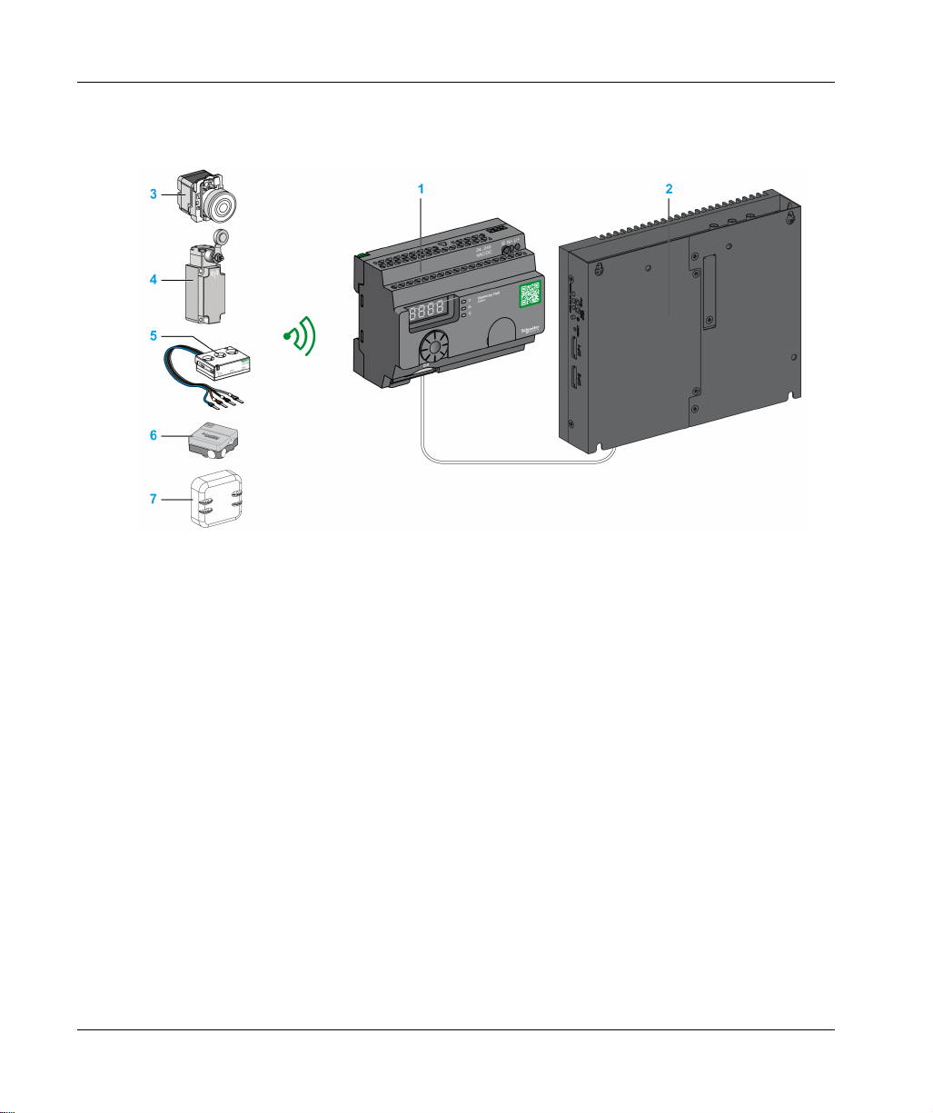
Basic Architecture with PLC
The following figure shows the transmission between transmitters and a ZBRN1 Harmony Hub:
1 Harmony Hub
2 PLC
3 Pushbutton
4 Limit switch
5 Energy sensor
6 Humidity and thermal sensor
7 Thermal sensor
Introduction
NOTE: You can associate 1 Harmony Hub with up to 60 transmitters. Each transmitter has a
unique ID (for example, 030079B1).
PowerTag energy monitoring sensor must be placed in a metal cabinet at a maximum distance of
3 meters to Harmony Hub.
IT/OT Architecture
Harmony Hub provides network connectivity openness by operating as intermediate equipment
between the wireless devices and PLCs (Programmable Logic Controller) or all industrial PCs
(IT/OT box) that support Modbus TCP protocols.
Harmony Hub is providing an easy way to digitalize your production line to improve operation
efficiency by using a non-intrusive wireless system easy to connect to your IT system.
Harmony Hub collect physical signals from an operator interface or secondary sensing to generate
computed data information for computerized maintenance management system (CMMS) tools and
operation management tools.
EIO0000001177 01/2020 15
Introduction
Data can be analyzed through our dedicated EcoStruxure platform through AVEVA™ Software,
Maintenace Advisor software, and Augmented Operator Advisor application.
1 ZBRN1 Harmony Hub associated with ZBRCETH communication module
2 iPC
3 Pushbutton
4 Limit switch
5 Energy sensor
6 Humidity and thermal sensor
7 Thermal sensor
Compatible Transmitters
Harmony Hub is compatible with:
The Harmony batteryless and wireless push-buttons offer based on radio technology (ZBRT1,
ZBRT2)
The Harmony wireless and batteryless rope pull switch (ZBRP1)
The OsiSense wireless and batteryless radio limit switches (XCKW, XCMX)
Temperature sensors with battery (A9XST114, …)
Energy sensors (A9MEM1560, LV434020, …)
The following figures show some examples of transmitters:
16
EIO0000001177 01/2020

Example 1: Push-button with a plastic head
Example 2: Push-button with a metal head
Example 3: Push-button with a plastic head enclosed in a handy box
Introduction
EIO0000001177 01/2020 17

Introduction
Call To Action
Overview
Harmony Hub can communicate with up to 60 ZBRRH receivers.
If you connect a tower light to the ZBRRH receiver, you can make a call to action function.
Call to action:
When a problem occurs on the machine, the operator just pushes its wireless pushbutton.
The Harmony Hub can then control a device to solve the problem or at least to display it with a
tower light.
The following figure shows the transmission between a ZBRN• Harmony Hub and ZBRRH receiver
to command, for example, a tower light:
18
1 Harmony Hub
2 ZBRRH receiver
3 Pushbutton
4 Limit switch
5 Energy sensor
6 Humidity and thermal sensor
EIO0000001177 01/2020
7 Thermal sensor
8 XVU tower light
Call to action process:
Step Action
A If a problem occurs on the machine, the operator pushes its wireless pushbutton.
A message is sent to the Harmony Hub.
B The Harmony Hub send a message to the Maintenance Advisor.
C The Maintenance Advisor send a message to the Harmony Hub.
D The Harmony Hub send a message to a ZBRRH receiver.
E The ZBRRH receiver commands one lamp of the XVU tower light.
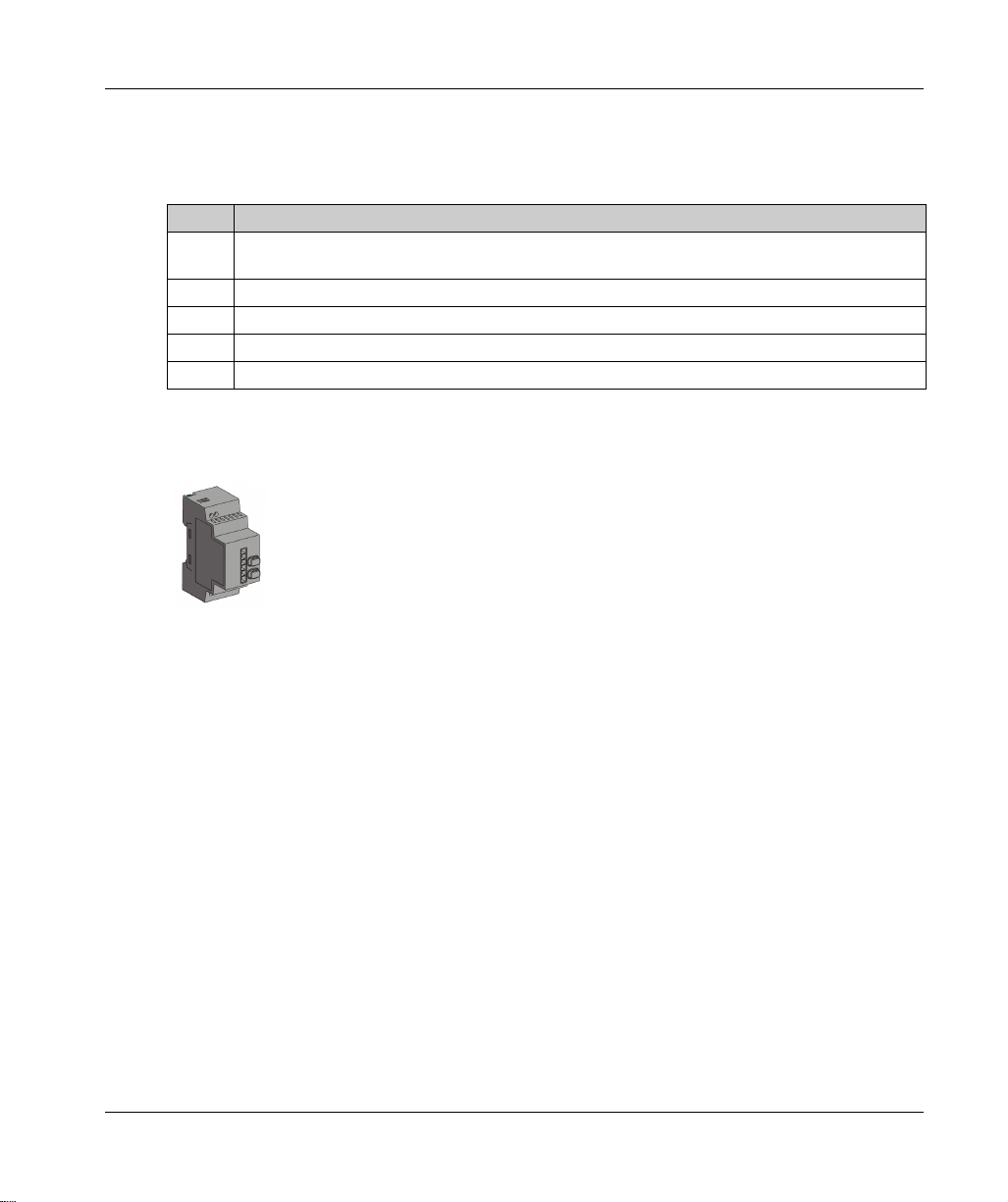
Compatible Receiver
Harmony Hub is compatible with the Harmony ZBRRH receiver:
Introduction
EIO0000001177 01/2020 19
Introduction
Product References
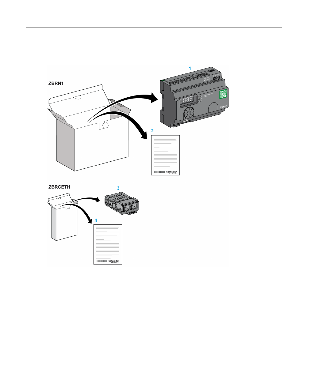
ZBRN1: Standard Harmony Hub with Communication Module
20
1 Harmony Hub
2 Instruction Sheet (ZBRN1)
3 Modbus TCP Communication module
4 Instruction Sheet (ZBRCETH)
NOTE: ZBRN1 must be associated with a communication module, reference ZBRCETH (Ethernet
protocol).
EIO0000001177 01/2020
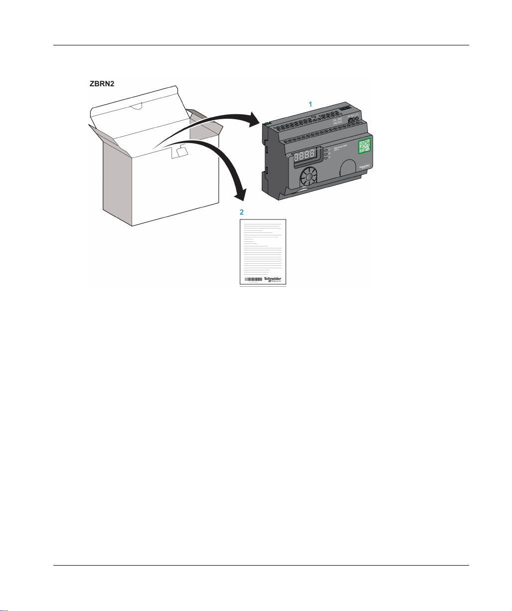
ZBRN2: Harmony Hub for Modbus Serial Line Communication
1 Harmony Hub
2 Instruction Sheet
Introduction
Difference Between ZBRN1 and ZBRN2
ZBRN2 has an embedded communication port for a Modbus serial line, whereas ZBRN1 can
support Modbus TCP communication using ZBRCETH module.
EIO0000001177 01/2020 21

Introduction
22
EIO0000001177 01/2020

Harmony Hub
Physical Description
EIO0000001177 01/2020
Physical Description
Chapter 2
Physical Description
Purpose
This chapter provides an overview of Harmony Hub ZBRN1 and ZBRN2 hardware: description,
output connectors, installation, and power supply connections.
What Is in This Chapter?
This chapter contains the following sections:
Section Topic Page
2.1 Product Overview 24
2.2 Installation 26
2.3 Specifications 38
2.4 Data Management 41
EIO0000001177 01/2020 23
Physical Description
Product Overview
Section 2.1
Product Overview
Hardware Description
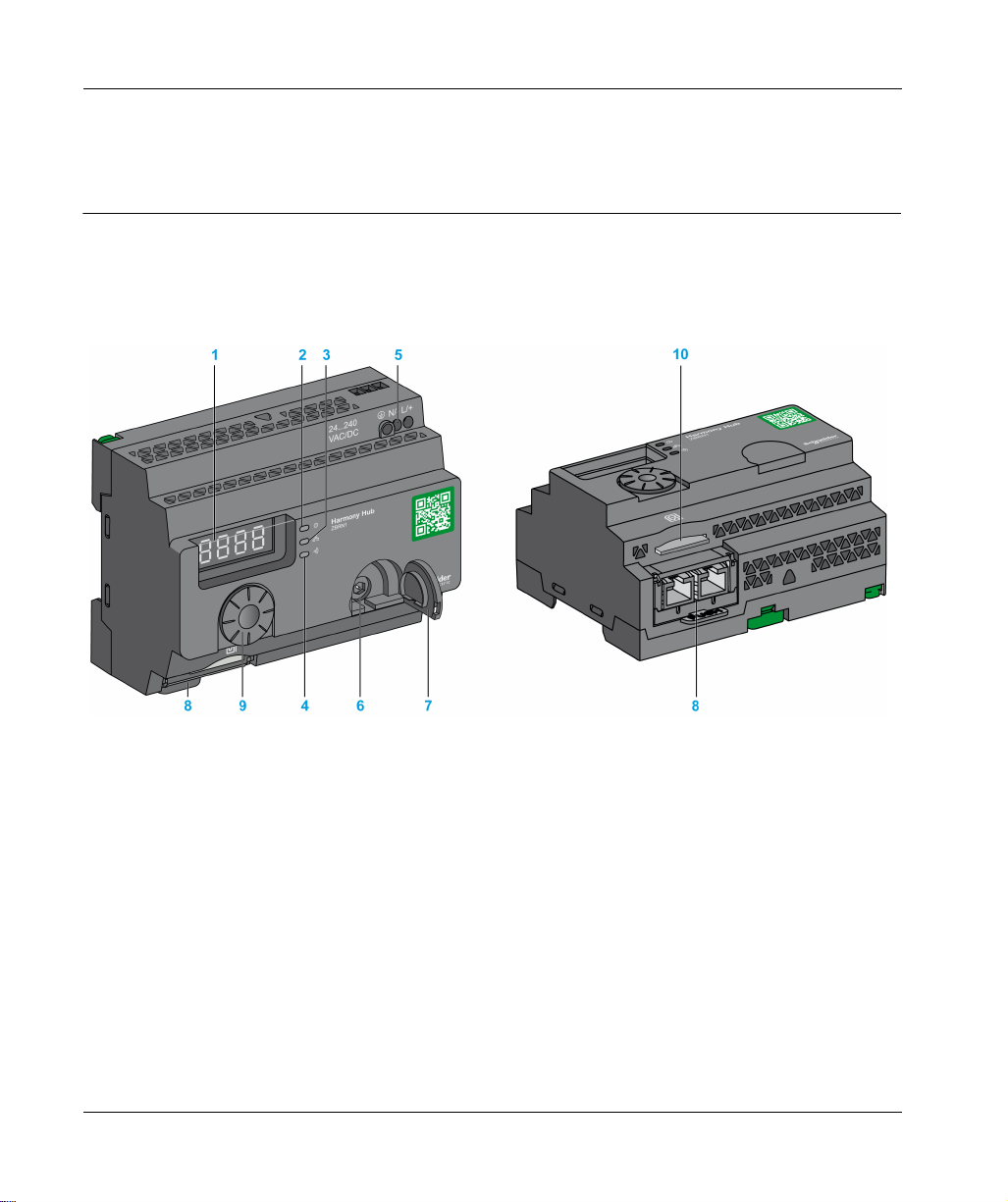
ZBRN1
24
1 Four 7-segments displays with 5 LEDs
2 Power LED
3 Communication LED
4 Radio signal strength LED
5 Power input terminal block
6 Connector for the optional external antenna
7 Protective plug for the connector for the optional external antenna
8 ZBRCETH Communication module inserted with 2 RJ45 Ethernet connectors
9 Jog dial
10 SD memory card slot
EIO0000001177 01/2020
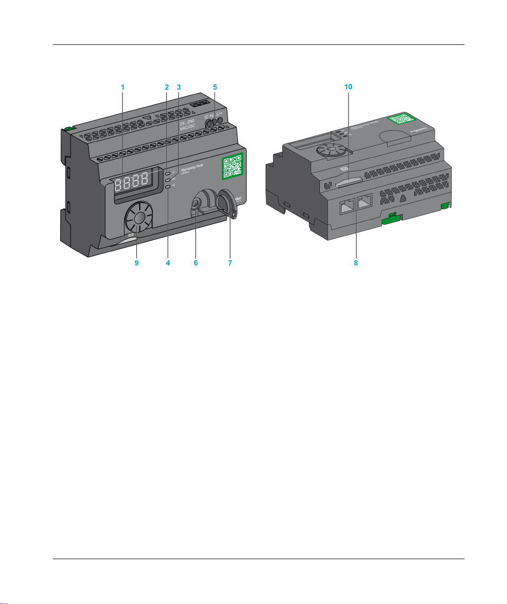
ZBRN2
Physical Description
1 Four 7-segments displays with 5 LEDs
2 Power LED
3 Communication LED
4 Radio signal strength LED
5 Power input terminal block
6 Connector for the optional external antenna
7 Protective plug for the connector for the optional external antenna
8 2 RS-485 Modbus serial line connectors
9 Jog dial
10 SD memory card slot
EIO0000001177 01/2020 25

Physical Description
Installation
Section 2.2
Installation
What Is in This Section?
This section contains the following topics:
Installation Requirements 27
Mechanical Installation 33
Environmental Features 35
Housing 37
Topic Page
26
EIO0000001177 01/2020

Installation Requirements
Before Starting
Read and understand this chapter before beginning the installation of your Harmony Hub.
HAZARD OF ELECTRIC SHOCK, EXPLOSION OR ARC FLASH
Disconnect all power from all equipment including connected devices prior to removing any
covers or doors, or installing or removing any accessories, hardware, cables, or wires except
under the specific conditions specified in the appropriate hardware guide for this equipment.
Always use a properly rated voltage sensing device to confirm the power off where and when
indicated.
Replace and secure all covers, accessories, hardware, cables, and wires and confirm that a
proper ground connection exists before applying power to the equipment.
Use only the specified voltage when operating this equipment and any associated products.
Failure to follow these instructions will result in death or serious injury.
Operating Environment
UNINTENDED EQUIPMENT OPERATION
Install and operate this equipment according to the environmental conditions described in the
operating limits.
Failure to follow these instructions can result in death, serious injury, or equipment damage.
Physical Description
DANGER
WARNING
EIO0000001177 01/2020 27

Physical Description
Installation Considerations
UNINTENDED EQUIPMENT OPERATION
Use appropriate safety interlocks where personnel and/or equipment hazards exist.
Install and operate this equipment in an enclosure appropriately rated for its intended
environment.
Do not use this equipment in safety critical and hoisting machine functions due to:
No permanent communication
No acknowledge of the message from the receiver to the transmitters.
Do not disassemble, repair, or modify this equipment.
Do not connect any wiring to reserved, unused connections, or to connections designated as
not connected (N.C.).
Failure to follow these instructions can result in death, serious injury, or equipment damage.
WARNING
28
EIO0000001177 01/2020
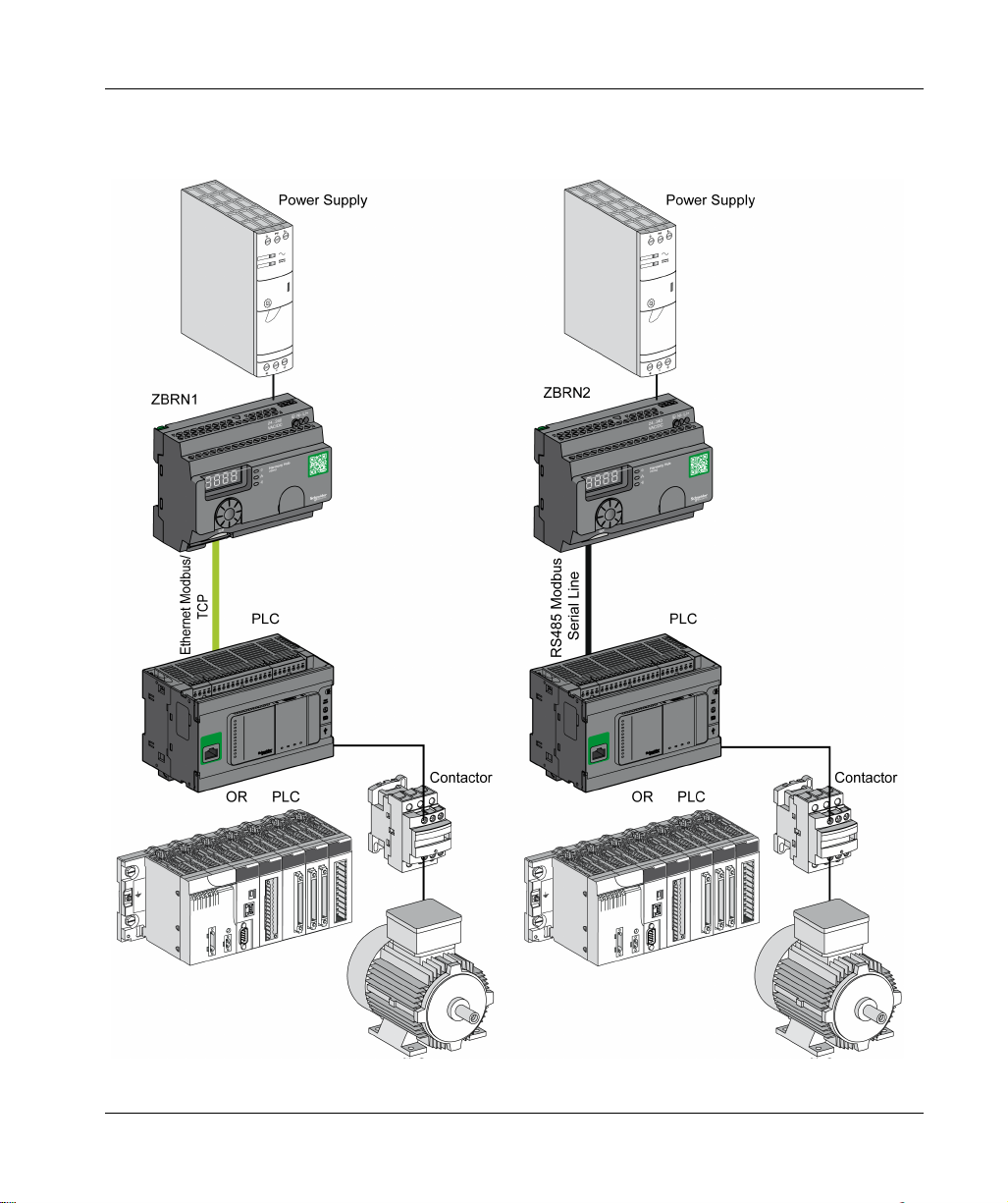
Architecture
The following figures shows the general principle of Harmony Hub architecture:
Physical Description
EIO0000001177 01/2020 29

Physical Description
NOTE:
The previous figure is not exhaustive. It shows only the general principle of the architecture.
Refer to the specifications section
Harmony Hubs.
Refer to the user manual of your associated products for detailed wiring diagrams and
instructions.
Harmony Hub can be connected to any PLC supporting the network buses listed in this
document.
Connection Requirements
Power Supply Connection
24...240 Vac/Vdc
Network connection
RS-485 Modbus serial line network
Ethernet Modbus TCP network
(see page 38)
for detailed wiring diagram and instructions for
30
EIO0000001177 01/2020

Maximum Distances
The following figure shows the maximum distance between the transmitters and the
ZBRN1/ZBRN2 Harmony Hubs:
Physical Description
(*) The application environment can modify the typical values.
(**) Free field (unobstructed and without electromagnetic perturbations).
The level of signal attenuation depends on the material through which the signal passes:
Material Attenuation
Glass window
Plaster wall
Brick wall
Concrete wall
10...20 %
30...45 %
60 %
70...80 %
(*) Values for indication purpose only. Actual values depend on the thickness and nature of the material.
EIO0000001177 01/2020 31
(*)
(*)
(*)
(*)

Physical Description
Material Attenuation
Metal structure
(*) Values for indication purpose only. Actual values depend on the thickness and nature of the material.
NOTE: You can add ZBRA1 or ZBRA2 antenna or both to increase the range.
The reception is reduced if Harmony Hub is placed in a metal cabinet.
For further information on the use of ZBRA1 and ZBRA2 antennas, refer to the Radio chapter
(seepage149)
Impact of the radio performances in the environment:
For any environment, the radio performances are subjected to be instable due to perturbations
made by any kind of industrial machines, processes, or electronic devices.
As a consequence at any time, it is possible that the radio frames sent by a transmitter will not
be caught by the receiver during the perturbation.
With Harmony XB5R offer, only one radio frame is sent to the receiver, there is no permanent
radio communication. This reason prevents the use of Harmony XB5R offer for applications
where permanent reliability and/or permanent precisions are needed.
(*)
60...100 %
.
32
EIO0000001177 01/2020

Mechanical Installation
Mounted on DIN Rail
Harmony Hub must be installed on DIN rails complying with EN/IEC 60715.
To install Harmony Hub, use a tool to press down the D lock for inserting the DIN rail.
The following figure shows the position of Harmony Hub on the DIN rail:
Physical Description
Mounted on a Grid or Plate
Harmony Hub can be installed on a grid or a plate.
The following steps explain how to install the module:
Step Action
1 Pull out the panel mounting hooks.
2 Mount Harmony Hub on the grid or plate using the screws as shown in the
following figure.
EIO0000001177 01/2020 33

Physical Description
34
EIO0000001177 01/2020

Environmental Features
Specifications
The following table shows the general environmental specifications:
Characteristics Specifications
Standards Conformity to
standards
Conformity to
standards
Conformity to
standards
Radio
certifications
Agencies
UL USA UL508, 17th edition
CSA Canada CSA C22.2, No. 142-M2000
C-Tick Australia –
GOST Russia –
ANATEL Brazil –
FCC USA –
SRRC China –
CCC China –
MIC Japan –
RSS Canada –
Ambient operating
temperature
Storage temperature –40...+70 °C (–40...+158 °F)
Relative humidity 95% RH at 55 °C (131 °F)
Degree of pollution 2 (IEC60664-1)
Degree of protection IP20
Shock resistance Half sine wave acceleration: 11 ms 30 gn (IEC 60068-2 27)
Resistance to vibration ±3.5 mm (±0.13 in.): 5...8.14 Hz
Physical Description
R&TTE 1999/5/EC, LVD 2006/95/EC, EMC2004/108/EC
EN/IEC 60947-1, EN/IEC 60947-5-1, EN/IEC60950-1, IEC61131-2, EN
300440-2, EN300489-3, EN300328, EN62311
UL 508 (USA), CSA C22-2 n° 14 (Canada), CCC (China), Gost (Russia)
FCC (USA), CSA, RSS (Canada), C-Tick (Australia), ANATEL (Brazil),
SRRC (China), MIC (Japan)
–25...+55 °C (–13...+131 °F)
1 gn: 8.14...150 Hz when mounted on a panel
2 gn: 8.45...150 Hz when mounted on a DIN rail (IEC 60068-2-6)
EIO0000001177 01/2020 35

Physical Description
Characteristics Specifications
Altitude requirement Operation: 0...2000 m (6561.66 ft)
Storage: 0...3000 m (9842.49 ft)
Only used at altitude not exceeding 2000 m (6561.66 ft).
Only used in non-tropical climate regions.
36
EIO0000001177 01/2020

Housing
Clearances and Mounting Position
(1) To enhance the signal reception, observe the above positioning.
(2) In a metal cabinet, the optimum place for Harmony Hub is on the top. This position avoids obstacles and
enhances the signal reception.
Physical Description
EIO0000001177 01/2020 37

Physical Description
Specifications
Section 2.3
Specifications
Electrical Specifications
Power Supply Specifications
Harmony Hub complies with the following power requirements:
Electrical Features Description
Rated voltage 24...240 Vac 24...240 Vdc
Voltage range 21...264 Vac 21...264 Vdc
Rated frequency 50/60 Hz –
Frequency range 47...63 Hz –
Under voltage protection No
Terminal blocks 3-pin terminal with a pitch of 7.62 mm (0.3 in.) on the output terminal block
Immunity to short interruptions
(Conforming to IEC 61000-4-
11)
Dielectric strength with others 3000 Vac / 4250 Vdc (input-output)
Short-circuit protection Yes (internal fuse 2 A, 250 V)
* PE = protective earth ground
AC Power Supply DC Power Supply
10 ms
1500 Vac / 2150 Vdc (input-PE*)
Power Supply Connections
You can connect the power supply to any common supply from 24...240 Vac/Vdc.
HAZARD OF ELECTRIC SHOCK, EXPLOSION OR ARC FLASH
Comply with the wiring diagram shown immediately after this message.
Failure to follow these instructions will result in death or serious injury.
38
DANGER
EIO0000001177 01/2020

Physical Description
The following table shows the recommended wire sizes for the L/+ and N/- terminals:
The following table shows the recommended wire sizes for the PE terminal (protective earth
ground):
The following table shows the recommend torque for the 3 terminals:
EIO0000001177 01/2020 39

Physical Description
UNINTENDED EQUIPMENT OPERATION
For the protective earth ground (PE) wiring, use a cable not longer than 300 mm (11.8 in.).
Failure to follow these instructions can result in death, serious injury, or equipment damage.
The following table shows the input power consumption:
Reference Input Power
ZBRN1 9 W
ZBRN2 3.3 W
UNINTENDED EQUIPMENT OPERATION
Supply this product with a power line protected by a circuit breaker rated 16 A maximum and
a ground fault circuit breaker.
A readily accessible disconnect device shall be incorporated external to the equipment.
Install this product in an electrical cabinet and lock the cabinet using a key.
Failure to follow these instructions can result in death, serious injury, or equipment damage.
WARNING
WARNING
40
EIO0000001177 01/2020

Data Management
Section 2.4
Data Management
What Is in This Section?
This section contains the following topics:
Compatibility Rules 42
Transmitter Types 43
Monostable Input 45
Set/Reset 46
Receiver Types 47
Physical Description
Topic Page
EIO0000001177 01/2020 41

Physical Description
Compatibility Rules
Transmitter Compatibility
ZBRT2 transmitter is compatible with the following only:
ZBRRA, ZBRRC, and ZBRRD receivers with firmware version 2.0 and higher
ZBRA1 relay antenna with firmware version 2.0 and higher
ZBRN1 /ZBRN2 Harmony Hubs with firmware version higher than 1.2
ZBRN• Harmony Hubs Compatibility
ZBRN• Harmony Hub transmitters are compatible with the following only:
ZBRRH receiver with firmware version 1.03 and higher
42
EIO0000001177 01/2020

Transmitter Types
ZBRT1 and ZBRTP Transmitters
The radio message is sent when the button is pressed, signaled by a click. If the button is held
down, the message is not transmitted continuously. The message is not sent when the button is
released.
To avoid any conflict of multiple transmission from different transmitters, a minimum of 10 ms is
required between each radio transmission.
Physical Description
ZBRT1 is used for applications where single pulse is required (for example, remote start of
machine and reset after machine fault detection).
EIO0000001177 01/2020 43

Physical Description
ZBRT2 Transmitter
The radio message is sent when the button is pressed, signaled by a click.
If the button is held down, the message is not transmitted continuously.
A second radio message is sent when the button is released. This message is not transmitted
continuously. It is transmitted once, at the release of the push-button.
This transmitter is used only for the set/reset output mode.
44
EIO0000001177 01/2020

Monostable Input
Principle
The battery-less transmitter is equipped with a dynamo generator that converts mechanical energy
(produced by pressing the push-button) into electrical energy. A radio-coded message with a
unique ID code is sent in single pulse form.
The radio signal is transmitted when the push-button is pressed. This action is indicated by a click
in the example shown below. If the button is held, the signal is not transmitted continuously. No
signal is sent when the button is released.
The corresponding input channel of Harmony Hub stays active, depending on the input holding
time range, from 100 ms...1 s.
The input holding time is set for all the input channels.
Example
The following figure shows an example of a monostable channel with the input holding time of
500 ms:
Physical Description
EIO0000001177 01/2020 45

Physical Description
Set/Reset
Push-button Set/Reset
NOTE:
1. Release and push again to resynchronize
2. Push and release again to resynchronize
46
EIO0000001177 01/2020

Receiver Types
ZBRN Transmitter / ZBRRH Receiver
Harmony Hub can communicate with up to 60 ZBRRH receivers
Physical Description
EIO0000001177 01/2020 47

Physical Description
48
EIO0000001177 01/2020

Harmony Hub
First Installation
EIO0000001177 01/2020
First Installation
Chapter 3
First Installation
What Is in This Chapter?
This chapter contains the following topics:
First Start Up 50
Configuration 52
Pairing Procedures 54
Topic Page
EIO0000001177 01/2020 49

First Installation
First Start Up
Overview
Follow this procedure when installing and starting up Harmony Hub.
ZBRN1 Startup Procedure
The following table shows the startup procedure for ZBRN1 Harmony Hub:
Step Action Comments
1 Unpack your Harmony Hub (ZBRN1), the
Ethernet communication Module (ZBRCETH),
and check the contents of the packages.
2 Insert the communication module in
Harmony Hub.
3 Choose an appropriate cabinet. Refer to Mechanical Installation
4 Install Harmony Hub on a DIN rail, a grid, or a
plate.
5 If needed, connect the external antenna to
Harmony Hub.
6 Ensure that upstream power is off. Connect the
external 24...240 Vac/Vdc power supply.
7 Turn on the power. –
8 Configure Harmony Hub through the user
interface.
9 Connect Ethernet communication buses and
network.
10 Verify all the connections. –
11 Run the application. –
Refer to package content
Refer to ZBRCETH Communication Module
(see page 62)
.
(see page 20)
.
(see page 33)
Refer to Mounting Tips for ZBRA2 External
Antenna
Refer to Power Supply Connections
(see page 38)
Refer to User Interface
Refer to the Ethernet Cable
.
(see page 151)
.
.
(see page 167)
(see page 71)
.
.
NOTE: If you want to access to call to action features
firmware update (3.29 and higher)
ZBRN2 Startup Procedure
The following table shows the startup procedure for the ZBRN2 Harmony Hub:
Step Action Comments
1 Unpack your Harmony Hub (ZBRN2) and check
the contents of the package.
50
(seepage192)
(see page 18)
.
Refer to package content
, you have to proceed to the
(see page 21)
EIO0000001177 01/2020
.

Step Action Comments
2 Choose an appropriate cabinet. Refer to Mechanical Installation
3 Install Harmony Hub on a DIN rail, a grid, or a
plate.
4 If needed, connect the external antenna to
Harmony Hub.
5 Ensure that upstream power is off. Connect the
external 24...240 Vac/Vdc power supply.
6 Turn on the power. –
7 Configure Harmony Hub through the user
interface.
8 Connect the serial line communication buses and
network.
9 Connect line termination devices to Harmony Hub
(optional).
10 Verify all the connections. –
11 Run the application. –
(see page 33)
Refer to Mounting Tips for the ZBRA2
External Antenna
Refer to Power Supply Connections
(see page 38)
Refer to User Interface
Refer to Modbus Serial Line Cables
(see page 82)
Refer to Modbus Serial Line Cabling
(see page 78)
.
(see page 151)
.
(see page 167)
.
.
First Installation
.
.
NOTE: If you want to access to call to action features
firmware update (3.29 and higher)
EIO0000001177 01/2020 51
(seepage192)
(see page 18)
.
, you have to proceed to the

First Installation
Configuration
Mandatory Settings
Configure the following 2 types of parameters:
Communication protocol
Wireless devices association
Configure Harmony Hubs through the user interface. Refer to Configuration Menu
Transmitters Association Definition
For each input channel of Harmony Hub, the following states are possible:
Empty: No transmitter associated with the input.
Associated off-line: The input parameters are configured but no radio exchanges have been
performed.
Associated on-line: The input parameters are configured and radio exchanges have been
performed.
HMI display for the input states:
I02 means that the input 2 is free
I-02 means that the input 2 is associated off-line
I_02 means that the input 2 is associated on-line
ZigBee Over the Air
The transmitter may be:
Static: Data are only sent by the transmitter to Harmony Hub during pairing.
There is no encryption key or the encryption key is hard-coded in the transmitter and sent to
Harmony Hub.
OTA (Over the Air): The transmitter and Harmony Hub exchange data while pairing.
The encryption key is generated by Harmony Hub and sent to the transmitter.
(see page 167)
.
Supported Transmitter Types
The following transmitter types are supported:
Type
number
1
52
HMI label Related transmitters
So
Push buttons, limit switches, …
EIO0000001177 01/2020

First Installation
Type
number
Pairing Modes
Depending on the type of transmitter associated, three pairing modes are available:
Menu Description Compatible
Id
t
tId
(1) The pairing request must be received by Harmony Hub within 2 minutes after the pairing mode has
been selected.
HMI label Related transmitters
2
3
4
5
6
E3
th
CL
Et
S1
Reserved
Reserved
Humidity and thermal monitoring sensors
Thermal monitoring sensors
Generic ZigBee, PowerTag sensors
Transmitter Types
transmitters
Manual pairing. The ID of the transmitter is
set manually.
Teach pairing
(1)
The first transmitter emitting a pairing
request is paired to this input.
Teach pairing with ID
(1)
Only the transmitter emitting a pairing
request with the correct ID is paired to this
input.
Static transmitters
So
S1
OTA transmitters
So
CL
Et
S1
OTA transmitters
So
CL
Et
S1
Transmitters type
1
6
Transmitters type
1
4
5
6
Transmitters type
1
4
5
6
EIO0000001177 01/2020 53

First Installation
Pairing Procedures
Overview
The steps to follow to add and pair a transmitter to an input of Harmony Hub depends on the type
of transmitter to add.
In the following examples, consider that four inputs are already configured and that the new
transmitter is paired to the free input 2.
Procedure examples:
Adding a Type 1 Transmitter Through the User Interface
Adding a Type 4 Transmitter Through the User Interface
Adding a Type 5 Transmitter Through the User Interface
Adding a Type 6 Transmitter Through the User Interface
Teach an Associated Off-line Transmitter Through the User Interface
Adding a ZBRRH Receiver Through the User Interface
Refer to Supported Transmitter Types
Adding a Type 1 Transmitter Through the User Interface
NOTE: Type 1 transmitters can be paired with several Harmony Hubs.
Steps to follow to add a type 1 transmitter using the Id pairing mode:
Step Action Comment
1 Go on a free input of Harmony Hub (input 2
in this example).
2 Select the type of transmitter. tY.So: push-buttons or limit switches
3 Select the pairing mode. Id: Manual pairing
4 Enter the first two digits of the transmitter ID. -
5 Enter the last two digits of the transmitter ID. I_02 is displayed (associated on-line)
(seepage52)
(see page 54)
(see page 55)
(see page 56)
(see page 57)
(see page 58)
(see page 59)
.
rdY > ConF > In.04 > I02
54
Steps to follow to add a type 1 transmitter using the t pairing mode:
Step Action Comment
1 Go on a free input of Harmony Hub (input 2
in this example).
2 Select the type of transmitter. tY.So: push-buttons or limit switches
3 Select the pairing mode. t: Teach pairing
4 Harmony Hub is waiting for a paring request. t is blinking
rdY > ConF > In.04 > I02
If the commissioning request is not received within
2 minutes I02 is displayed, the input is free.
EIO0000001177 01/2020

Step Action Comment
5 Press the transmitter button 3 times. t1 is displayed at first press
t2 is displayed at second press
t3 is displayed quickly at third press
I_02 is displayed (associated on-line)
Steps to follow to add a type 1 transmitter using the tId pairing mode:
Step Action Comment
1 Go on a free input of Harmony Hub (input 2
in this example).
2 Select the type of transmitter. tY.So: push-buttons or limit switches
3 Select the pairing mode. tId: Teach pairing with ID
4 Enter the first two digits of the transmitter ID. -
5 Enter the last two digits of the transmitter ID. -
6 Harmony Hub is waiting for a paring request. t is blinking
7 Press the transmitter button once. I_02 is displayed (associated on-line)
rdY > ConF > In.04 > I02
If the commissioning request is not received within
2minutes, I-02 is displayed (associated off-
line), refer to Teach an Associated Off-line
Transmitter
(see page 58)
.
First Installation
Adding a Type 4 Transmitter Through the User Interface
NOTE: Type 4 transmitters can be paired with only one Harmony Hub.
The transmitter must be unpaired before to pair it to Harmony Hub.
To unpair the humidity and thermal monitoring sensor, press and maintain the transmitter button
until its embedded led flashes three times, and wait 15 s before to start the new pairing.
Steps to follow to add a type 4 transmitter using the t Id pairing mode:
Step Action Comment
1 Go on a free input of Harmony Hub (input 2
in this example).
2 Select the type of transmitter. tY.CL: Humidity and thermal monitoring
3 Select the pairing mode. tId: Teach pairing with ID
4 Enter the first two digits of the transmitter ID. -
5 Enter the last two digits of the transmitter ID. -
EIO0000001177 01/2020 55
rdY > ConF > In.04 > I02
sensors

First Installation
Step Action Comment
6 Harmony Hub is waiting for a paring request. t is blinking
7 Press and maintain the transmitter button
until its embedded led flashes two times to
set it on commissioning mode
Adding a Type 5 Transmitter Through the User Interface
NOTE: Type 5 transmitters can be paired with only one Harmony Hub. The transmitter must be
unpaired before to pair it to Harmony Hub.
To unpair the thermal monitoring sensor, press and maintain the transmitter button until its
embedded led flashes three times, and wait 15 s before to start the new pairing.
Steps to follow to add a type 5 transmitter using the t Id pairing mode:
Step Action Comment
1 Go on a free input of Harmony Hub (input 2
in this example).
2 Select the type of transmitter. tY.Et: Thermal monitoring sensors
3 Select the pairing mode. tId: Teach pairing with ID
4 Enter the first two digits of the transmitter ID. -
5 Enter the last two digits of the transmitter ID. -
6 Harmony Hub is waiting for a paring request. t is blinking
7 Press and maintain the transmitter button
until its embedded led flashes two times to
set it on commissioning mode
If the commissioning request is not received within
2 minutes, I-02 is displayed (associated off-
line), refer to Teach an Associated Off-line
Transmitter
t1 is displayed at first frame received
t2 is displayed at second frame received
t3 is displayed quickly at third frame received
I_02 is displayed (associated on-line)
rdY > ConF > In.04 > I02
If the commissioning request is not received within
2 minutes, I-02 is displayed (associated off-
line), refer to Teach an Associated Off-line
Transmitter
t1 is displayed at first frame received
t2 is displayed at second frame received
t3 is displayed quickly at third frame received
I_02 is displayed (associated on-line)
(see page 58)
(see page 58)
.
.
56
EIO0000001177 01/2020

Adding a Type 6 Transmitter Through the User Interface
NOTE: Type 6 transmitters can be paired with only one Harmony Hub. A type 6 transmitter must
be unpaired before to pair it to Harmony Hub. For more detailsabout type 6 transmitter unpairing
procedure, refer to the transmitter documentation.
Steps to follow to add a type 6 transmitter using the t Id pairing mode:
Step Action Comment
1 Go on a free input of Harmony Hub (input 2
in this example).
2 Select the type of transmitter. tY.S1: Generic transmitter, PowerTag
3 Select the pairing mode. tId: Teach pairing with ID
4 Enter the first two digits of the transmitter ID. -
5 Enter the last two digits of the transmitter ID. -
6 Harmony Hub is waiting for a paring request. t is blinking
7 The self-powered PowerTag transmitter
sends frame periodically.
First Installation
rdY > ConF > In.04 >I02
If the commissioning request is not received within
2minutes, I-02 is displayed (associated off-
line), refer to Teach an Associated Off-line
Transmitter
t1 is displayed at first frame received
t2 is displayed at second frame received
t3 is displayed quickly at third frame received
I_02 is displayed (associated on-line)
(see page 58)
.
EIO0000001177 01/2020 57

First Installation
Teach an Associated Off-line Transmitter Through the User Interface
A transmitter is associated off-line if the transmitter ID is already configured but no radio exchanges
have been performed.
Steps to follow to teach a transmitter that is associated off-line:
Step Action Comment
1 Go on an associated off-line input of
Harmony Hub (input 2 in this example).
2 Select the pairing mode. t: Teach pairing
3 Harmony Hub is waiting for a paring request. t is blinking
4 According to the transmitter type:
Type 1: Press the transmitter button 3
times.
Type4: Press and maintain the
transmitter button until its embedded led
flashes two times to set it on
commissioning mode.
Type5: Press and maintain the
transmitter button until its embedded led
flashes two times to set it on
commissioning mode.
Type 6: The self-powered PowerTag
transmitter sends frame periodically.
rdY > ConF > In.04 > I-02
If the commissioning request is not received within
2 minutes, I-02 is displayed (associated off-
line).
t1 is displayed at first frame received
t2 is displayed at second frame received
t3 is displayed quickly at third frame received
I_02 is displayed (associated on-line)
58
EIO0000001177 01/2020

Adding a ZBRRH Receiver Through the User Interface
As a prerequisite, the Harmony Hub must have a MAC/ID. For more details, refer to Factory Mode
(seepage182)
.
Steps to follow to teach an Output (ZBRRH receiver) through the user interface:
Step Action Comment
1 On the ZBRRH:
Start Teach mode
2 On the Harmony Hub:
Go on Output configuration menu (input 2 in
this example)
3 Select the pairing mode. t > YES
4 Harmony Hub sends Pairing request -
5 On the ZBRRH:
ZBRRH is commissioned
ZBRRH Receiver turns-on one time (around 1 second) when commissioning and decommissioning with the Harmony Hub.
WARNING
UNINTENDED EQUIPMENT OPERATION
Before performing the ZBRRH commissioning or decommissioning with the Harmony Hub,
consider the effect on all equipment connected to the ZBRRH.
Failure to follow these instructions can result in death, serious injury, or equipment damage.
First Installation
Select button Choice during 3 s.
Then led 1 to 4 blink.
Press button Ok once
rdY > ConF > OU.04 > OU 02
t: Teach pairing
The Q1…Q4 outputs are active during 1 s after the
teaching procedure.
For a graphical explanation, refer to the teach ZBRRH procedure
EIO0000001177 01/2020 59
(see page 93)
.

First Installation
60
EIO0000001177 01/2020

Harmony Hub
Ethernet Communicati on
EIO0000001177 01/2020
ZBRN1 Ethernet Communication
Chapter 4
ZBRN1 Ethernet Communication
What Is in This Chapter?
This chapter contains the following topics:
Communication on The Ethernet Network 62
Addressing Modes 66
Communication and Status Indicator 68
Modbus TCP Settings and Supported Functions 70
Ethernet Cable 71
Topic Page
EIO0000001177 01/2020 61

Ethernet Communication
Communication on The Ethernet Network
Introduction
Ethernet is a widely used, low-cost technology for local area networks. This technology is used to
exchange data between several devices connected together on a network.
Network Connection
1 ZBRN1 Harmony Hub associated with ZBRCETH communication module
2 iPC
3 Pushbutton
4 Limit switch
5 Energy sensor
6 Humidity and thermal sensor
7 Thermal sensor
ZBRCETH Communication Module
ZBRCETH is a communication module that supports Ethernet Modbus TCP protocol.
The following procedure describes the insertion of the communication module:
Step Action
1 Disconnect all power from the ZBRN1 Harmony Hub.
62
EIO0000001177 01/2020

Step Action
2 Place the module in ZBRN1 Harmony Hub.
Ethernet Communication
1 ZBRN1 Harmony Hub
2 ZBRCETH communication module
3 Press firmly into place.
EIO0000001177 01/2020 63

Ethernet Communication
The following procedure describes the removal of the communication module:
Step Action
1 Disconnect all power from the ZBRN1 Harmony Hub.
2 Push down the release tab.
3 Pull out the module.
64
ZBRCETH offers one Ethernet communication port equipped with two RJ45 plugs. It enables daisy
chain wiring between devices without using a switch.
EIO0000001177 01/2020

The following table shows the specifications of the communication module:
Feature Specifications
Plug Two RJ45 connectors
Driver
Type of cable Shielded
Topology Daisy chain
Automatic polarity correction Yes
RJ45 Layout Description
ZBRCETH communication module has two RJ45 connectors for Ethernet connectivity as shown in
the following figure:
Ethernet Communication
10/100 MB/s
Auto negotiation
Half/Full duplex
The following table shows the pin details of the RJ45 connector:
RJ45 pins Signal Description
1 TX+ Transmission signal
2 TX- Transmission signal
3 RX+ Reception signal
4 Unused –
5 Unused –
6 RX- Reception signal
7 Unused –
8 Unused –
EIO0000001177 01/2020 65

Ethernet Communication
Addressing Modes
Address Assignment
Assign the IP address to Harmony Hub using one of the following methods:
By a DHCP (dynamic host control protocol) server.
By a BOOTP (bootstrap protocol) server (BOOTP zone).
Using the IP address stored in the flash memory.
NOTE: If Harmony Hub detects a duplicate address, it does not start until a unique address is
assigned to the transmitter.
Address Assignment by a DHCP Server
The IP address assigned by a DHCP server is stored in a table of DHCP server.
Step Action Comments
1 Select DHCP mode from the Ethernet menu
using the jog dial on Harmony Hub.
2 Select the DHCP value between 0–159 using
the jog dial.
3 Wait 10 s. When the display stops flashing after 10 s,
For further information, refer to the IP setting
menu
(see page 179)
This action defines the device name.
Harmony Hub triggers a request for an IP
address.
.
Address Assignment by BOOTP Server
The BOOTP server contains a MAC address table for the device connected to network with its IP
address. The following steps explain how to assign the address to Harmony Hub from the BOOTP
server:
Step Action Comments
1 Select the BOOTP mode from the Ethernet
menu using the jog dial on Harmony Hub.
2 Wait 10 s. When the display stops flashing after 10 s,
66
For further information, refer to the IP setting
menu
(see page 179)
Harmony Hub triggers a request for an IP
address.
.
EIO0000001177 01/2020

Assignment of Stored IP Addresses
Harmony Hub uses the IP address stored in its flash memory. The following steps explain how to
assign the address to Harmony Hub from the flash memory:
Step Action Comments
1 Select the Static IP mode from the Ethernet
menu using the jog dial on Harmony Hub.
2 Wait 10 s. When the display stops flashing after 10 s,
Modbus Unit ID Parameter
Use the PLC with the following UIDs to access the device communication details:
Use UID 247 to access the Ethernet diagnostics information (ZBRCETH communication
module server).
Use UID to access the Modbus TCP registers, such as input registers and holding time (ZBRN1
Harmony Hub server):
For firmware version ≤ V1.5, use UID 248 or 255 to access the Modbus TCP registers
For firmware version = V3.26, use UID 248 to access the Modbus TCP registers
For firmware version ≥ V3.31, use UID 248 or 255 to access the Modbus TCP registers
Ethernet Communication
Harmony Hub uses the IP address stored in
the flash memory. For further information, refer
to the IP setting menu
Harmony Hub triggers a request for an IP
address.
(see page 179)
.
EIO0000001177 01/2020 67

Ethernet Communication
Communication and Status Indicator
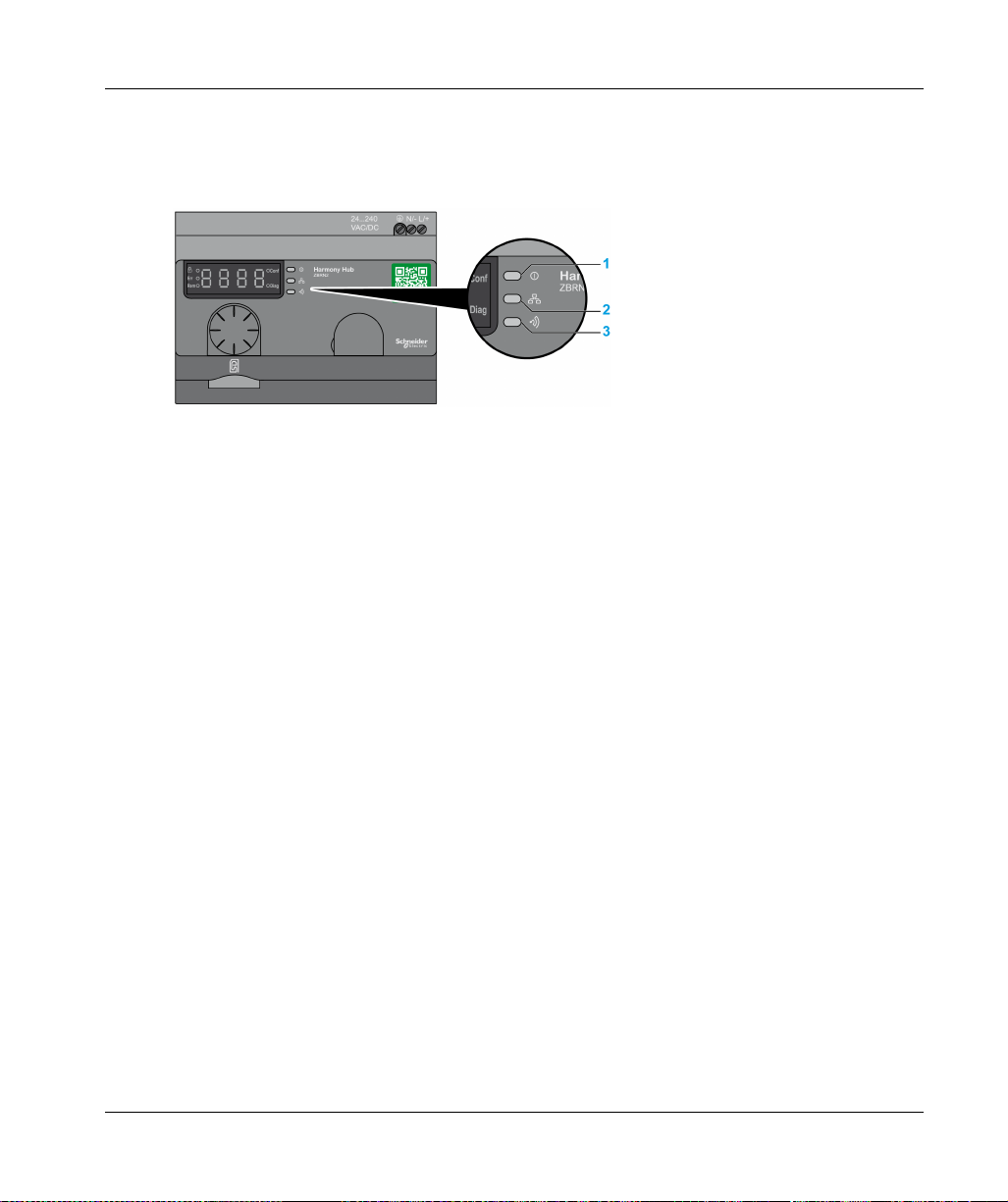
Status LED on The ZBRN1 Harmony Hub
1 Power LED
2 Communication LED
3 Radio signal strength LED
The yellow Ethernet communication LED shows the following status:
On/flashing: Data is being exchanged (depends on the quantity of information).
Off: No data is being exchanged.
Status LED on The ZBRCETH Communication Module
The following table shows the Ethernet Modbus TCP LED status:
Item Name LED State Description Module State
1 Link/Activity port 1 Solid green Ethernet link is present at
100 Mbit/s.
Flashing green Ethernet link is present with
Ethernet traffic at
100 Mbit/s.
Solid yellow Ethernet link is present at
10 Mbit/s.
Flashing yellow Ethernet link is present with
Ethernet traffic at 10 Mbit/s.
68
The module is detecting an
Ethernet link.
The module is detecting Ethernet
traffic.
The module is detecting an
Ethernet link.
The module is detecting Ethernet
traffic.
EIO0000001177 01/2020

Ethernet Communication
Item Name LED State Description Module State
2 Module status Green On. The module is turned on.
Off. The module is off.
3 Network status Red Harmony Hub is being
The module is being turned on.
turned on.
Solid green The network is operating
The module is operating normally.
normally.
4 flashes A duplicate IP condition
The module is offline.
exists.
5 flashes The module is attempting to
get an IP configuration from
BootP server.
6 flashes The operation is normal with
default IP addressing
settings.
4 Link/Activity port 2 Solid green Ethernet link is present at
100 Mbit/s.
Flashing green Ethernet link is present with
Ethernet traffic at
The module is sending
BOOTP/DHCP requests to a
BootP server and awaiting a reply.
The BootP request timed out. The
module applies the default IP
address (85.16.x.y).
The module is detecting an
Ethernet link.
The module is detecting Ethernet
traffic.
100 Mbit/s.
Solid yellow Ethernet link is present at
10 Mbit/s.
Flashing yellow Ethernet link is present with
Ethernet traffic at 10 Mbit/s.
The module is detecting an
Ethernet link.
The module is detecting Ethernet
traffic.
EIO0000001177 01/2020 69

Ethernet Communication
Modbus TCP Settings and Supported Functions
For further information on Modbus TCP settings, refer to the Modbus Settings and Supported
Functions
(seepage80)
.
70
EIO0000001177 01/2020

Ethernet Cable
Ethernet Cable for ZBRN1 Harmony Hub
The following figure shows the Ethernet cable used to connect to the terminal equipment:
Item Description Reference Length
1 Ethernet cable (2 x RJ45
connectors, one at each
end)
Ethernet Communication
490NTW00002U 2 m (6.6 ft)
490NTW00005U 5 m (16.4 ft)
490NTW00012U 12 m (39.4 ft)
EIO0000001177 01/2020 71

Ethernet Communication
72
EIO0000001177 01/2020

Harmony Hub
Modbus Serial Line Communication
EIO0000001177 01/2020
ZBRN2 Modbus Serial Line Communication
Chapter 5
ZBRN2 Modbus Serial Line Communication
Purpose
This chapter provides an overview of the Modbus layout description, communication and status
indicator, line termination mode, settings, and the supported functions.
For more details, refer to Modbus Serial Modbus Serial Link for Machines documentation
(seepage10)
What Is in This Chapter?
This chapter contains the following topics:
Communication on The Modbus Network 74
Communication and Status Indicator 77
Modbus Serial Line Wiring 78
Modbus Settings and Supported Functions 80
Modbus Serial Line Cables 82
.
Topic Page
EIO0000001177 01/2020 73

Modbus Serial Line Communication
Communication on The Modbus Network
Introduction
The Modbus protocol is a master/slave protocol. It allows a single master to request responses
from the slaves, or to act based on the request. The master can address individual slaves, or can
send a broadcast message to all slaves. The slaves return a message (response) to requests
addressed to them individually. The slaves do not return responses to broadcast requests from the
master.
UNINTENDED EQUIPMENT OPERATION
Do not use more than one master on the Modbus network. Unintended I/O behavior can result if
more than one master is able to communicate on the network at the same time.
Failure to follow these instructions can result in death, serious injury, or equipment damage.
Network Connection
WARNING
74
1 PLC as master
2 Modbus Advantys OTB network interface module
3 ZBRN2 Harmony Hub
4 ATV12 drive
5 Modbus serial line
EIO0000001177 01/2020

Modbus Serial Ports
The following figure shows the serial line connectors in ZBRN2 :
1 Serial line connectors
ZBRN2 offers 1 Modbus serial line communication port equipped with 2 RJ45 plugs. It enables
wiring between the devices without using a hub.
The following table shows the specifications of ZBRN2 :
Features Specification
Function Modbus slave and Modbus RTU
Plug 2 RJ45 connectors
Isolated Yes
Maximum cable length 1000 m (3280.83 ft)
Polarization No
Supported baud rates Auto/1200/2400/4800/19200/38400/115200
Parity Even/Odd/No/Auto
Stop bit 1 bit (even and odd)
Modbus Serial Line Communication
2 bits (no parity)
EIO0000001177 01/2020 75

Modbus Serial Line Communication
RJ45 Layout Description
Modbus serial port is an RS-485, 2-wire and common Modbus serial line using a RJ45 connector.
The following figure shows the layout of RJ45 connector:
RJ45 pin Signal Description
1 Unused –
2 Unused –
3 Unused –
4 D1 Transmission signal.
5 D0 Reception signal.
6 Unused Reserved.
7 Unused Reserved (5...24 Vdc).
8 Common Common of signal and supply.
76
EIO0000001177 01/2020
Communication and Status Indicator
Modbus Communication and Status LED
1 Power LED
2 Communication LED
3 Radio signal strength LED
The yellow Modbus communication LED shows the following status:
On/flashing: Data is being exchanged (depends on the quantity of information).
Off: No data is being exchanged.
Modbus Serial Line Communication
EIO0000001177 01/2020 77

Modbus Serial Line Communication
Modbus Serial Line Wiring
Network Connection
You can directly connect Harmony Hub to a PLC for a distance up to 20 m (65.62 ft) as shown in
the following figure:
UNINTENDED EQUIPMENT OPERATION
Use a Modbus serial line cable not longer than 20 m (65.62 ft).
Add a 120 ohm termination line when Harmony Hub is located at the end of the Modbus serial
line (reference VW3A8306RC).
Failure to follow these instructions can result in death, serious injury, or equipment damage.
WARNING
78
EIO0000001177 01/2020
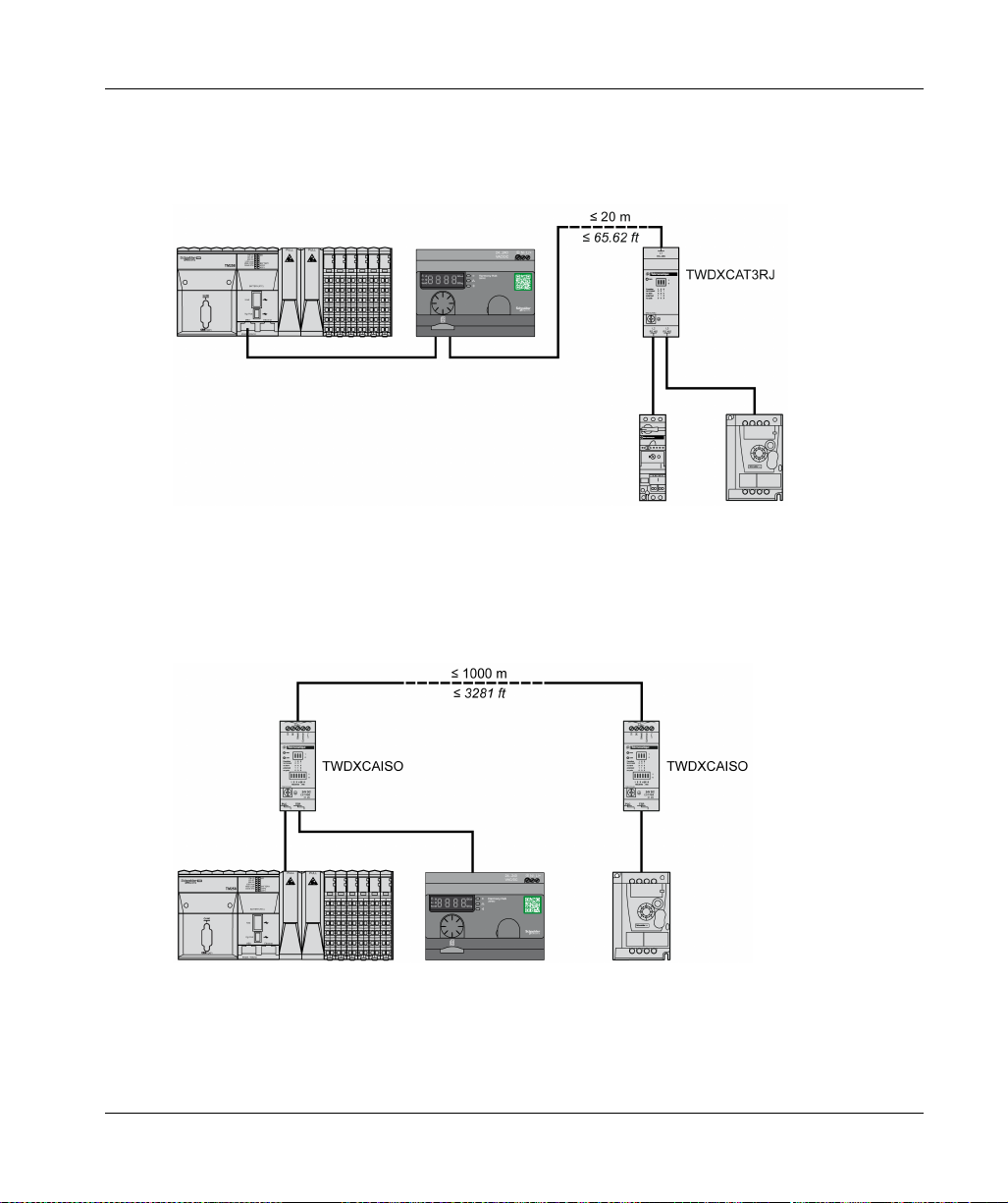
Using TWDXCAT3RJ
TWDXCAT3RJ is used for three connections, polarization, and line termination.
The following figure shows the connection of the device on the bus using TWDXCAT3RJ:
Using TWDXCAISO
TWDXCAISO is used for isolation and line termination.
The following figure shows the connection of the device on the bus using TWDXCAISO
(even if Harmony Hub is already isolated):
Modbus Serial Line Communication
For distances longer than 20 m (65.62 ft), verify that the other devices connected to the bus are
isolated. If other devices are not isolated, use the TWDXCAISO module.
EIO0000001177 01/2020 79

Modbus Serial Line Communication
Modbus Settings and Supported Functions
Modbus Message Structure
The Modbus protocol uses 16-bit words (registers) divided into 2 bytes of 8 bits each.
A Modbus message starts with a header followed by a 1-byte address. A Modbus message uses
a Modbus function as its first byte.
The following table shows the full structure of a Modbus RTU message:
Address Modbus Messages CRC
Function Code Data
1 byte 1 byte n-byte field 2 bytes
List of Supported Commands
The following table shows the list of Modbus commands:
Modbus Function
Code:
Dec Index (Hex)
01 (0001 H) – Read coils. This function code is used to read the
03 (0003 H) – Read holding registers. This function code is used to read the
06 (0006 H) – Write single register. This function code is used to write the
16 (0010 H) – Write n registers. This function code is used to write the
43 (002B H) 14 (000E H) Read device identification. This function code is used to read the
Sub-Function:
Modbus
Encapsulated
Interface
Command Description
content of one or more contiguous coil
statuses in a slave.
content of one or more adjacent
registers in a slave.
content of a register in a slave.
content of one or more contiguous
registers in the slave.
identification and other information
relating to the physical description of a
slave.
NOTE: Registers can be read or written only if the registers are adjacent.
80
EIO0000001177 01/2020

List of Identification Registers
The following table lists the Modbus identification registers:
Identifier Register Name Value Data Type
0 (0000 H)
1 (0001 H)
2 (0002 H)
3 (0003 H)
4 (0004 H)
5 (0005 H)
VendorName
ProductCode
MajorMinorRevision
VendorUrl
ProductName
ModelName
Abort Code
Function Code Abort Code Description
03 H 02 H One of the registers does not exist.
03 H Incorrect register number.
04 H Unavailable value.
06 H 02 H The register does not exist.
04 H Invalid value or register in read only.
10 H 02 H The register does not exist.
03 H Incorrect register number.
04 H Invalid value or register in read only.
2B H 01 H Modbus encapsulated interface different from 14.
02 H Identifier does not exist.
03 H Identifier > 4 or = 0
Modbus Serial Line Communication
Schneider Electric ASCII string
ZBRN1: 052848
ZBRN2: 052849
1.0 for the first official version
https://www.schneider-electric.com
Harmony
ZBRN1
ZBRN2
EIO0000001177 01/2020 81

Modbus Serial Line Communication
Modbus Serial Line Cables
Modbus Serial Line Cables for ZBRN2 Harmony Hub
The following figure shows the Modbus serial line cable with 2 RJ45 connectors to connect to any
device supporting the protocol:
Item Description Reference Length
1 Modbus serial line cable VW3A8306R03 0.3 m (0.9 ft)
VW3A8306R10 1 m (3.2 ft)
VW3A8306R30 3 m (9.8 ft)
82
The following figure shows the Modbus serial line cable with 1 RJ45 connector and 1 mini DIN
connector to connect to a Twido PLC:
EIO0000001177 01/2020

Modbus Serial Line Communication
Item Description Reference Length
2 Modbus serial line cable for Twido PLC TWDXCARJ003 0.3 m (0.9 ft)
TWDXCARJ010 1 m (3.2 ft)
TWDXCARJ030 3 m (9.8 ft)
The following figure shows the Modbus serial line cable with 1 RJ45 connector and one USB
connector to connect to a PC:
Item Description Reference Length
3 Modbus serial line cable TCSMCNAM3M002P 2.5 m (8.2 ft)
The following figures show USB to RS-485 converter and Modbus serial line cable to connect to a
PC:
EIO0000001177 01/2020 83

Modbus Serial Line Communication
Item Description Reference Length
4a USB to RS-485 converter TSXCUSB485 –
4b Modbus serial line cable VW3A8306R03 –
The following figures show USB to RS-485 converter and Modbus serial line cable to connect to a
Twido PLC.
Item Description Reference Length
5a USB to RS-485 converter TSXCUSB485 –
5b Modbus serial line cable for Twido PLC TWDXCARJP03P –
84
EIO0000001177 01/2020

Harmony Hub
ZBRRH Receiver for Harmony Hub
EIO0000001177 01/2020
ZBRRH Receiver for Harmony Hub
Chapter 6
ZBRRH Receiver for Harmony Hub
Purpose
This chapter provides an overview of the Harmony ZBRRH receiver, hardware description, output
connectors, installation, power supply connections, and main procedures.
What Is in This Chapter?
This chapter contains the following topics:
Presentation of ZBRRH 86
General Installation Instruction for ZBRRH 87
Receiver Wiring Diagram 91
LED Status 92
How to Teach/Unteach ZBRRH 93
Lock/Unlock for ZBRRH 96
Total Reset Function Description 99
Topic Page
EIO0000001177 01/2020 85

ZBRRH Receiver for Harmony Hub
Presentation of ZBRRH
Programmable Receiver
The following figure shows the Harmony ZBRRH receiver:
(1): Selection button
(2): Validation button
The following table describes the characteristics of the receiver:
86
Designation Ouputs Receiver Voltage Reference Mass
Receiver with indicator light
LED and teach button
4PNP
200 mA
24 Vdc ZBRRH 0.130 kg
(0.287 lb)
EIO0000001177 01/2020

General Installation Instruction for ZBRRH
Overview
The general installation instructions for ZBRRH are the same as the ZBRN ones:
Maximum distances transmitter/receiver,
The installation conditions,
The mounting tips,
The mounting tips for antenna,
…
For more details, refer to the ZBRRH Instruction Sheet.
Maximum Distances
ZBRRH Receiver for Harmony Hub
(*) Typical values that may be modified by the application environment.
(**) Free field (unobstructed).
NOTE:
The range may be increased by adding antenna ZBRA1.
The range is reduced if the transmitter is placed in a metal box (reduction factor: approx. 10%).
Once wiring is complete, test the product in all possible active areas (while remaining within
range).
NOTE: The relay antenna must have a firmware version ≥V3.2.
EIO0000001177 01/2020 87

ZBRRH Receiver for Harmony Hub
The level of signal attenuation depends on the materials through which the signal will pass:
Material Attenuation
Glass window 10...20 % (*)
Plaster wall 30...45 % (*)
Brick wall 60 % (*)
Concrete wall 70...80 % (*)
Metal structure 60...100 % (*)
(*) Values for indication purposes only. Actual values depend on the thickness and nature of the material.
Installation Conditions
Receiver operating temperature -25...+55°C (-13...+131°F)
Receiver protection level IP20
88
EIO0000001177 01/2020

Mounting Tips for Antenna
The ZBRA1 relay antenna is installed with regard to its vertical axis as shown in the following figure
The antenna and the receiver are installed following their vertical axis.
The relay antenna is used to bypass the obstacle as shown in the following figure:
ZBRRH Receiver for Harmony Hub
EIO0000001177 01/2020 89

ZBRRH Receiver for Harmony Hub
NOTE: The antenna should be placed before the obstacle. The signal will be amplified before the
obstacle to enable to go through it.
Impact of the radio performances in the environment:
For any environment, the radio performances are subjected to be instable due to perturbations
made by any kind of industrial machines, processes, or electronic devices.
As a result at any time, it is possible that radio frames sent by a transmitter will not be caught
by the receiver during the perturbation.
With XB5R offer, only one radio frame is sent to the receiver and there is no permanent radio
communication. This reason makes to avoid the use of XB5R offer for applications where
permanent reliability and/or permanent precisions are needed.
90
EIO0000001177 01/2020
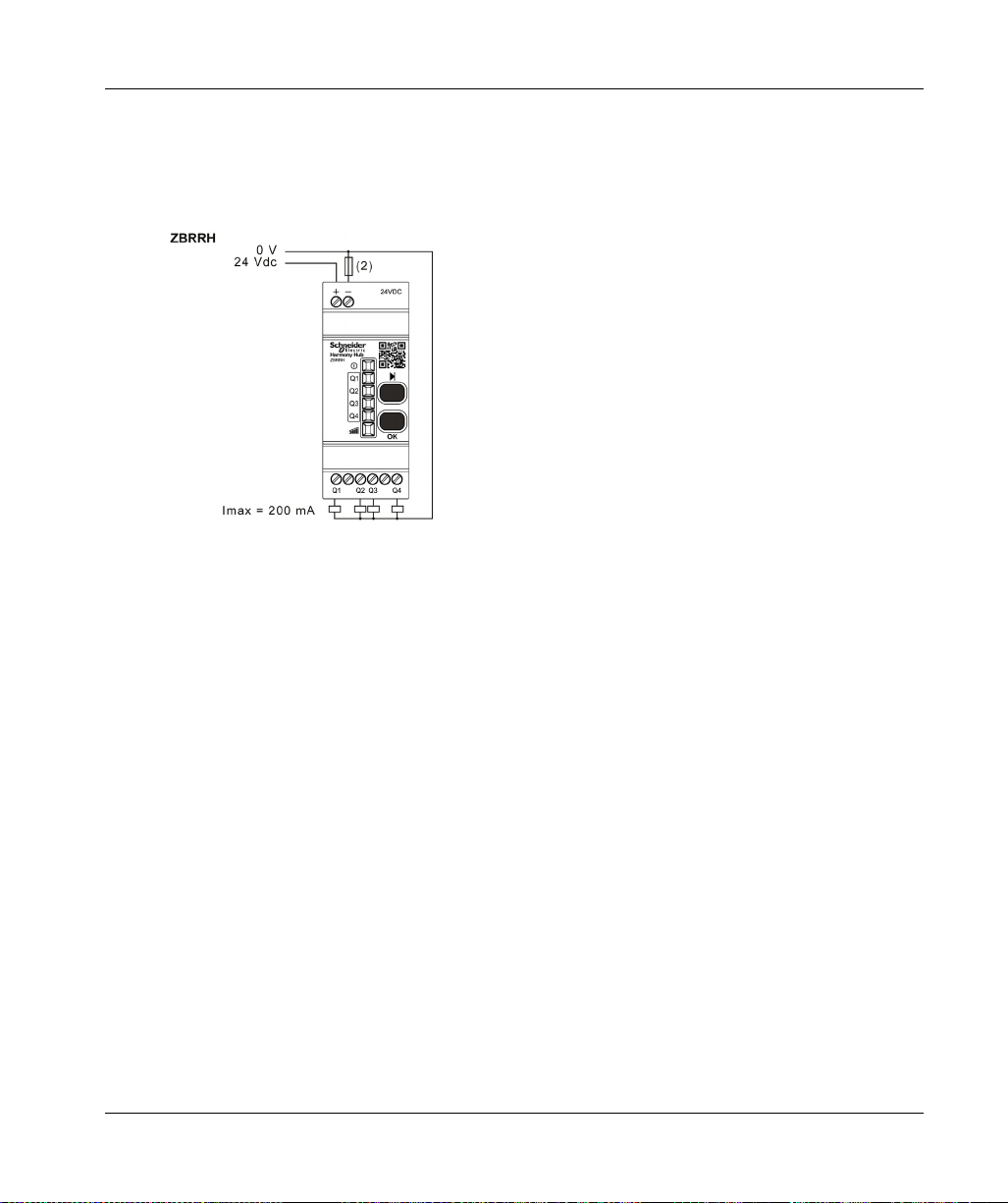
Receiver Wiring Diagram
Wiring Diagram
The following figure shows the wiring diagram for the Harmony ZBRRH receiver:
(2): 500 mA fuse from supplier Bussman® reference GMA-500 mA, 250 V 0.5 A fast-blow.
ZBRRH Receiver for Harmony Hub
EIO0000001177 01/2020 91

ZBRRH Receiver for Harmony Hub
LED Status
ZBRRH
92
EIO0000001177 01/2020

How to Teach/Unteach ZBRRH
Legend
The icons shown have the following meanings:
LEDs Meaning
Green
Yellow
Flashing
Teach ZBRRH Procedure
As a prerequisite, the Harmony Hub must have a MAC/ID. For more details, refer to Factory Mode
(seepage182)
.
ZBRRH Receiver for Harmony Hub
EIO0000001177 01/2020 93

ZBRRH Receiver for Harmony Hub
This procedure shows how to Teach Q1…Q4 outputs (ZBRRH):
94
NOTE:
If the ZBRRH receive any request from other ZBRN, the teaching procedure can not be
performed.
The Q1…Q4 outputs are active during 1 s after the teaching procedure.
The teaching procedure must be performed within 1 min 30 s.
EIO0000001177 01/2020

Unteach ZBRRH Procedure
This procedure shows how to Unteach Q1…Q4 outputs (ZBRRH):
ZBRRH Receiver for Harmony Hub
NOTE: The Q1…Q4 outputs are active during 1 s after the teaching procedure.
EIO0000001177 01/2020 95

ZBRRH Receiver for Harmony Hub
Lock/Unlock for ZBRRH
Introduction
Lock enables to block the menus access by non authorized persons. The functioning of the
receiver is not affected.
96
EIO0000001177 01/2020

Electronic Lock/Unlock
This procedure shows how to electronically lock/unlock the receiver:
ZBRRH Receiver for Harmony Hub
EIO0000001177 01/2020 97

ZBRRH Receiver for Harmony Hub
Mechanical Lock/Unlock
The following diagram shows how to perform buttons mechanical lock.
98
EIO0000001177 01/2020

Total Reset Function Description
Total Reset procedure for ZBRRH
Total Reset: After a Total Reset, the receiver is on factory setting. The registered ID is canceled.
ZBRRH Receiver for Harmony Hub
EIO0000001177 01/2020 99

ZBRRH Receiver for Harmony Hub
100
EIO0000001177 01/2020
 Loading...