

GENERAL INFORMATION
For proportional temperature control, used with receiver-controllers.
May be used with one or more calibrated gauges for continuous
temperature indication at any local or remote position.
Specifications
Construction: Bimetal element, non-adjustable.
Shipping Ambient Temperature Limits: -40 to 150 F (-40 to
65 C).
Air Connections:
TKS-5001, 5/32" dia. spring reinforced plastic tube.
TKS-6001, barbed fitting for 5/32" plastic tube.
Air Consumption For Sizing Air Compressor:
.024 scfm (11.3 ml/s).
Air Capacity for Sizing Air Mains: 50 scim (13.7 ml/s).
Supply Pressure (Indication Only): 20 psig (138 kPa)
nominal. 18 psig (124 kPa) minimum.
Maximum Safe Supply Pressure: 30 psig (207 kPa).
Mounting Dimensions: Wall: 4-3/8" (111 mm) high x 2-3/4"
(70mm) wide x 1-5/8" (41 mm) deep.
Light Troffer: 3/8" (10 mm) x 3/8" (10 mm) x 3" (76 mm).
Mounting Fittings: Order separately for type of wall
construction.
ACCESSORIES
Part Number Description
20-944 Restrictor tee, copper tubing, 1 SCFH.
21-038 Restrictor tee, polyethylene tubing, 1 SCFH.
21-153 In-line restrictor.
AT-201 Copper bulb well.
AT-203 Stainless steel bulb well.
AT-208 Duct moun ing kit for TKS-40xx.
AT-2 11 Bulb shield for wall mounting TKS-2031.
AT-504 Plaster hole cover (small).
AT-506 Pneumatic wall box fitting (two tubes) used for mtg.
AT-533-101 Adaptor 1/4 in. plastic to 5/32 in. plastic.
AT-533-127 Adaptor 3/16 in. copper or 1/4 in. copper with 1/4 in. solder
AT-533-129 5/32 in. x 5/32 in. barbed brass connector.
TOOL-100-500 Calibration panel
T-532-1
1-1-01 under cover of TKS-5001.
A
coupling (n
ot included) to 5/32 in. plastic.
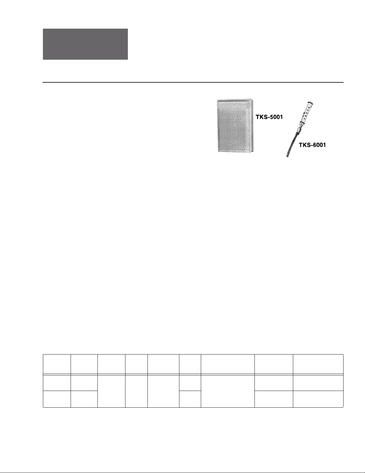
TKS-5001 and TKS-6001
Pneumatic Temperature Transmitters—Room
General Instructions
TKS-5001
Transmitter is shipped with mounting screws and one inch copper
tubes.
Range
on-A
Model No. Mounting
TK
S-5001 Wall
TKS-6001
a
Order fittings separately for type of wall construction.
Light
Troff e
(N
F ( C)
a
50 to 100
(10 to 38)
a
r
Span
dj.)
F ( C)
50 (28) Bimetal
Sensing
Element
Descri
ption
Cover
Beige
Plas
N.A.
Ambient Temperature
tic
Limits
F ( C)
Shipping
0 to 150
-4
(-40 to
65)
Operating:
50 to 100
(10 to 38)
Connections
Air
:
5/32 in. dia. spring
orced pl
tube
tube
astic
astic
reinf
5/32 in. dia. spring
reinforced pl
Dimensions
H x W x D
in. (mm)
4-3/8 x 2-3/4 x 1-5/8
x 4 1 )
(111 x 7 0
3/8 x 3/8 x 3
(10 x 10 x 76)
PRE-INSTALLATION
Check the carton and device for signs of damage.
Printed in U.S.A. 1/10 © Copyright 2010 Schneider Electric All Rights Reserved. F-14241-10


Mounting of TKS-5001 on AT-506 Wall Box Fitting Or
Electrical Switchbox with Restrictor Tee Under The
Cover (Requires AT-532-111-1-01 Kit - See Figure 4)
1. Remove cover.
2. Remove 5/32" tube on TKS-5001 from mounting plate.
Caution: Do not remove the end which is in the tube (connected to
sensing element).
3. Cut the tube and spring 2-1/2" (65 mm) from the tygon tubing.
4. Connect the tube to one side of the restrictor tee.
5. Connect the black tube to the main connection of the restrictor
tee. Insert one spring into the tube. Cut off excess spring. Insert
the black tube
then through the large oblong hole in the back plate.
6. Connect the white tube to the remaining side connection of the
restrictor tee. Inser
excess spring. Insert the white tube through a hole on the right
hand bracket next to the transmitter, and then insert through the
oblong hole in the back plate.
7. Install the insulator card by inserting the black tube through the
t hand hole and the white tube through the ri
lef
8. Insert the black tube into the left hand hole in the wall fitting or
connect to the main line.
9. Insert the white
connect to the transmitter (bran
10. Attach the transmitter back plate to the wall box with screws
provided.
11. Replace cover and tighten cover screw.
through a hole in the left hand side bracket and
t the other spri
tube into the right hand hole in the wall fitting or
ng into the tube and cut o f and
ght hand hole.
ch) output line.
Mounting of TKS-6001 on Light Troffer
Figure-6
Mountin
The transmitter must be located in the return air grille opposite the
fixture exhaust air opening when mounting in recessed combination
light fixture/air diffuser (See Figure 5).
A 1/2" knockout is provided in the corre
for the admittance of the transmitter. Light Fixtures come equipped
with the return air grille assembly attached to the hinged access door
(See Figure 6).
g Location
ct end of the light fi
xture shell
Mounting
Barbed end fitting for 5/32" plastic tubing. Run shortest length of 5/32"
plastic tubing possible from transmitter [no more than 3 ft. (1 m)]
before connecting to 1/4" plastic tubing.
Figure-5 Locating TKS-6001 in Troffer End Opposite
Exhaust Grill.
F-14241-10 © Copyright 2010 Schneider Electric All Rights Reserved. 3

 Loading...