

Page 1
SmartStruxure Lite
Solution
Smart Controllers (SEC-TE, SED-0)
Installation Instructions
Get Control. Get Efficient. Get Value
Page 2

Schneider Electric | II-SSL-SEC-TE-SED-0 -A4.EN.08.2016.v2 August 2016
SmartStruxure Building Peripherals User Guide
About this User Guide
This document contains the user guide for the SmartStruxure™ Lite Wireless Smart
building peripherals.
NOTE: The content of this document is applicable to the features of SmartStruxure
Lite Building Peripherals firmware version 1.4 and subsequent.
Who Should Read this Guide
This guide is for building automation professionals including engineers, contractors,
and electricians.
SmartStruxure Lite Wireless Smart building peripherals are programmable wireless
devices for the building automation industry. This document helps you understand,
install, operate, and maintain your SmartStruxure Lite peripherals.
Related Topics
2
To appreciate the full functionality of SmartStruxure Lite Wireless Building Peripherals,
a prior knowledge of the following topics and products is required:
• SmartStruxure Lite solution Multi-purpose Management Devices (MPM)
• ZigBee
• Lua script
Safety
Installation, operation, and maintenance of SmartStruxure Lite’s Wireless Building
Peripherals may require working with live electrical components. Only qualified
licensed electricians or other individuals who have been properly trained in handling
live electrical components should perform these operations.
Failure to follow electrical safety precautions when exposed to live electrical
components could result in death or serious injury. Always respect local codes and
regulations when installing SmartStruxure Lite products.
Page 3
Schneider Electric | II-SSL-SEC-TE-SED-0 -A4.EN.08.2016.v2 August 2016
Overview
SmartStruxure Lite’s building peripherals are smart wireless devices that address
specific building applications with the added value of wireless communication, along
with local and distributed intelligence.
This document presents the following two SmartStruxure Lite Wireless Building
Peripherals:
• SED-0
• SEC-TE
IMPORTANT NOTE: SmartStruxure Lite Wireless Building Peripherals are NOT
stand-alone solutions. The SED-0 and SEC-TE require a section Manager, such as a
MPM-UN, to function correctly.
SED-0 Smart Wireless Actuator
The SED-0 is a locally programmable valve/damper actuator that communicates
wirelessly with SmartStruxure Lite Managers and gateways.
The SED-0 has an internal ZigBee transceiver and antenna, enabling it to
communicate with SmartStruxure Lite controllers and gateways.
The SED-0 internal memory contains a control engine that supports local scripting
programmability, enabling simple stand-alone control and/or a fail-safe mechanism.
The device has the following object properties:
• Damper setpoint
• Damper position
• 2 universal Inputs
• 1 feedback output signal
• 2 analog value objects
• 1 Lua script
3
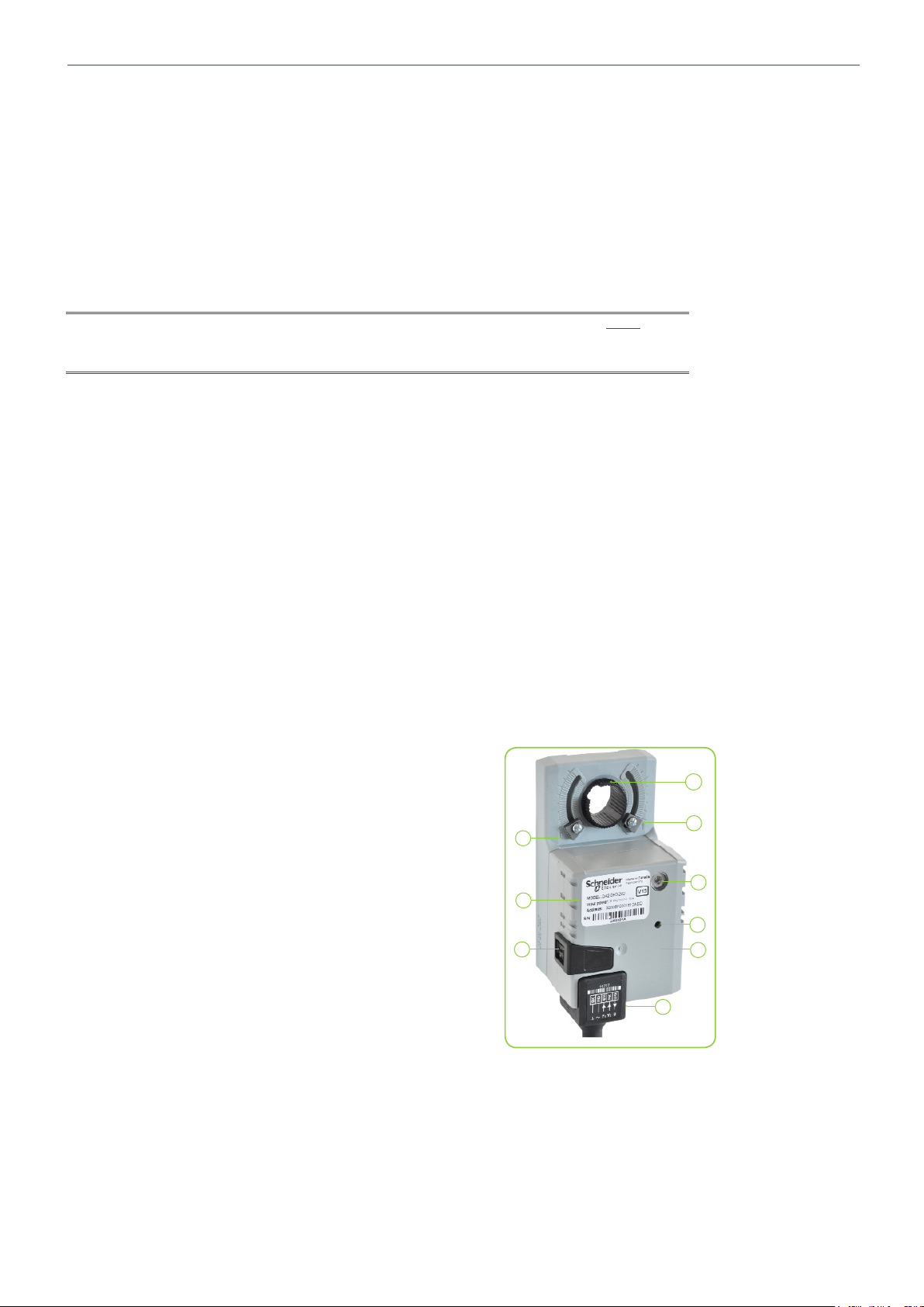
Physical Characteristics and Interactions
The figure shows the physical characteristics of the SED-0.
1. Actuator
2. 100% position of SED-0
3. LED
4. Network scan button
5. SED-0 body
6. Power supply and I/O connector
7. Manual override button
8. Label
9. 0% position of SED-0
1
9
8
7
2
3
4
5
6
Page 4
Schneider Electric | II-SSL-SEC-TE-SED-0 -A4.EN.08.2016.v2 August 2016
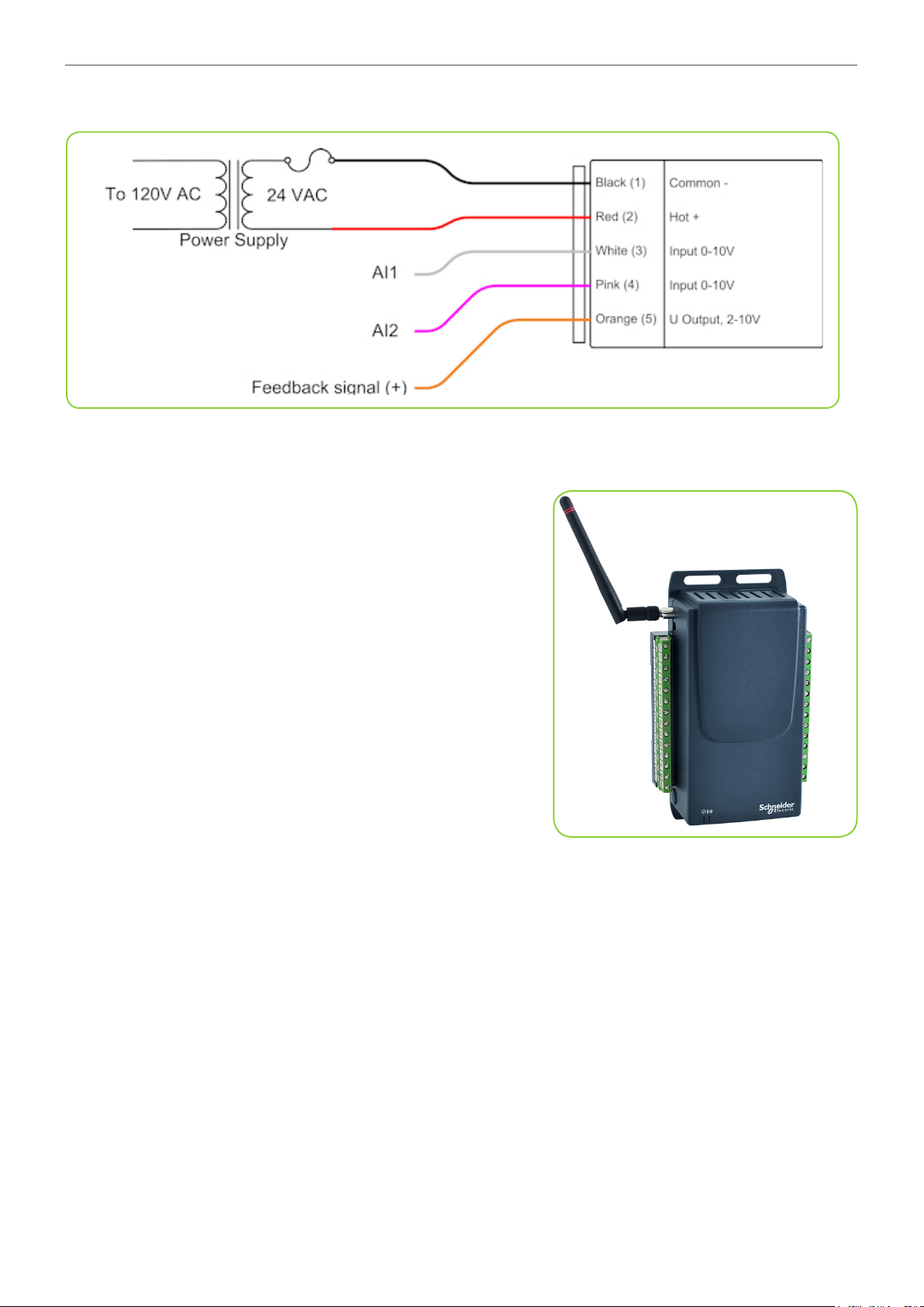
The below figure shows the wiring diagram for the SED-0.
SEC-TE Terminal Equipment Controller
The SEC-TE is a programmable controller for terminal
equipment applications such as fan coil units. The SEC-TE
has an internal ZigBee transceiver and antenna, enabling it to
communicate with SmartStruxure Lite controllers and gateways
and other compliant devices.
The SEC-TE internal memory contains a control engine that
supports local scripting/programmability, which creates a
simple stand-alone control and/or fail-safe mechanism.
The device has the following object properties:
• 4 universal inputs
• 4 analog outputs
• 5 binary outputs (dry contacts)
• 2 analog value objects
• 1 Lua script
The SEC-TE can also be used as a pulse counter with one
analog input configurable for this function.
4
Page 5
Schneider Electric | II-SSL-SEC-TE-SED-0 -A4.EN.08.2016.v2 August 2016
Overview
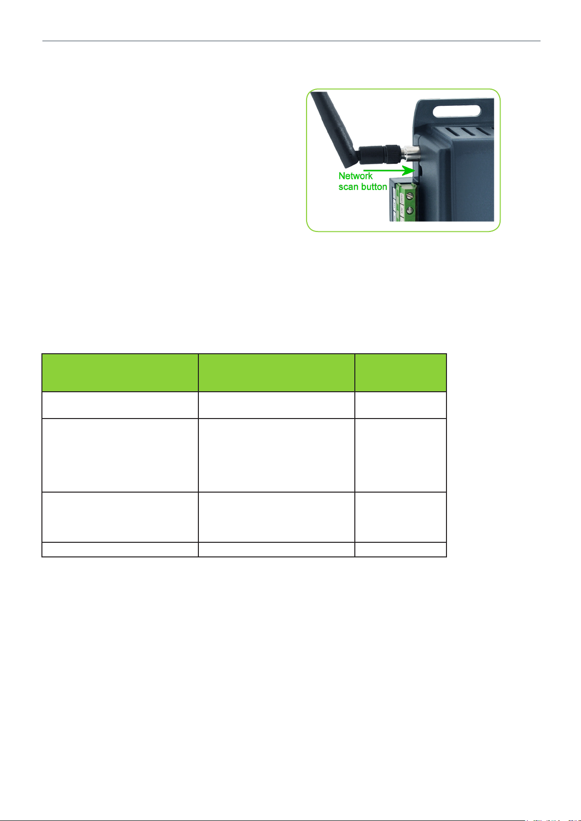
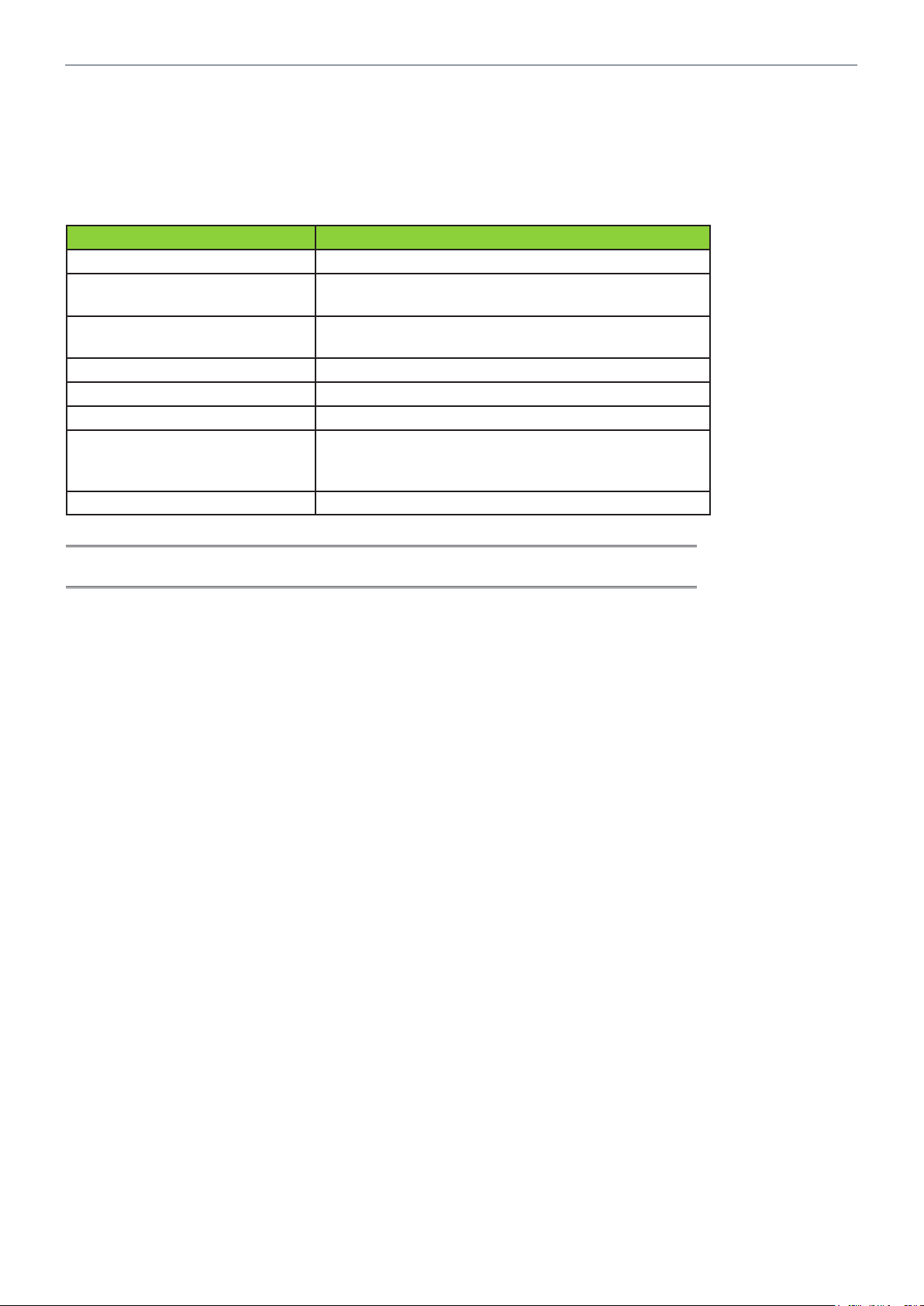
Network Scan Button Detail (all models)
The network scan button is recessed. Operation of the
button requires the use of a small, narrow tool such as
an Allen key.
Network Scan Button Action
Table 1 below shows the effects when pressing and
holding the network scan button on your Building
Peripheral.
5
Table 1
Actions applied to button by
user
Hold down between 1s and 5s Device tries to connect to the
Hold down between 6s and 30s Device scans for joinable
Hold down more than 30s Device clears all analog out-
Hold down less than 1s No action performed LED not affected
Actions performed on release of
button
next network on its list
networks (with user defined
extended pan id if applicable)
and compiles a list of networks
it finds, up to a maximum of 5
networks
puts, binary outputs, analog
values, and Lua script. It also
causes the device to reboot
Corresponding
Blue LED behavior
LED flashes
slowly (400ms)
LED flashes rapidly (200ms)
LED turns OFF
Page 6
Schneider Electric | II-SSL-SEC-TE-SED-0 -A4.EN.08.2016.v2 August 2016
LED Behavior
Each Building Peripheral has a blue LED and a green LED. During operation of the
devices, the green LED remains illuminated solid.
The blue LED behavior characteristics are shown in Table 2 below.
Table 2
Blue LED Behavior Corresponding device behavior
LED ON 200ms every second Device is scanning for joinable Zigbee networks
LED ON 500ms every second Device is trying to join one of the networks it has
found during the scan
LED ON 800ms every second Device is trying to rejoin the network it was connect-
ed to after a loss of connection or a reboot
LED ON Device is connected to a network
LED flashes (400ms) Button is being held down between 1s and 5s
LED flashes (200ms) Button is being held down between 6s and 30s
LED OFF for 1s (pause) This pause in the LED pattern indicates the device
could not connect to a network. The device tries to
connect to the next network on its list.
LED OFF Button is being held for down more than 31s
NOTE: On the SED-0, both LEDs are viewed through the same circular glass. The
dominant color of the LED indicator is blue. You should not see a green LED indicator.
6
Page 7
Schneider Electric | II-SSL-SEC-TE-SED-0 -A4.EN.08.2016.v2 August 2016
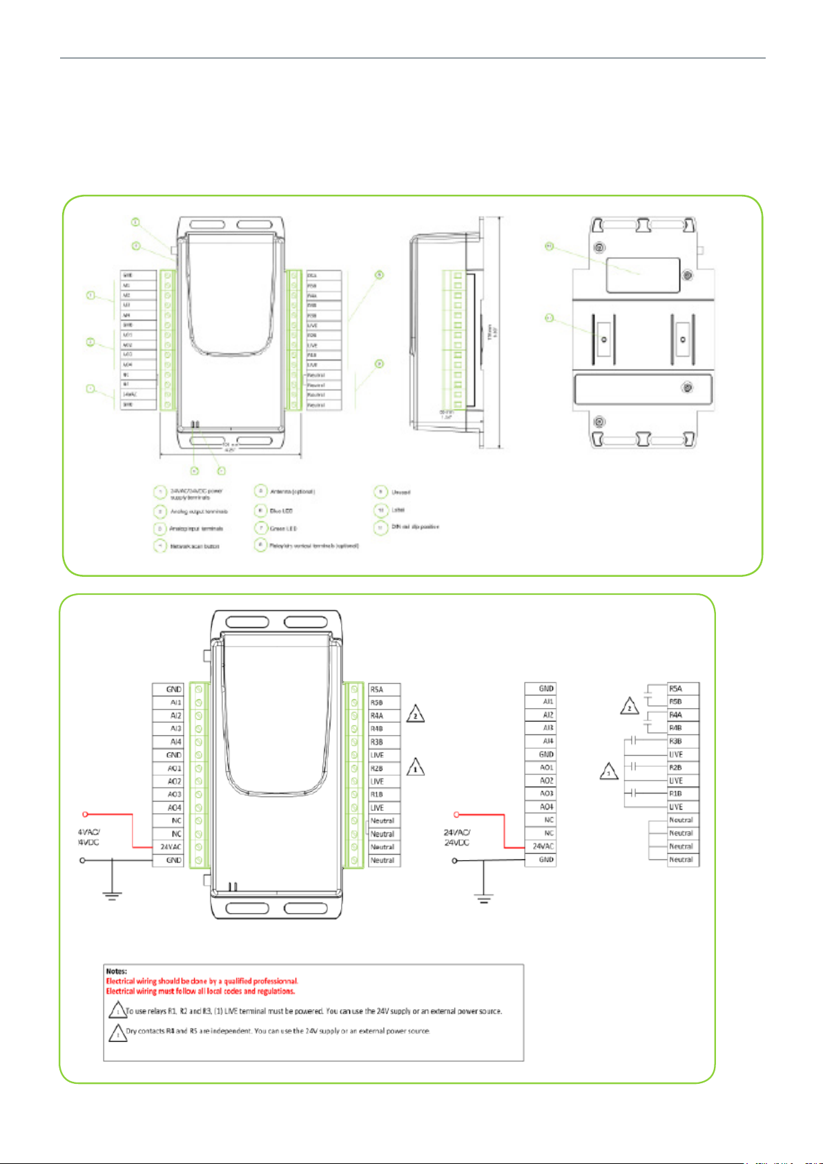
Wiring Diagram
The wiring diagrams for the 24VAC/24VDC SEC-TE smart wireless managers are
shown below.
24VAC/24VDC
7
Page 8

Schneider Electric | II-SSL-SEC-TE-SED-0 -A4.EN.08.2016.v2 August 2016
115VAC/230VDC
The wiring diagrams for the 115VAC/230VAC SEC-TE smart wireless managers are
shown below.
8
Page 9

Schneider Electric | II-SSL-SEC-TE-SED-0 -A4.EN.08.2016.v2 August 2016
Software Interaction
This section presents general operation of SmartStruxure Lite Building Peripherals, as
well as an overview of the different states of a Building Peripheral. This information
should be read in conjunction with the Device Behavior section to gain a full
understanding of the behavior of your Building Peripheral in different stages of
operation.
Scanning for Zigbee Networks
Wireless communication with your Building Peripheral requires the device join a
ZigBee network previously formed by one or more SmartStruxure Lite Managers.
A SmartStruxure Lite Building Peripheral can store in its memory the information
to connect to five different Zigbee networks. Your device discovers the available
networks in its communication range by doing a network scan.
The network scan occurs under one of the following two conditions:
• Automatic scan: when a SmartStruxure Lite Building Peripheral is powered up
and its internal memory contains no network information such as a new Building
Peripheral or device that was never connected to a Zigbee network.
• Manual scan: when the Building Peripheral network scan button is pressed for
more than five seconds and less than 30 seconds to initiate the scan.
If the network scan is unsuccessful and the device cannot find an available Zigbee
network, the device remains disconnected and stays in that state until a manual
network is initiated and a joinable network is found.
9
Joining a Zigbee network
After a successful scan, the Building Peripheral automatically joins the first Zigbee
network stored on its list. When the blue LED on the Building Peripheral stops flashing,
the Building Peripheral has joined a network.
If for some reason it cannot join the first network on the list before reaching a
programmed timeout, the device automatically tries to join the next network. The
device repeats this sequence until it joins a network on its list, or a manual network
scan is initiated to refresh its network list.
Refer to the following two sections for more details:
• “Procedure - Configure Zigbee” on page 10
• “Using Com Log” on page 14
Page 10

Schneider Electric | II-SSL-SEC-TE-SED-0 -A4.EN.08.2016.v2 August 2016
Procedure - Configure Zigbee
NOTE: This procedure assumes you have already wired electrical power to your
device as per the wiring diagrams. For the purpose of this procedure, a SED-0
Building Peripheral is used. The procedure is identical for the SEC-TE except where
otherwise indicated. Also, ensure Devices tab on left side of Building Expert is
expanded before you start the procedure.
Configure ZigBee
10
1. In Devices tab, select your Multi-purpose Manager.
2. In Object tab, select ZigBee Configuration (ZBC1) object.
3. Set following parameters accordingly:
• In Stack Profile, select 2-ZigBee Pro.
• In Security Profile, select Home Automation.
4. Click Save button.
5. In Devices tab, select your Multi-purpose Manager again.
6. In Explorer tab, click Add Devices button.
A new window opens.
Page 11

Schneider Electric | II-SSL-SEC-TE-SED-0 -A4.EN.08.2016.v2 August 2016
Add Device
11
1. In Add Devices tab, select DA2.
2. Click Add Devices button.
3. In Devices tab, select your newly added device.
4. In Explorer tab, select ZigBee Peripheral Configuration.
Page 12

Schneider Electric | II-SSL-SEC-TE-SED-0 -A4.EN.08.2016.v2 August 2016
Configure Device
1. In Extended Node ID (hex) text field, enter your Building Peripheral`s 16-digit MAC
address specified on device`s label.
12
NOTE: For SED-0, the label is affixed to top of device. For SEC-TE, the label may be
affixed to rear panel. The value must be a non-zero hexadecimal with a maximum of 16
characters.
2. Click Save button.
3. Using a narrow tool such as an Allen key, press Network Scan button on Building
Peripheral for 6 to 30 seconds until LED begins flashing rapidly, Then release
Network Scan button.
The device begins scanning for all Zigbee networks within range and the LED flashes
slowly. When the LED stops blinking and illuminates solid, the Building Peripheral has
joined a network
Page 13

Schneider Electric | II-SSL-SEC-TE-SED-0 -A4.EN.08.2016.v2 August 2016
Verify Configuration
1. Allow up to 30 seconds to pass, and verify device has joined correct network:
• Case 1: If device has joined correct network, Status field shows Online. Click
Save button.
• Case 2: If device has not joined correct network where more than one ZigBee
network is present, Status field shows Communication Error followed by
numeric error code.
NOTE: In Case 2, you must press network scan button again for approximately 2
seconds to skip to next network in list of stored networks. For each attempt, allow up
to 30 seconds for ZPC object’s status field to update. Once the device is online, click
Save button.
Block Diagram
The block diagram below shows a graphical representation of how a SmartStruxure
Lite Building Peripheral joins a ZigBee network.
13
Page 14

Schneider Electric | II-SSL-SEC-TE-SED-0 -A4.EN.08.2016.v2 August 2016
Using Com Log
In large installations where multiple ZigBee networks may be present, the Building
Expert’s Com Log is a useful, time-saving tool for determining whether your Building
Peripheral has joined the correct network.
To verify whether the Building Peripheral has joined the desired Zigbee network, you
must monitor the Zigbee activity on the Com Log window of the section Manager
where the Building Peripheral should be joining.
The Com Log should be accessed before starting the joining process to ensure you
see the Com Log entry of the device joining the network.
Access Com Log
1. In Devices tab, right-click on your section Manager.
2. Select Show Com Log.
The Com Log shows in a separate window, and the figure below shows a typical
message appearing on Com Log when a Building Peripheral joins the network.
14
The device is identified on the Com Log with an extended_id corresponding to its
MAC address. This address is unique and permanent for each device.
Note: When the device joins the network, the Device Announce message shows on
the Com Log several seconds before its status field on the ZPC object updates. Allow
the status field sufficient time to update to “Online” before clicking the ZPC object’s
Save button.
Page 15

Schneider Electric | II-SSL-SEC-TE-SED-0 -A4.EN.08.2016.v2 August 2016
Joining Other Networks on the List
If the device joins a network (LED is ON) but does not appear on the Com Log, this
means the device joined a network from a list not detected on the desired network.
The list can contain up to 5 Zigbee networks.
To change the network, press the button on the device and hold it between 1 and
5 seconds. The blue LED flashes until the device joins the next network, and then
remains solid.
Each time you press the button, the device joins the next network on its list and cycles
continuously. If there is only one network available, it constantly attempts to rejoin the
same network.
Other Operation Scenarios
1. SmartStruxure Lite Building Peripheral loses power:
If a Building Peripheral joins a network at least once, it tries to reconnect to the
same network it was last connected to if it loses power and is powered back on.
If you want the device to join another network, you must do a new manual network
scan, since stored networks get deleted on power loss, with the exception of the
last joined network.
2. ZigBee Network goes down:
If the network to which a device is connected is temporarily unavailable, the
device tries to rejoin this network indefinitely. Once the network is back up, the
device rejoins it.
15
Perform one of the following if you want the device to connect to another network:
• Press the button on the device and hold it between 1 and 5 seconds to search for
another network on the list of discovered networks.
• Initiate a network discovery to find available networks.
Page 16

Schneider Electric | II-SSL-SEC-TE-SED-0 -A4.EN.08.2016.v2 August 2016
Endpoint Descriptions
Analog Inputs (AI)
Each analog input is configurable via the ZPC1 object used with devices supplying a
signal in Ohms (thermistor, potentiometer, dry contact) or in Volts (analog temperature
or humidity sensors). By default, all analog inputs are set to Volts.
16
Analog Outputs (AO) – SEC-TE Only
• SEC-TE offers 4 analog outputs.
• Value assigned to the output can be between 0V and 12V. The output value has a
resolution of 12 bits.
Binary Outputs (BO) – SEC-TE Only
• SEC-TE offers (as an option) 5 relays/binary outputs.
• Each relay is rated for 5A at 24VAC.
Page 17

Schneider Electric | II-SSL-SEC-TE-SED-0 -A4.EN.08.2016.v2 August 2016
Valve Digital Position (AI5) – SED-0 Only
• Current position of the SED-0 valve actuator is stored in AI5.
• Position is stored as a percentage, where 0% represents the valve physically in
position 0, and 100% represents the valve physically in position 1.
You cannot physically reverse polarity of the SED-0 actuator. If required, reversing the
polarity must be done inside your control script.
Valve Set Position (AO1) – SED-0 Only
• Desired valve actuator position is stored and can be edited in object AO1.
• Position must be defined in percentage, where 0% represents the valve physically
in position 0, and 100% represents the valve physically in position 1.
• You cannot physically reverse polarity of the SED-0 actuator. If required, reversing
the polarity must be done inside your control script, AV1 and AV2.
• Objects AV1 and AV2 allow you to store analog values in the SED-0 actuator
memory. These objects are used mainly in the Lua script embedded in the SED-0
valve actuator.
17
Lua Script
The SED-0 and SEC-TE can run a simple Lua script. This script can have a maximum
of 225 characters (including spaces) and is used mostly to create a fail-safe control
sequence when the ZigBee communication with the network is lost, or, to execute
simple control tasks.
Tip: Optimization is the key! Do not hesitate to contact our Support Team to assist you
in the development of an embedded script.
Page 18

Schneider Electric | II-SSL-SEC-TE-SED-0 -A4.EN.08.2016.v2 August 2016
Pulse Counting– SEC-TE Only
Universal input AI3 of a SEC-TE can be configured as a pulse counter. In this
configuration, pulses from a dry contact pulse source are counted, and the total gets
stored in endpoint AI3 of the device firmware.
To activate particle counting, access the SEC-TE’s ZigBee Peripheral Configuration
(ZPC1) object in Building Expert and select Pulse Counting from Analog Input
Mode 3.
18
Page 19

Schneider Electric | II-SSL-SEC-TE-SED-0 -A4.EN.08.2016.v2 August 2016
Technical Specifications
SED-0
Power
Voltage 24 VAC; +/-15%; 50/60Hz; Class 2
Typical Consumption 5 VA
Enclosure
Material Rigid ABS
Dimensions 130mm (5.12in) X 73mm (2.87in)
Rating UL94 -5 VA
Environmental
Operating Temperature 0 °C (32 °F) to 60 °C (140 °F)
Storage Temperature -20 °C (-4 °F) to 60 °C (140 °F)
Relative Humidity 0 to 90% non-condensing
Agency Approvals UL 61010-1 (2007/12/17, 4th edition), CSA C2 2.2 # 61010-1 (1983/0 6/01, R20 09),
IEC 61010-1 (2001/02/01 Corrigendum#2 20 03/04), CENELEC EN 61326 -1 (2006/05/01),
FCC 47CFR 15B cIB (2011/04/21), ICES-003 Issue 4 (20 04), CE, RoHS
Inputs
Quantity 2
Voltage 0-1 0 Vo lt s
Current 4-20 mA with 249 Ohms external resistor
Resistance 1 kOhms to 100 kOhms
Resolution 14- b it
ZigBee Transceiver
Communication Zigbee Pro
Frequency 2400 – 2483.5 MHz, 16 RF channels
Data rate / Mod. t ype 250 kbps
Receiver Sensitivity -101dBm / -105dBm (amplified)
Nominal Output Power 8dBm / 18dBm (amplified)
Range Up to 300m open air , Up to 100m in building
Antenna Internal
Actuator Technical Data
Communication Zigbee Pro
Frequency 2400 – 2483.5 MHz, 16 RF channels
Data rate / Mod. t ype 250 kbps
Receiver Sensitivity -101dBm / -105dBm (amplified)
Nominal Output Power 8dBm / 18dBm (amplified)
Range Up to 300m open air , Up to 100m in building
Antenna Internal
19
Page 20

Schneider Electric | II-SSL-SEC-TE-SED-0 -A4.EN.08.2016.v2 August 2016
SEC-TE
Power
Voltage 24 VAC; +/-15%; 50/60Hz; Class 2 / 24 VDC +/-10%
115 VAC; 230 VAC;
Typical Consumption 10 VA (Unloaded)
Enclosure
Material Rigid ABS
Dimensions 176mm (6.93in) X 108mm (4.25in)
Rating UL94 -5 VA
Mounting Din-rail, wall or ceiling mount
Environmental
Operating Temperature 0 °C (32 °F) to 60 °C (140 °F)
Storage Temperature -20 °C (-4 °F) to 60 °C (140 °F)
Relative Humidity 0 to 90% non-condensing
Agency Approvals UL 61010-1 (2007/12/17, rev 2010/06/04), CSA C22. 2 # 205 (1983/06/01, R2009), IEC 61010-
1 (2001/02/01 Corr igendum#2 20 03/04), CENELEC EN 61326 -1 (2006/05/01), FCC 47CFR
15B cIB (2011/04/21), ICES-003 Issue 4 (2004), CE, RoHS
Inputs
Quantity 4
Voltage 0-1 0 Vo lt s
Current 4-20 mA with 249 Ohms external resistor
Resistance 1 kOhms to 100 kOhms
Resolution 14 bits
Outputs
Analog (x4) 0-12V nominal 50 mA max each
12 bit resolution
Relay (x5) 24VAC, 5A per relay
Pulse Counting
Inputs 1 (AI3)
Pulse source Dry Contact
Period minimum 5 ms (200 Hz)
Duty Cycle 10%-50%
Count resolution 1 pulse
Accuracy 99.9% @ 200 Hz
ZigBee Transceiver
Communication Zigbee Pro
Frequency 2400 – 2483.5 MHz, 16 RF channels
Data rate / Mod. Type 250 kbps
Receiver Sensitivity -101dBm / -105dBm (amplified)
Nominal Output Power 8dBm / 18dBm (amplified)
Range Up to 300m open air ; Up to 100m in building
Antenna Internal or (Optimal) External Whip, RP SMA 2.5 dBi
20
Page 21

Schneider Electric | II-SSL-SEC-TE-SED-0 -A4.EN.08.2016.v2 August 2016
Compliance
ZigBee radio module: ETRX357 / ETRX357HR
• Contain FCC ID:S4GEM35XA
• Contain IC ID: 8735A-EM35XA
ZigBee long range radio module: ETRX357LRS / ETRX357HRLRS
• Contain FCC ID: S4GEM35X2
These enclosed devices comply with Part 15 of the FCC Rules. Operation is subject to
the following two conditions:
• Device may not cause harmful interference.
• Device must accept any interference received, including interference that may
cause undesired operation.
Any changes or modifications not expressly approved by Schneider Electric could
void the user’s authority to operate the equipment.
RoHS & WEEE
The European Union has issued directives on the Restriction of Hazardous
Substances (RoHS), Directive 2002/95/EC and Waste Electrical, and Electronic
Equipment (WEEE), Directive 2002/96EC.
Schneider Electric is committed to comply with applicable requirements stated in
the RoHS Directive which presently restricts the use of lead, mercury, cadmium,
hexavalent chromium and two bromine-containing flame retardants, PBB
(polybrominated biphenyls) and PBDE (polybrominated diphenyl ethers), in certain
electrical and electronic products.
Additionally, Schneider Electric is dedicated to minimizing the impact our products
have on the environment. The WEEE Directive aims to reduce waste arising from
electrical and electronic equipment, and to improve the environmental performance of
all those involved in the life cycle of these products.
21
Waste Electrical and Electronic Equipment (WEEE) Returns
In the European Union (EU) the processing of waste electrical and electronic
equipment (WEEE) is now subject to legislation to encourage treatment and recycling
measures to minimise the amount of such waste ultimately disposed to landfills.
The objective of the EU WEEE Directive is to protect and improve the quality of the
environment. In particular, the EU WEEE Directive 2002/96/EC (the WEEE Directive)
requires the Producer or Importer of electronic equipment be held responsible for the
collection, recycling and treatment of WEEE which the Producer has placed on the EU
market effective 13 August, 2005.
 Loading...