

Fan Coil Unit Application Guide
SER8300/SE8300 Series Room Controllers

2
Schneider Electric | AG-SER83 00-SE8 300-FCU-A4.EN.01.2016.v6 January 2016
Table of Contents
Application Guide
SER8300 Room Controller and SC3000 Relay Packs 2
SE8300 Room Controller 2
SER8300 FCU Applications 4
HEATING/COOLING 4-PIPE FAN COIL UNIT WITH 3-SPEED FAN AND 2-POSITION VALVES WITH WIRELESS DOOR SWITCH 4
COOLING AND ELECTRIC HEAT 2-PIPE FAN COIL UNIT WITH 3-SPEED FAN, DEHUMIDIFICATION AND 2-POSITION VALVES 6
HEATING/COOLING WITH CHANGEOVER SENSOR 2-PIPE FAN COIL UNIT 3-SPEED FAN AND WIRELESSS WINDOW SWITCH 8
COOLING AND ELECTRIC HEAT 2-PIPE FAN COIL UNIT WITH 3-SPEED FAN, DEHUMIDIFICATION AND 2-POSITION VALVES 10
HEATING/COOLING 2-PIPE FAN COIL UNIT WITH 3-SPEED FAN, FRESH AIR DAMPER AND 2-POSITION VALVES 12
HEATING/COOLING 4-PIPE FAN COIL UNIT WITH 3-SPEED FAN AND 2-POSITION VALVES WITH SLAVE RELAY PACK 14
COOLING AND ELECTRIC HEAT 2-PIPE FAN COIL 3-SPEED FAN AND 2-POSITION VALVES WITH WIRED WINDOW SWITCH 16
HEATING/COOLING 4-PIPE FAN COIL UNIT WITH 3-SPEED FAN AND 2-POSITION VALVES WITH WIRED DOOR SWITCH 18
4-PIPE FAN COIL UNIT WITH 3-SPEED FAN, TRI-STATE FLOATING VALVES AND DEHUMIDIFICATION SEQUENCE FOR LOW VOLTAGE WITH WIRELESS DOOR SWITCH 20
4-PIPE FAN COIL UNIT WITH 3-SPEED FAN, 0-10 VDC ANALOG VALVES AND DEHUMIDIFICATION SEQUENCE FOR LOW VOLTAGE AND WIRELESS WINDOW SWITCH 22
4-PIPE FAN COIL UNIT WITH 3-SPEED FAN, 2-POSITION VALVES AND DEHUMIDIFICATION SEQUENCE FOR LOW VOLTAGE 24
2-PIPE FAN COIL UNIT WITH SINGLE SPEED FAN, 2-POSITION COOLING VALVE AND FRESH AIR DAMPER FOR LOW VOLTAGE 26
4-PIPE FAN COIL UNIT WITH 3-SPEED FAN, ANALOG COOLING VALVE AND N.C ON/OFF HEATING VALVE FOR LOW VOLTAGE 28
2-PIPE FAN COIL UNIT WITH 3-SPEED FAN AND 0-10VDC ANALOG COOLING VALVE FOR LOW VOLTAGE 30
2-PIPE FAN COIL UNIT WITH 3-SPEED FAN, 2-POSITION VALVE AND ELECTRIC REHEAT FOR LOW VOLTAGE 32
2-PIPE FAN COIL UNIT WITH 3-SPEED FAN, 2-POSITION VALVE AND ELECTRIC REHEAT FOR LOW VOLTAGE 32
2-PIPE FAN COIL UNIT WITH 3-SPEED FAN, 2-POSITION VALVE AND ELECTRIC REHEAT FOR LOW VOLTAGE 32
SE8300 as Zone Controllers 34
HEATING ONLY ANALOG VALVE ACTUATOR, 2 PIPE 34
COOLING ONLY ANALOG VALVE ACTUATOR, 2 PIPE 36
HEATING COIL WITH TRI-STATE FLOATING VALVE ACTUATOR AND PWM ELECTRIC DUCT HEATER 38
HEATING WITH REHEAT, MODULATING DUCT HEATER, ELECTRIC PERIMETER 40
HEATING AND COOLING WITH CHANGEOVER SENSOR AND REHEAT, ANALOG VALVE ACTUATOR, 42
HEATING AND COOLING WITH CHANGEOVER SENSOR AND REHEAT, TRI-STATE FLOATING ACTUATOR, PWM DUCT HEATER AND WATER SENSOR FOR CHANGEOVER, 2 PIPE 44
HEATING AND COOLING WITH CHANGEOVER SENSOR AND REHEAT, ANALOG 0-10 VDC AIR DAMPER ACTUATOR, PWM DUCT HEATER AND AIR SENSOR FOR CHANGEOVER,
2 PIPE 46
HEATING AND COOLING WITH CHANGEOVER SENSOR AND REHEAT, FLOATING AIR DAMPER ACTUATOR, PWM DUCT 46
HEATER AND SUPPLY AIR SENSOR FOR CHANGEOVER, 2 PIPE 48
COOLING AND REHEAT, ANALOG 0-10 VDC AIR DAMPER ACTUATOR, ANALOG DUCT HEATER AND ELECTRIC PERIMETER 50
SE8300 Mixed-Voltage Applications 52
120 VDC RELAY HEATING/COOLING 4-PIPE FAN COIL UNIT WITH HIGH VOLTAGE 3-SPEED FAN, AND 0-10 VDC ANALOG VALVES AND DEHUMIDIFICATION SEQUENCE
FOR LOW VOLTAGE 52
240 VDC RELAY HEATING/COOLING 4-PIPE FAN COIL UNIT WITH HIGH VOLTAGE 3-SPEED FAN, AND 0-10 VDC ANALOG VALVES AND DEHUMIDIFICATION SEQUENCE
FOR LOW VOLTAGE 54
120 VDC RELAY HEATING/COOLING 4-PIPE FAN COIL UNIT WITH HIGH VOLTAGE 3-SPEED FAN, TRI-STATE FLOATING VALVES AND DEHUMIDIFICATION SEQUENCE
FOR LOW VOLTAGE 56
240 VDC RELAY HEATING/COOLING 4-PIPE FAN COIL UNIT WITH HIGH VOLTAGE 3-SPEED FAN, TRI-STATE FLOATING VALVES AND DEHUMIDIFICATION SEQUENCE
FOR LOW VOLTAGE 58
APPENDIX A - PASSIVE INFRA-RED SENSOR SPECIFICATIONS 60
APPENDIX B - OPTIONAL NETWORK SET-UP 61
APPENDIX C - SCHEMATIC OF CONTROLLERS OCCUPANCY SEQUENCE OF OPERATION 61
APPENDIX D - SER8300 CONTROLLER AND SC3000 RELAY PACK 62
APPENDIX E - SED SERIES FOR WIRELESS DOOR AND WINDOW SWITCH 63
APPENDIX F - TERMINAL CORRESPONDENCE 64
Schneider Electric | AG-SER83 00-SE8 300-FCU-A4.EN.01.2016.v6 January 2016
SER8300 ROOM CONTROLLER AND SC3000 AND RELAY PACKS
This new cost-effective solution for upgrading line-voltage fan coil unit thermostats requires only two components, the
SER8300 Room Controller and the SC3000 Relay Pack. This solution allows existing line voltage wiring between the fan coil
unit and Room Controller to be re-used, thereby reducing overall costs and installation time.
The SC3000 Relay Pack features an onboard universal voltage power supply and line-voltage relays which directly drive
fractional horsepower fan motors and valves. This eliminates the need to install and wire costly pilot relays and transformers.
The Relay Pack is not required for the SE8300 Series models.
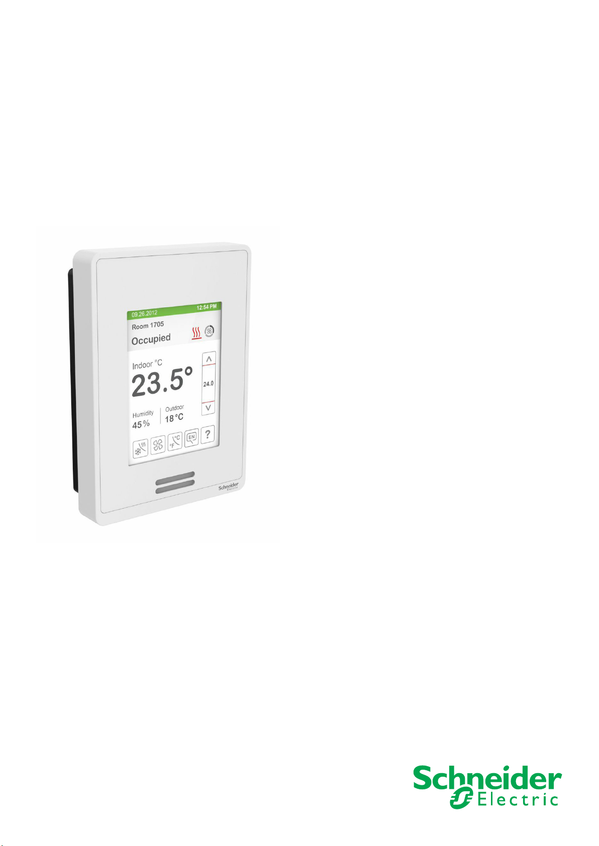
Commercial and Hospitality Interface (Local Override and Degrees C/F Selection)
Power
Part Number Description Humidity PIR
Sensor
SER8300
A0BXX
BACnet® fan coil terminal equipment controller
No No BACnet
Communication
®
3
SER8300A5BXX
SER8350
SER8350
SER8350
A0BXX
A5BXX
A0BxxLTD
BACnet® fan coil terminal equipment controller
BACnet® fan coil terminal equipment controller
BACnet® fan coil terminal equipment controller
BACnet® fan coil terminal equipment controller
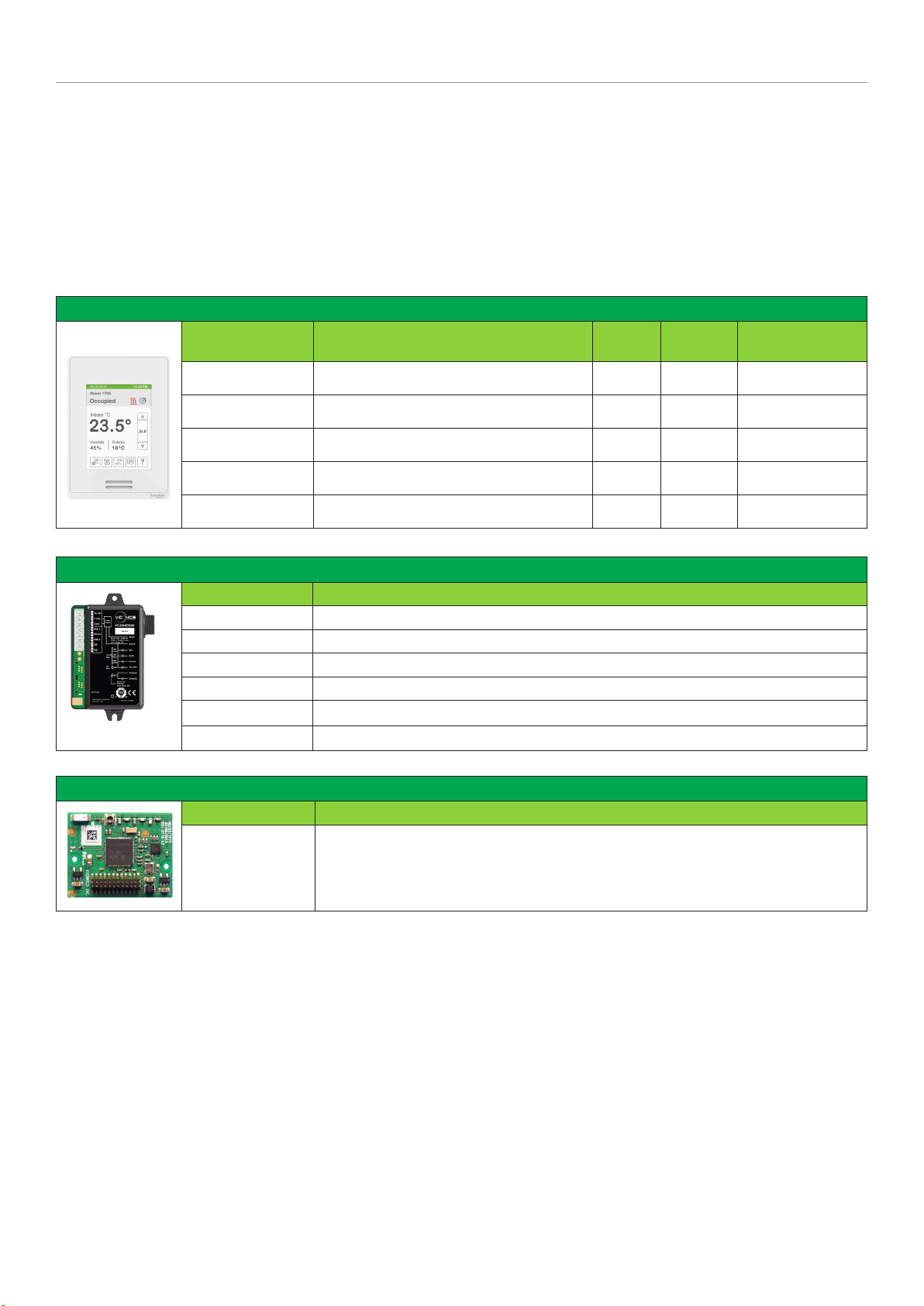
Transformer Relay Packs for Fan Coil Units
Power
Part Number Description
SC3500E5045 Transformer relay pack five relay fan outputs
SC3504E5045 Transformer relay pack five relay fan outputs, and four inputs
SC3514E5045 Transformer relay pack five relay outputs, smart VDC OCC output, and four inputs
SC3400E5045 Transformer relay pack four relay outputs and smart VDC output
SC3404E5045 Transformer relay pack four relay outputs, smart VDC output, and four inputs
SC3300E5045 Transformer relay pack three relay fan outputs
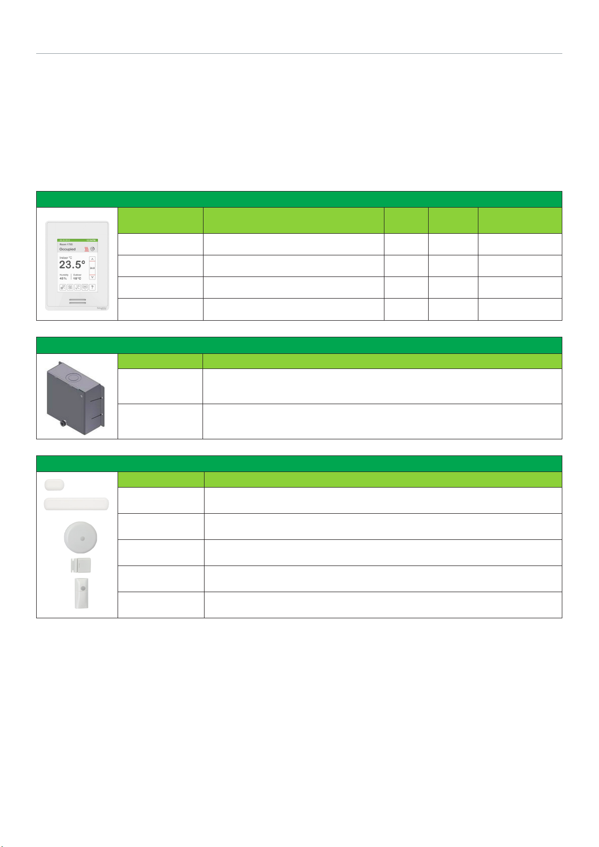
ZigBee Pro Module for SE(R)8300 Series
Part Number Description
Power
VCM8000V5045P Optional ZigBee Pro module for SE8300 Series room controllers.
No Ye s BACnet
Yes No BACnet
Yes Ye s BACnet
No No BACnet
4
Schneider Electric | AG-SER83 00-SE8 300-FCU-A4.EN.01.2016.v6 January 2016
SE8300 ROOM CONTROLLERS
This new cost-effective solution for upgrading low-voltage fan coil unit thermostats requires only the SE8300 Terminal
Equipment Controller.
The SE8300 Terminal Equipment Controller can also be used along with a SC1300 or SC2300 Relay Pack for mixed-voltage
solutions, when control of both line-voltage and low-voltage end devices is required.
Commercial and Hospitality Interface (Local Override and Degrees C/F Selection)
Power
Part Number Description Humidity PIR
Sensor
SE8300
U0BXX
BACnet® fan coil terminal equipment controller
No No BACnet
Communication
®
SE8300U5BXX
SE8350U0BXX
SE8350U5BXX
BACnet® fan coil terminal equipment controller
BACnet® fan coil terminal equipment controller
BACnet® fan coil terminal equipment controller
Mixed-voltage Relay Packs for SE8300 Series
Part Number Description
SC1300E5045
SC2300E5045
3 on/off outputs, 110/130V 3 speed
3 on/off outputs, 220/240V 3 speed
Wireless Accessories for SE(R)8300 Series
Power
Part Number Description
SED-DOR-P-5045 Wireless door switch
SED-WIN-P-5045 Wireless window switch
SED-CMS-P-5045 Wireless ceiling mounted motion sensor
No Ye s BACnet
Yes No BACnet
Yes Ye s BACnet
®
®
®
SED-WDS-P-5045 Wireless window and door switch
SED-WMS-P-5045 Wireless wall mounted motion sensor
Schneider Electric | AG-SER83 00-SE8 300-FCU-A4.EN.01.2016.v6 January 2016
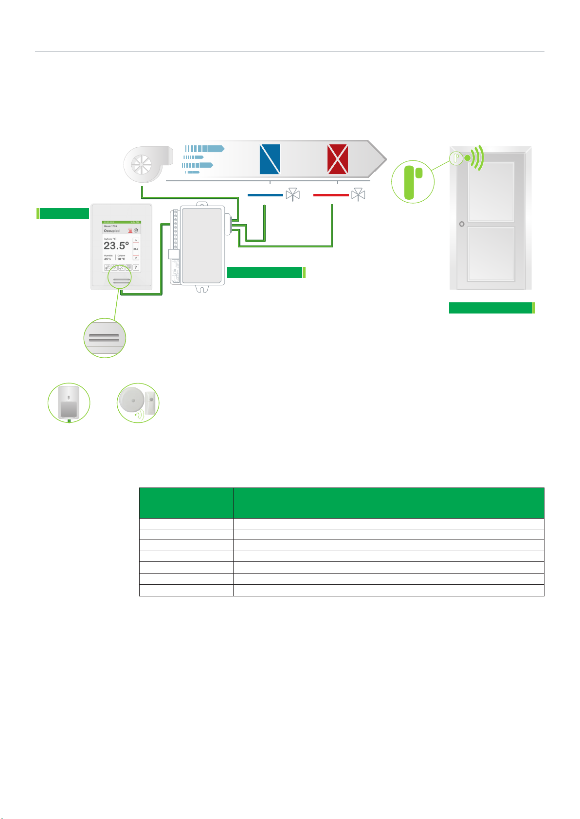
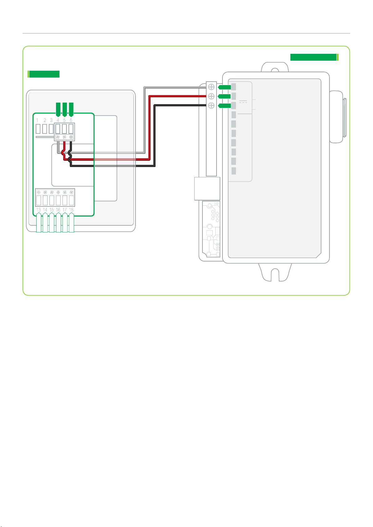
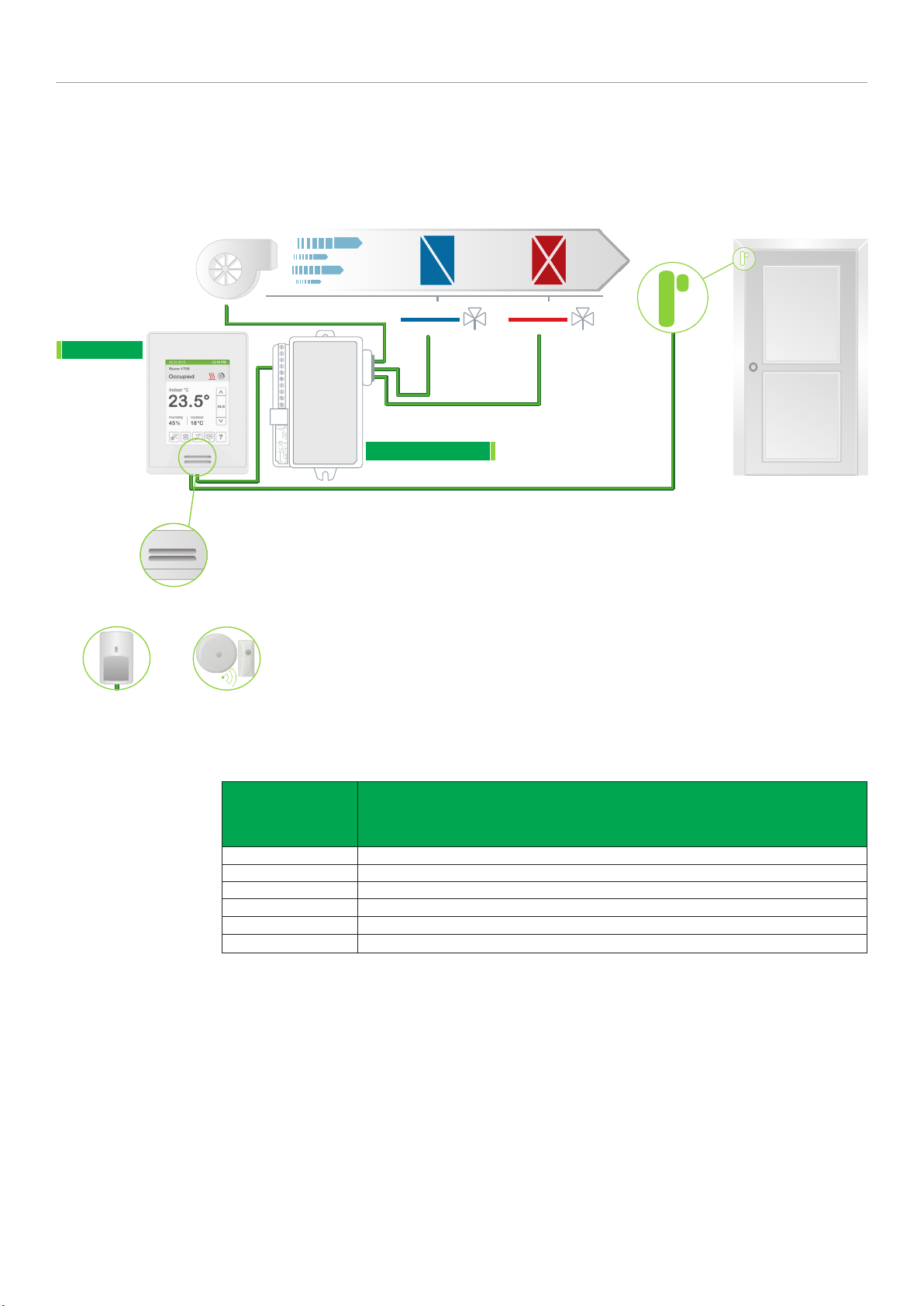
SER83X0XXBXX WITH SC3500E5045 RELAY: HEATING/COOLING 4-PIPE FAN COIL
UNIT WITH 3-SPEED FAN AND 2-POSITION VALVES WITH WIRELESS DOOR SWITCH
5
SER8300
Onboard
PIR Sensor
AND / OR
OR*
Fan
Airflow Direction
Cooling Coil
2 POSITION
COOLING VALVE
Heating Coil
2 POSITION
HEATING VALVE
SC3500E5045
Refer to the Schneider Electric Catalog for valves and actuators
Door Switch
SED-DOR-P-5045
Wired Remote
PIR Sensor
Wireless Remote
PIR Sensor
Configuration
Parameter Name
Fan Menu L-M-H-A
Fan cont. heat. On
BI1 Motion NO or Motion NC (remote PIR sensor only)
BI2 Door Dry
Pulsed heating Off
Pipe no. 4
Seq. operation Ht - Cl
Configuration Settings
* Wired remote sensor cannot be used at the same time as wireless remote sensor(s).
6
Schneider Electric | AG-SER83 00-SE8 300-FCU-A4.EN.01.2016.v6 January 2016
SER8300
7 VDC
Tx / Rx
Com
1
2
3
SC3500E5045
Tx/Rx
7 Vdc
Com
BACnet +
BACnet -
BACnet REF
BI 1
BI 2
Common
Sequence of Operation and Wiring
Occupied Mode
Setpoints revert to those defined by occupied cooling and
heating.
Stand-by Mode (only available when PIR motion detector
sensor is used)
Setpoints revert to those defined by stand-by cooling and
heating.
Unoccupied Mode
Setpoints revert to those defined by unoccupied heating and
cooling.
Occupied Override Mode
System reverts to occupied mode for duration determined by
“ToccTime” parameter.
On Call for Cool
Cooling valve opens to maintain room temperature. Heating
valve closed.
On Call for Heat
Heating valve opens to maintain room temperature. Cooling
valve closed.
Wireless Door Switch
Wireless door switch automatically toggles occupancy.
Options
• Wireless adapter modules for BACnet models are
available. (see Appendix B for network wiring).
• Can be configured for 2-pipe systems (without
changeover).
• Binary inputs can be configured to control occupancy via
door or window contact, remote motion sensor, or remote
night setback.
Schneider Electric | AG-SER83 00-SE8 300-FCU-A4.EN.01.2016.v6 January 2016
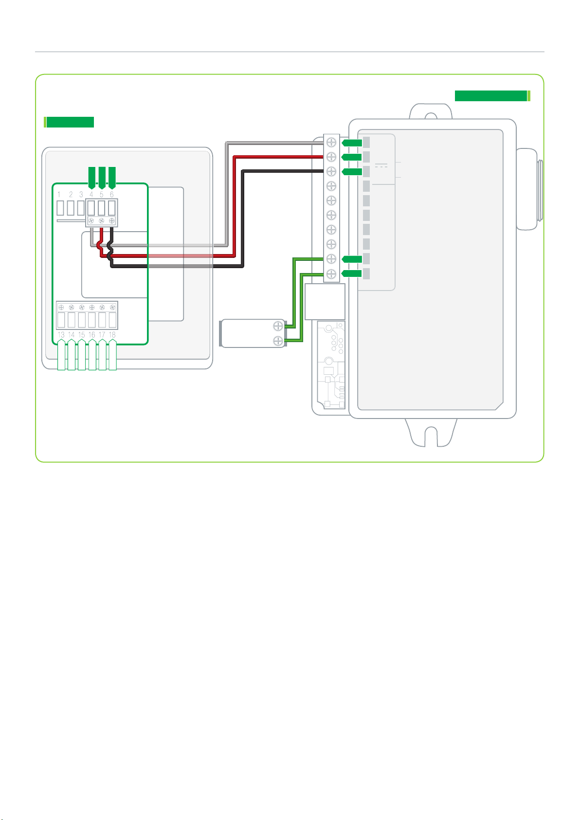
SER8350XXBXX WITH SC3404E5045 RELAY: COOLING AND ELECTRIC HEAT 2-PIPE FAN COIL UNIT
WITH 3-SPEED FAN, DEHUMIDIFICATION AND 2-POSITION VALVES
7
SER8300
Fan
Airflow Direction
Cooling Coil Electric Heating
2 POSITION
COOLING VALVE
SOLID STATE RELAY
SC3404E5045
Refer to Schneider Electric Catalog for valves and actuators.
SSR
(GENERIC)
Configuration
parameter name
Pulsed heating On
Pipe no. 2
Seq. operation Ht-Cl
Fan menu L-M-H-A
Fan cont. heat On
Configuration settings
8
Schneider Electric | AG-SER83 00-SE8 300-FCU-A4.EN.01.2016.v6 January 2016
SER8300
7 VDC
Tx / Rx
Com
1
2
3
4
5
6
7
8
9
10
SC3404E5045
Tx/Rx
7 Vdc
Com
RUI 1
SCom
RBI 2
SS
RS
Heat -
Heat +
SOLIDSTATE
RELAY
(4-32Vdc)
BACnet +
BACnet -
BACnet REF
BI 1
BI 2
Common
(-)
(+)
Sequence of Operation and Wiring
Occupied Mode
Setpoints revert to those defined by occupied cooling and
heating.
Stand-by Mode (only available when PIR motion detector
sensor is used)
Setpoints revert to those defined by stand-by cooling and
heating.
Unoccupied Mode
Setpoints revert to those defined by unoccupied heating and
cooling.
Occupied Override Mode
System reverts to occupied mode for duration determined by
“ToccTime” parameter.
On Call for Cool
Cooling valve opens to maintain room temperature.
On Call for Heat
Electric heat operates to maintain room temperature. Cooling
valve closes and dehumidification is disabled.
On a Demand for Dehumidification
Dehumidification achieved via cooling coil using reheat if
necessary.
Dehumidification only allowed in COOL mode or if cooling is
enabled in AUTO mode.
Dehumidification disabled if room temperature falls below
low ambient lockout temperature, which is cooling setpoint
minus configuration defined deadband value.
Options
• Wireless adapter modules for BACnet models are
available. (see Appendix B for network wiring).
• Remote wall mount or return duct sensor ready.
• Can be configured for 2-pipe systems with changeover.
• Binary inputs can be configured to control occupancy via
door or window contact, remote motion sensor, remote
night setback, or provide alarms for service or filter
monitoring.
• Universal input can be configured for changeover sensor.
Schneider Electric | AG-SER83 00-SE8 300-FCU-A4.EN.01.2016.v6 January 2016
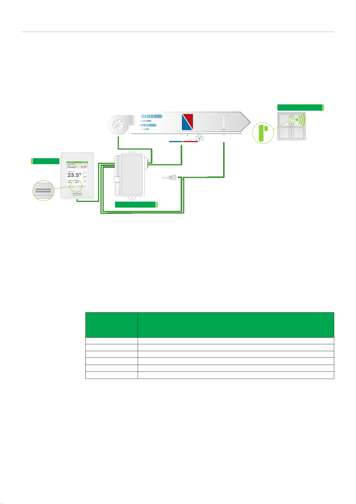
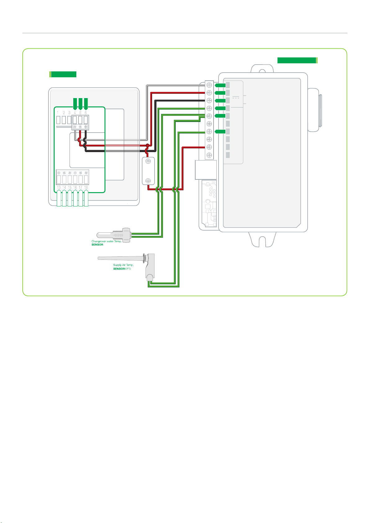
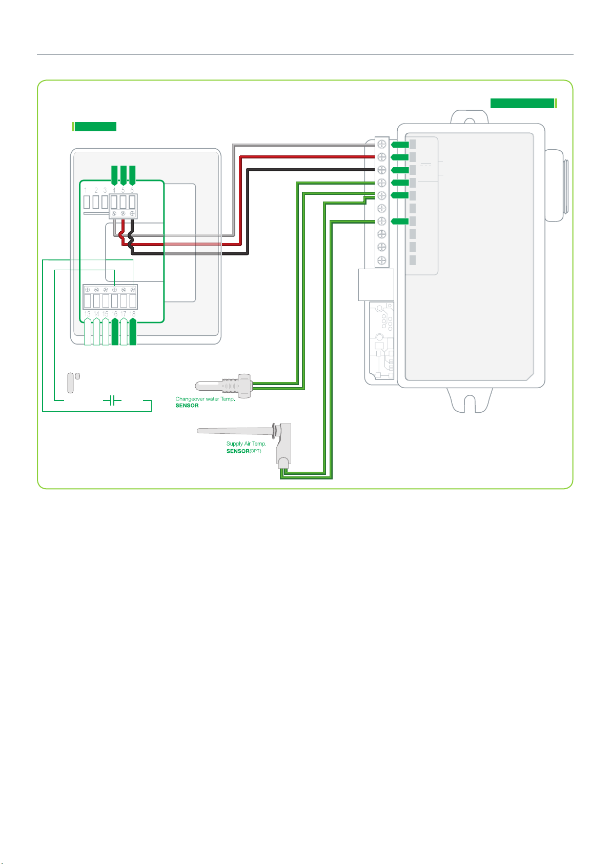
SER8300XXBXX WITH SC3504E5045 RELAY: HEATING/COOLING WITH CHANGEOVER SENSOR
2-PIPE FAN COIL UNIT WITH 3-SPEED FAN AND WIRELESSS WINDOW SWITCH
Window Switch
Fan
Airflow Direction
Cooling / Heating Coil Supply Sensor
SED-WIN-P-5000
9
SER8300
Onboard
PIR Sensor
2 POSITION
COOLING VALVE / HEATING VALVE
C/O
SENSOR
SENSOR
SC3504E5045
Changeover Sensor: 10K Ohm type 2
Supply Sensor: 10K Ohm type 2
Refer to Schneider Electric Catalog for valves and actuators.
Configuration
Parameter
Name
Fan Menu L-M-H-A
Fan cont. heat On
BI1 Window
RUI1 COS
Pipe No 2
Seq. operation Cool
Configuration Settings
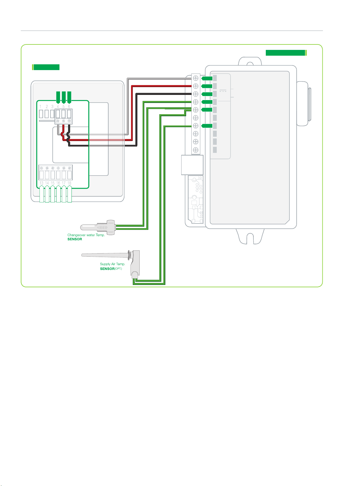
10
Schneider Electric | AG-SER83 00-SE8 300-FCU-A4.EN.01.2016.v6 January 2016
SC3504E5045
SER8300
7 VDC
Tx / Rx
Com
1
2
3
4
5
6
7
8
Tx/Rx
7 Vdc
Com
RUI 1
SCom
RBI 2
SS
RS
BACnet +
BACnet -
BACnet REF
BI 1
BI 2
Common
Sequence of Operation and Wiring
Occupied Mode
Setpoints revert to those defined by occupied cooling and
heating.
Stand-by Mode (only available when PIR motion detector
sensor is used)
Setpoints revert to those defined by stand-by cooling and
heating.
Unoccupied Mode
Setpoints revert to those defined by unoccupied heating and
cooling.
Occupied Override Mode
System reverts to occupied mode for duration determined by
“ToccTime” parameter.
On Call for Cool
If supply water temperature is less than 24°C (75F), valve
opens to maintain room temperature, else valve closes.
On Call for Heat
If supply water temperature is greater than 25°C (77F), valve
opens to maintain room temperature, else the valve closes.
Supply Air Sensor
Only used for monitoring. Shows automatically if sensor is
connected.
Wireless Window Switch
Wireless window switch automatically locks out heating/
cooling when window is opened.
Options
• Wireless adapter modules for BACnet models are
available. (see Appendix B for network wiring).
• Remote wall mount or return duct sensor ready.
• Binary inputs can be configured to control occupancy via
door or window contact, remote motion sensor, remote
night setback, or provide alarms for service or filter
monitoring.
Schneider Electric | AG-SER83 00-SE8 300-FCU-A4.EN.01.2016.v6 January 2016
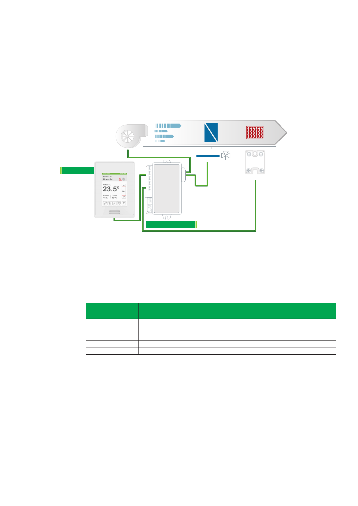
SER8350XXBXX WITH SC3400E5045 RELAY: COOLING AND ELECTRIC HEAT 2-PIPE FAN COIL UNIT
WITH 3-SPEED FAN, DEHUMIDIFICATION AND 2-POSITION VALVES
11
SER8300
Fan
Airflow Direction
Cooling Coil Electric Heating
2 POSITION
COOLING VALVE
SOLID STATE RELAY
SC3400E5045
Refer to Schneider Electric Catalog for valves and actuators.
SSR
(GENERIC)
Configuration
parameter name
Configuration settings
Fan menu L-M-H-A
Fan cont. heat. On
Pulsed Heating On
Pipe No 2
Seq. operation Ht-Cl
12
Schneider Electric | AG-SER83 00-SE8 300-FCU-A4.EN.01.2016.v6 January 2016
SC3400E5045
SER8300
7 VDC
Tx / Rx
Com
1
2
3
9
10
SOLIDSTATE
RELAY
(4-32Vdc)
BACnet +
BACnet -
BACnet REF
BI 1
BI 2
Common
(-)
(+)
Sequence of Operation and Wiring
Occupied Mode
Setpoints revert to those defined by occupied cooling and
heating.
Stand-by Mode (only available when PIR motion detector
sensor is used)
Setpoints revert to those defined by stand-by cooling and
heating.
Unoccupied Mode
Setpoints revert to those defined by unoccupied heating and
cooling.
Occupied Override Mode
System reverts to occupied mode for duration determined by
“ToccTime” parameter.
On Call for Cool
Cooling valve opens to maintain room temperature.
On Call for Heat
Electric heat operates to maintain room temperature. Cooling
valve closed and dehumidification is disabled.
On a Demand for Dehumidification
Dehumidification achieved via cooling coil using reheat if
necessary.
Dehumidification only allowed in COOL mode or if cooling is
enabled in AUTO mode.
Dehumidification disabled if room temperature falls below
low ambient lockout temperature, which is cooling setpoint
minus configuration defined deadband value.
Options
• Wireless adapter modules for BACnet models are
available. (see Appendix B for network wiring).
• Binary inputs can be configured to control occupancy via
door or window contact, remote motion sensor, remote
night setback, or provide alarms for service or filter
monitoring.
Schneider Electric | AG-SER83 00-SE8 300-FCU-A4.EN.01.2016.v6 January 2016
SER8300XXBXX WITH SC3514E5045 RELAY: HEATING/COOLING 2-PIPE FAN COIL UNIT WITH
3-SPEED FAN, FRESH AIR DAMPER AND 2-POSITION VALVES
13
SER8300
Fresh Air
DAMPER
Return Air
Fan
Airflow Direction
SC3514E5045
Cooling / Heating Coil Supply Sensor
2 POSITION
COOLING VALVE / HEATING VALVE
C/O
SENSOR
Supply Sensor: 10K Ohm type 2.
Changeover Sensor: 10K Ohm type 2.
Refer to Schneider Electric Catalog for
valves and actuators.
SENSOR
Configuration
Parameter
Name
Fan menu L-M-H-A
Fan cont. heat On
RUI1 COS
Pulsed Heating Occ Out
Pipe no. 2
Seq. operation Cool
Configuration Settings
14
Schneider Electric | AG-SER83 00-SE8 300-FCU-A4.EN.01.2016.v6 January 2016
SER8300
Tx / Rx
7 VDC
Com
7Vdc
RELAY
COIL
1
2
3
4
5
6
7
8
9
SC3514E5045
Tx/Rx
7 Vdc
Com
RUI 1
SCom
RBI 2
SS
RS
OCC -
BACnet +
BACnet -
BACnet REF
BI 1
BI 2
Common
Sequence of Operation and Wiring
Occupied Mode
Setpoints revert to those defined by occupied cooling and
heating. The occupancy output opens fresh air damper to
minimum position.
Stand-by Mode (only available when PIR motion detector
sensor is used)
Setpoints revert to those defined by stand-by cooling and
heating.
Unoccupied Mode
Setpoints revert to those defined by unoccupied heating and
cooling. The fresh air damper closes.
Occupied Override Mode
System reverts to occupied mode for duration determined by
“ToccTime” parameter.
On Call for Cool
If supply water temperature is less than 24°C (75F), cooling
valve opens to maintain room temperature, else the valve
closes.
On Call for Heat
If supply water temperature is greater than 25°C (77F),
heating valve opens to maintain room temperature, else the
valve closes.
Supply Air Sensor
Only used for monitoring. Shows automatically if sensor is
connected.
Options
• Wireless adapter modules for BACnet models are
available. (see Appendix B for network wiring).
• Remote wall mount or return duct sensor ready.
• Binary inputs can be configured to control occupancy via
door or window contact, remote motion sensor, remote
night setback, or provide alarms for service or filter
monitoring.
Schneider Electric | AG-SER83 00-SE8 300-FCU-A4.EN.01.2016.v6 January 2016
SER8300XXBXX WITH SC3500E5045 AND SC3300E5045 RELAYS: HEATING/COOLING 4-PIPE FAN
COIL UNIT WITH 3-SPEED FAN AND 2-POSITION VALVES WITH SLAVE RELAY PACK
Airflow Direction
Fan
Cooling Coil
Heating Coil
15
SER8300
SC3300E5045
Configuration
Parameter Name
Fan menu L-M-H-A
Fan cont. heat On
Pipe No 4
Seq. operation Ht-Cl
Configuration Settings
2 POSITION
COOLING VALVE
SC3500E5045
2 POSITION
HEATING VALVE
Refer to Schneider Electric
Catalog for valves and
actuators.
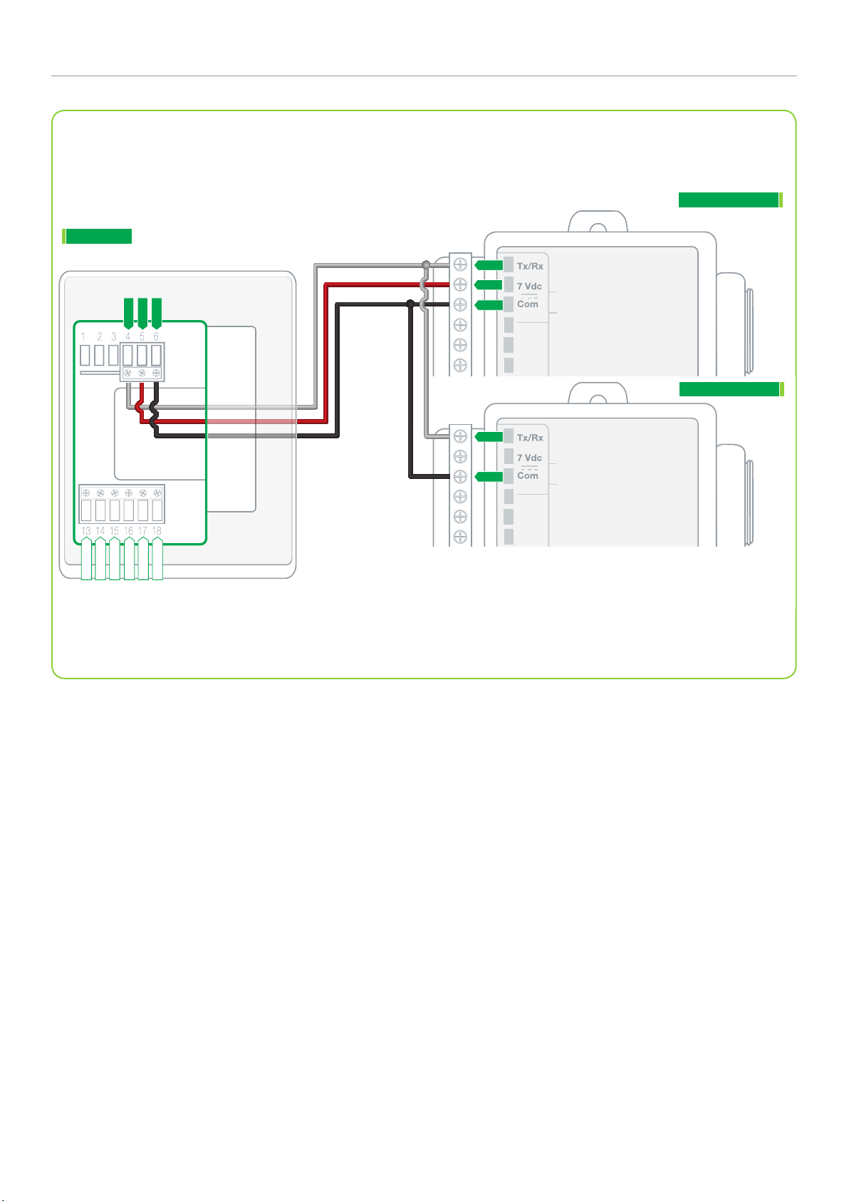
16
Schneider Electric | AG-SER83 00-SE8 300-FCU-A4.EN.01.2016.v6 January 2016
SER8300
7 VDC
Tx / Rx
Com
SC3300E5045
1
2
3
SC3500E5045
1
2
3
BACnet +
BACnet -
BACnet REF
BI 1
BI 2
Common
Sequence of Operation and Wiring
Occupied Mode
Setpoints revert to those defined by occupied cooling and
heating.
Stand-by Mode (only available when PIR motion detector
sensor is used)
Setpoints revert to those defined by stand-by cooling and
heating.
Unoccupied Mode
Setpoints revert to those defined by unoccupied heating and
cooling.
Occupied Override Mode
System reverts to occupied mode for duration determined by
“ToccTime” parameter.
On Call for Cool
Cooling valve opens to maintain room temperature. Heating
valve closes.
On Call for Heat
Heating valve opens to maintain room temperature. Cooling
valve closes.
Options
• Wireless adapter modules for BACnet models are
available. (see Appendix B for network wiring).
• Can be configured for 2-pipe systems without
changeover.
• Binary inputs can be configured to control occupancy via
door or window contact, remote motion sensor, remote
night setback, or provide alarms for service or filter
monitoring.
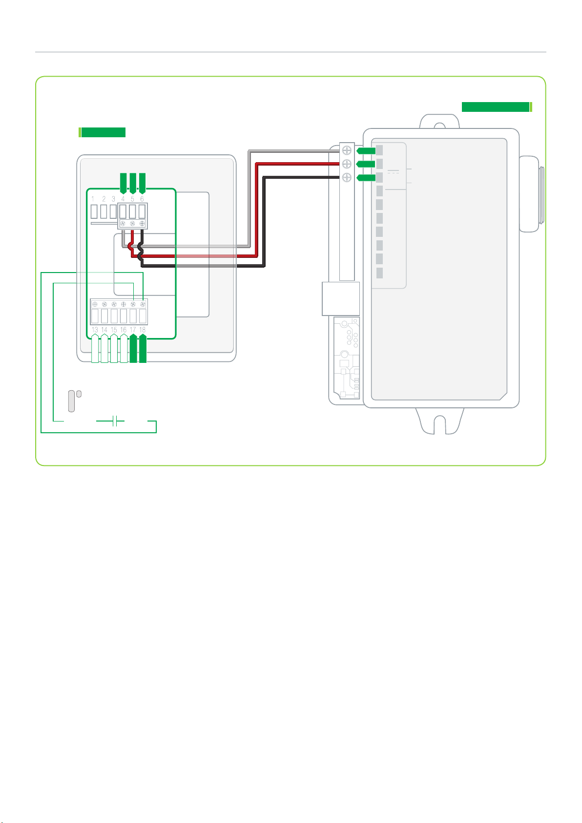
Schneider Electric | AG-SER83 00-SE8 300-FCU-A4.EN.01.2016.v6 January 2016
SER83X0XXBXX WITH SC3504E5045 RELAY: COOLING AND ELECTRIC HEAT
2-PIPE FAN COIL UNIT WITH 3-SPEED FAN AND 2-POSITION VALVES WITH WIRED WINDOW SWITCH
17
SER8300
Onboard
PIR Sensor
Fan
Airflow Direction
Cooling / Heating Coil Supply Sensor
2 POSITION
COOLING VALVE / HEATING VALVE
C/O
SENSOR
SC3504E5045
Changeover Sensor: 10K Ohm type 2
Supply Sensor: 10K Ohm type 2
Refer to Schneider Electric Catalog for valves and actuators.
Window Switch
SENSOR
Configuration Parameter
Name
Fan menu L-M-H-A
Fan cont. heat On
BI1 Window
RUI1 COS
Pipe no. 2
Seq. operation Cool
Configuration Settings
18
Schneider Electric | AG-SER83 00-SE8 300-FCU-A4.EN.01.2016.v6 January 2016
SC3504E5045
SER8300
Tx / Rx
7 VDC
Com
1
2
3
4
5
6
7
8
Tx/Rx
7 Vdc
Com
RUI 1
SCom
RBI 2
SS
RS
BACnet +
BACnet -
BACnet REF
BI 1
BI 2
Common
BI1 (Window)
SCom
Sequence of Operation and Wiring
Occupied Mode
Setpoints revert to those defined by occupied cooling and
heating.
Stand-by Mode (only available when PIR motion detector
sensor is used)
Setpoints revert to those defined by stand-by cooling and
heating.
Unoccupied Mode
Setpoints revert to those defined by unoccupied heating and
cooling.
Occupied Override Mode
System reverts to occupied mode for duration determined by
“ToccTime” parameter.
On Call for Cool
If supply water temperature is less than 24°C (75F), cooling
valve opens to maintain room temperature, else the valve
closes.
On Call for Heat
If supply water temperature is greater than 25°C (77F),
heating valve opens to maintain room temperature, else the
valve closes.
Supply Air Sensor
Only used for monitoring. Shows automatically if sensor is
connected.
Wired Window Switch
The window switch automatically locks out heating/cooling
when window opens.
Options
• Wireless adapter modules for BACnet models are
available. (see Appendix B for network wiring).
• Models available with factory installed PIR sensor.
• Remote wall mount or duct sensor ready.
• Can be configured for 2-pipe systems with changeover.
• Binary inputs can be configured to control occupancy via
door or window contact, remote night setback, or provide
alarms for service or filter monitoring.
• Universal input can be configured for changeover sensor.
19
Schneider Electric | AG-SER83 00-SE8 300-FCU-A4.EN.01.2016.v6 January 2016
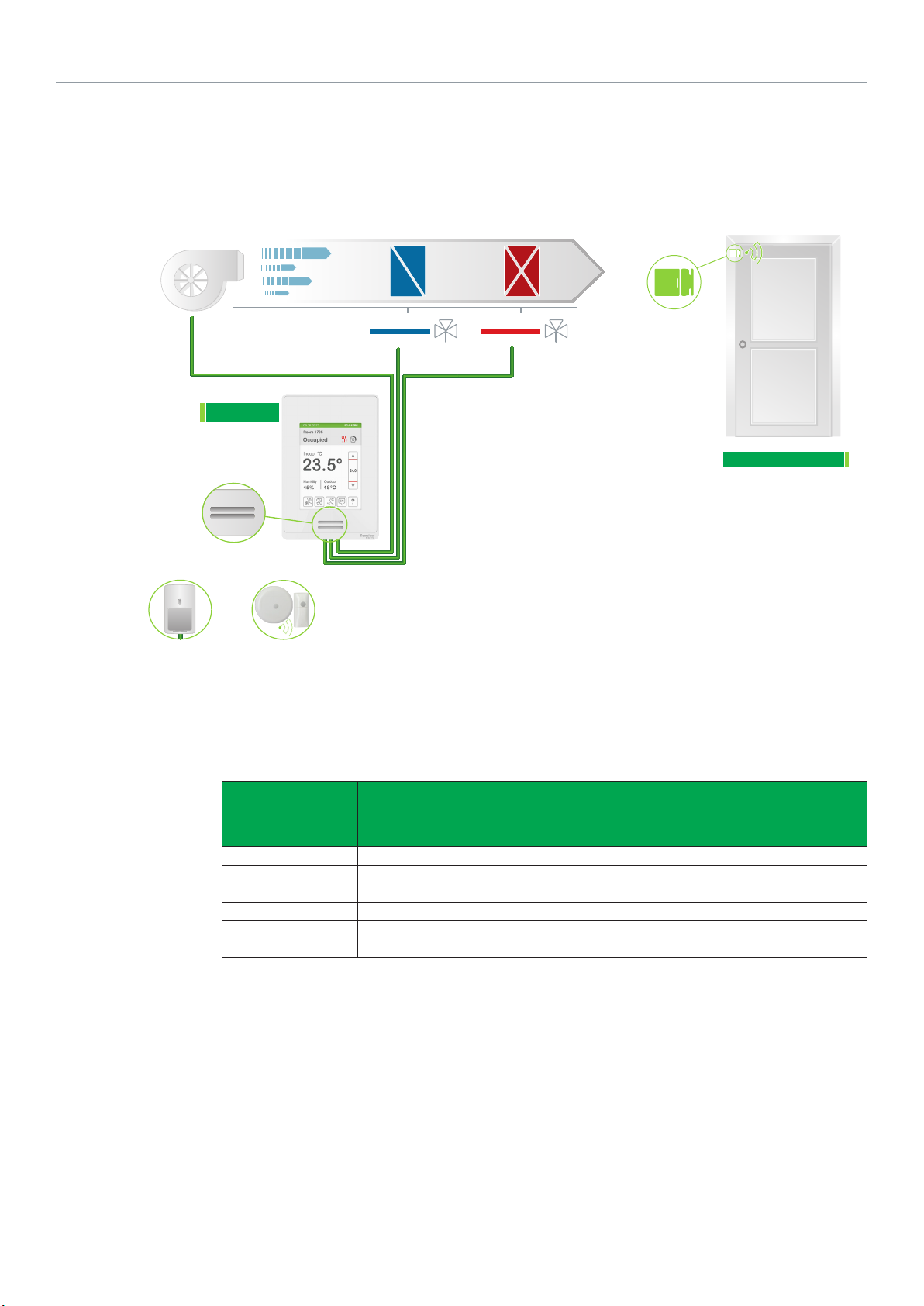
SER8300XXBXX WITH SC3500E5045 RELAY: HEATING/COOLING 4-PIPE FAN COIL UNIT WITH 3-SPEED
FAN AND 2-POSITION VALVES WITH WIRED DOOR SWITCH
SER8300
Onboard
PIR Sensor
AND / OR
OR*
Fan
Airflow Direction
Cooling Coil
2 POSITION
COOLING VALVE
Heating Coil
2 POSITION
HEATING VALVE
SC3500E5045
Refer to Schneider Electric Catalog for valves and actuators.
Wired Window Switch
Wired Remote
PIR Sensor
Wireless Remote
PIR Sensor
Configuration
Parameter
Name
Fan menu L-M-H-A
Fan cont. heat On
BI1 Motion NO or Motion NC (remote PIR sensor only)
BI2 Door Dry
Pipe No 4
Seq. Operat Ht-Cl
Configuration Settings
20
Schneider Electric | AG-SER83 00-SE8 300-FCU-A4.EN.01.2016.v6 January 2016
SC3500E5045
SER8300
7 VDC
Tx / Rx
Com
1
2
3
Tx/Rx
7 Vdc
Com
BACnet +
BACnet -
BACnet REF
BI 1
BI 2
Common
BI2 (Door)
SCom
Sequence of Operation and Wiring
Occupied Mode
Setpoints revert to those defined by occupied cooling and
heating.
Stand-by Mode (only available when PIR motion detector
sensor is used)
Setpoints revert to those defined by stand-by cooling and
heating.
Unoccupied Mode
Setpoints revert to those defined by unoccupied heating and
cooling.
Occupied Override Mode
System reverts to occupied mode for duration determined by
“ToccTime” parameter.
On Call for Cool
Cooling valve opens to maintain room temperature. Heating
valve closes.
On Call for Heat
Heating valve opens to maintain room temperature. Cooling
valve closes.
Door Switch
Door switch automatically toggles occupancy.
Options
• Wireless adapter modules for BACnet models are
available. (see Appendix B for network wiring).
• Models available with factory installed PIR sensor.
• Can be configured for 2-pipe systems without
changeover.
• Binary inputs can be configured to control occupancy via
door or window contact, remote motion sensor, remote
night setback, or provide alarms for service or filter
monitoring.
Schneider Electric | AG-SER83 00-SE8 300-FCU-A4.EN.01.2016.v6 January 2016
SE8350UXBXX HEATING/COOLING 4-PIPE FAN COIL UNIT WITH 3-SPEED FAN, TRI-STATE FLOATING
VALVES
AND DEHUMIDIFICATION SEQUENCE FOR LOW VOLTAGE WITH WIRELESS DOOR SWITCH
21
Fan
SE8300
Onboard
PIR Sensor
AND / OR
Wired Remote
PIR Sensor
Airflow Direction
OR*
Wireless Remote
PIR Sensor
Cooling Coil
TRI-STATE
COOLING VALVE
Heating Coil
TRI-STATE
HEATING VALVE
Door Switch
SED-WDS-P-5045
Refer to Schneider Electric
Catalog for valves and actuators
Configuration
Parameter
Configuration Settings
Name
Fan menu L-M-H-A
Control Type Floating
UI16 Motion NO or Motion NC (remote PIR sensor only)
UI17 Door Dry
Pipe no. 4
Seq. operation Cool / Heat
* Wired remote sensor cannot be used at the same time as wireless remote sensor(s).

22
Schneider Electric | AG-SER83 00-SE8 300-FCU-A4.EN.01.2016.v6 January 2016
SE8300
BO2 - Fan L
1 2 3 4 5 6
1 2 3 4 5 6
13 14 15 16 17 18
13 14 15 16 17 18
RC (24 Vac)
BO4 - Fan H
BO3 - Fan M
C (Common)
Floating Control
RH
- Close Cool V
BO8 - Aux Heat
UO9
UO11 - Open Cool V
UO12 - Open Heat V
UO10 - Close Heat V
7 8 9 10 11 12
7 8 9 10 11 12
19 20 21 22 23 24
19 20 21 22 23 24
HEATING VALVE
Close Open Com.
COOLING VALVE
Close Open Com.
FCU Low-voltage
TERMINAL BLOCK
COMM ON
24 VAC
FAN HI
FAN MED
FAN LO
UI 19
UI 20 - RS
Common
BACnet +
BACnet -
BACnet REF
UI 16
UI 17
Common
UI22 - SS
Sequence of Operation and Wiring
Occupied Mode
Setpoints revert to those defined by occupied cooling and
heating.
Stand-by Mode (only available when PIR motion detector
sensor is used)
Setpoints revert to those defined by stand-by cooling and
heating.
Unoccupied Mode
Setpoints revert to those defined by unoccupied heating and
cooling.
Occupied Override Mode
System reverts to occupied mode for duration determined by
“ToccTime” parameter.
On Call for Cool
Cooling valve opens to maintain room temperature. Heating
valve closes.
On Call for Heat
Heating valve opens to maintain room temperature. Cooling
valve closes.
On Demand for Dehumidification
Dehumidification is achieved via cooling coil using heating
coil for reheat if necessary.
Dehumidification is only allowed in COOL mode, or if cooling
is enabled in AUTO mode.
Dehumidification is disabled if room temperature falls
below low ambient lockout temperature, which is the cooling
setpoint minus the configuration defined deadband value.
Reheat disabled if cooling demand reaches 100%.
Options
• Wireless adapter modules for BACnet models are
available. (see Appendix B for network wiring).
• Remote wall mount or duct sensor ready.
• Can be configured for 2-pipe systems with changeover.
• 3 universal inputs can be used and configured for
advanced functionality as required by the application.
• Universal input can be configured for changeover sensor.

23
Schneider Electric | AG-SER83 00-SE8 300-FCU-A4.EN.01.2016.v6 January 2016
SE8350UXBXX HEATING/COOLING 4-PIPE FAN COIL UNIT WITH 3-SPEED FAN, 0-10 VDC ANALOG
VALVES AND DEHUMIDIFICATION SEQUENCE FOR LOW VOLTAGE AND WIRELESS WINDOW SWITCH
Fan
SE8300
Onboard
PIR Sensor
Airflow Direction
Cooling Coil
ANALOG
COOLING VALVE
Heating Coil
ANALOG
HEATING VALVE
Window Switch
SED-WDS-P-5045
Refer to Schneider Electric Catalog for valves and
actuators
Configuration
Parameter
Name
Fan menu L-M-H-A
UI16 Window
Pipe no. 4
Seq. operation Cool / Heat
Configuration Settings

24
Schneider Electric | AG-SER83 00-SE8 300-FCU-A4.EN.01.2016.v6 January 2016
SE8300
BO2 - Fan L
1 2 3 4 5 6
1 2 3 4 5 6
13 14 15 16 17 18
13 14 15 16 17 18
RC (24 Vac)
BO4 - Fan H
BO3 - Fan M
C (Common)
Modulating Control
RH
7 8 9 10 11 12
7 8 9 10 11 12
19 20 21 22 23 24
19 20 21 22 23 24
V
BO8 - Aux Heat
- Analog Heat
UO12 - Analog Cool
UO11
HEATING VALVE
.
COOLING VALVE
.
FCU Low-voltage
TERMINAL BLOCK
COMM ON
24 VAC
FAN HI
FAN MED
FAN LO
UI 19
UI 20 - RS
Common
BACnet +
BACnet -
BACnet REF
UI 16
UI 17
Common
UI22 - SS
Sequence of Operation and Wiring
Occupied Mode
Setpoints revert to those defined by occupied cooling
and heating. The changeover sensor sends supply air
temperature to controller.
Stand-by Mode (only available when PIR motion detector
sensor is used)
Setpoints revert to those defined by stand-by cooling and
heating.
Unoccupied Mode
Setpoints revert to those defined by unoccupied heating and
cooling.
Occupied Override Mode
System reverts to occupied mode for duration determined by
“ToccTime” parameter.
On Call for Cool
Cooling valve opens to maintain room temperature. Heating
valve closes. Dehumidification enabled.
On Call for Heat
Heating valve opens to maintain room temperature. Cooling
valve closes. Dehumidification disabled.
On Demand for Dehumidification
Dehumidification is achieved via cooling coil using heating
coil for reheat if necessary.
Dehumidification only allowed in COOL mode, or if cooling is
enabled in AUTO mode.
Dehumidification disabled if room temperature falls below
low ambient lockout temperature, which is cooling setpoint
minus configuration defined deadband value.
Reheat disabled if cooling demand reaches 100%.
Options
• Wireless adapter modules for BACnet models are
available. (see Appendix B for network wiring).
• Remote wall mount or duct sensor ready.
• Can be configured for 2-pipe systems.
• 3 universal inputs can be used and configured for
advanced functionality as required by the application.
• Universal input can be configured for changeover sensor.

Schneider Electric | AG-SER83 00-SE8 300-FCU-A4.EN.01.2016.v6 January 2016
SE8355UXBXX HEATING/COOLING 4-PIPE FAN COIL UNIT WITH 3-SPEED FAN, 2-POSITION VALVES
AND DEHUMIDIFICATION SEQUENCE FOR LOW VOLTAGE
25
Fan
SE8300
Airflow Direction
Cooling Coil
2 POSITION
COOLING VALVE
Heating Coil
2 POSITION
HEATING VALVE
Refer to Schneider Electric Catalog for valves and
actuators
Configuration
Parameter
Name
Fan menu L-M-H-A
Control Type On/Off
Pipe no. 4
Seq. operation Cool/Heat
Configuration Settings

26
Schneider Electric | AG-SER83 00-SE8 300-FCU-A4.EN.01.2016.v6 January 2016
SE8300
BO2 - Fan L
1 2 3 4 5 6
1 2 3 4 5 6
13 14 15 16 17 18
13 14 15 16 17 18
RC (24 Vac)
BO4 - Fan H
BO3 - Fan M
C (Common)
On / Off Control
RH
- NC Cool V
UO9
BO8 - Aux Heat
UO10 -NC Heat V
UO11 - NO Cool V
UO12 - NO Heat V
7 8 9 10 11 12
7 8 9 10 11 12
19 20 21 22 23 24
19 20 21 22 23 24
HEATING VALVE
IF NC IF NO Com.
OR
COOLING VALVE
IF NC IF NO Com.
OR
FCU Low-voltage
TERMINAL BLOCK
COMM ON
24 VAC
FAN HI
FAN MED
FAN LO
UI 19 - UI13
UI 20 - RS
SCom
BACnet +
BACnet -
BACnet REF
UI 16 - BI1
UI 17 - BI2
SCom
UI22 - SS
Sequence of Operation and Wiring
Occupied Mode
Setpoints revert to those defined by occupied cooling and
heating.
Stand-by Mode (only available when PIR motion detector
sensor is used)
Setpoints revert to those defined by stand-by cooling and
heating.
Unoccupied Mode
Setpoints revert to those defined by unoccupied heating and
cooling.
Occupied Override Mode
System reverts to occupied mode for duration determined by
“ToccTime” parameter.
On Call for Cool
Cooling valve opens to maintain room temperature. Heating
valve closes. Dehumidification enabled.
On Call for Heat
Heating valve opens to maintain room temperature. Cooling
valve closes. Dehumidification disabled.
On Demand for Dehumidification
Dehumidification is achieved via cooling coil using heating
coil for reheat if necessary.
Dehumidification only allowed in COOL mode, or if cooling is
enabled in AUTO mode.
Dehumidification disabled if room temperature falls below
low ambient lockout temperature, which is cooling setpoint
minus configuration defined deadband value.
Reheat disabled if cooling demand reaches 100%.
Options
• Wireless adapter modules for BACnet models are
available. (see Appendix B for network wiring).
• Models available with factory installed PIR sensor.
• Remote wall mount or duct sensor ready.
• Can be configured for 2-pipe systems.
• 3 universal inputs can be used and configured for
advanced functionality as required by the application.
• Universal input can be configured for changeover sensor.

Schneider Electric | AG-SER83 00-SE8 300-FCU-A4.EN.01.2016.v6 January 2016
SE8300UXBXX COOLING ONLY 2-PIPE FAN COIL UNIT WITH SINGLE SPEED FAN, 2-POSITION
COOLING VALVE AND FRESH AIR DAMPER FOR LOW VOLTAGE
27
Fresh Air
DAMPER
Return Air
SE8300
Fan
Airflow Direction
Cooling Coil
2 POSITION
COOLING VALVE
Refer to Schneider Electric
Catalog for valves and actuators
Configuration
Parameter
Name
Fan menu L-M-H-A
Control Type On/Off
BO8 AuxOut Aux NO
Pipe no. 2
Seq. operation Cool only
Configuration Settings

28
Schneider Electric | AG-SER83 00-SE8 300-FCU-A4.EN.01.2016.v6 January 2016
SE8300
BO2 - Fan L
1 2 3 4 5 6
1 2 3 4 5 6
RC (24 Vac)
BO3 - Fan M
BO4 - Fan H
C (Common)
On / Off Control
RH
NC Cool V
UO9 -
BO8 - Aux Heat
7 8 9 10 11 12
7 8 9 10 11 12
UO10 - NC Heat V
UO11 - NO Cool V
UO12 - NO Heat V
FRESH AIR DAMPER
ON / OFF ACTUATOR
COOLING VALVE
IF NC IF NO Com.
OR
FCU Low-voltage
TERMINAL BLOCK
COMM ON
24 VAC
13 14 15 16 17 18
13 14 15 16 17 18
BACnet +
BACnet -
BACnet REF
UI 16 - BI1
UI 17 - BI2
SCom
19 20 21 22 23 24
19 20 21 22 23 24
UI 19 - UI13
UI 20 - RS
SCom
UI22 - SS
Sequence of Operation and Wiring
Occupied Mode
Setpoints revert to those defined by occupied cooling and
heating. The auxiliary contact closes forcing fresh air damper
to its minimum position.
Stand-by Mode (only available when PIR motion detector
sensor is used)
Setpoints revert to those defined by stand-by cooling and
heating.
Unoccupied Mode
Setpoints revert to those defined by unoccupied heating and
cooling. The auxiliary contact opens causing fresh air damper
to close completely.
Occupied Override Mode
System reverts to occupied mode for duration determined by
“ToccTime” parameter. The auxiliary contact closes forcing
fresh air damper to its minimum position.
On Call for Cool
Cooling valve opens.
On Call for Heat
Cooling valve closes.
FAN
Options
• Wireless adapter modules for BACnet models are
available. (see Appendix B for network wiring).
• Remote wall mount or duct sensor ready.
• Can be configured for 4-pipe systems.
• 3 universal inputs can be used and configured for
advanced functionality as required by the application.
• Can be configured for two speed or three speed fan
control.

Schneider Electric | AG-SER83 00-SE8 300-FCU-A4.EN.01.2016.v6 January 2016
SE8300UXBXX COOLING WITH REHEAT 4-PIPE FAN COIL UNIT WITH 3-SPEED FAN, ANALOG
COOLING VALVE AND N.C ON/OFF HEATING VALVE FOR LOW VOLTAGE
29
Fresh Air
DAMPER
Return Air
SE8300
Fan
Airflow Direction
Cooling Coil
ANALOG
COOLING VALVE
Refer to Schneider Electric Catalog for valves and
actuators
Heating Coil
2 POSITION
HEATING VALVE
Configuration
Parameter
Name
Fan menu L-M-H-A
BO8 Out Time 0 = 15 Minute
BO8 AuxOut 0
Pipe no. 4
Seq. operation Cool-rht
Configuration Settings

30
Schneider Electric | AG-SER83 00-SE8 300-FCU-A4.EN.01.2016.v6 January 2016
SE8300
BO2 - Fan L
1 2 3 4 5 6
1 2 3 4 5 6
13 14 15 16 17 18
13 14 15 16 17 18
RC (24 Vac)
BO4 - Fan H
BO3 - Fan M
C (Common)
Mod. & On / Off Control
RH
7 8 9 10 11 12
7 8 9 10 11 12
19 20 21 22 23 24
19 20 21 22 23 24
V
BO8 - Aux Heat
- Analog Heat
UO11
UO12 - Analog Cool
HEATING VALVE
NC Com.
COOLING VALVE
.
FCU Low-voltage
TERMINAL BLOCK
COMM ON
24 VAC
FAN HI
FAN MED
FAN LO
UI 19
UI 20 - RS
Common
BACnet +
BACnet -
BACnet REF
UI 16
UI 17
Common
UI22 - SS
Sequence of Operation and Wiring
Occupied Mode
Setpoints revert to those defined by occupied cooling and
heating.
Stand-by Mode (only available when PIR motion detector
sensor is used)
Setpoints revert to those defined by stand-by cooling and
heating.
Unoccupied Mode
Setpoints revert to those defined by unoccupied heating and
cooling.
Occupied Override Mode
System reverts to occupied mode for duration determined by
“ToccTime” parameter.
On Call for Cool
Analog valve starts modulating based on cooling demand.
On Call for Heat
Heating valve opens.
Options
• Wireless adapter modules for BACnet models are
available. (see Appendix B for network wiring).
• Remote wall mount or duct sensor ready.
• Can be configured for 2-pipe systems.
• Can be configured to single or two speed fan.
• 3 universal inputs can be used and configured for
advanced functionality as required by the application.

Schneider Electric | AG-SER83 00-SE8 300-FCU-A4.EN.01.2016.v6 January 2016
SE8300UXBXX COOLING ONLY 2-PIPE FAN COIL UNIT WITH 3-SPEED FAN AND 0-10VDC ANALOG
COOLING VALVE FOR LOW VOLTAGE
31
SE8300
Fan
Airflow Direction
Cooling Coil
ANALOG
COOLING VALVE
Refer to Schneider Electric Catalog for
valves and actuators
Configuration
Parameter
Name
Fan menu L-M-H-A
Pipe no. 2
Seq. operation Cool only
Configuration Settings

32
Schneider Electric | AG-SER83 00-SE8 300-FCU-A4.EN.01.2016.v6 January 2016
SE8300
BO2 - Fan L
1 2 3 4 5 6
1 2 3 4 5 6
13 14 15 16 17 18
13 14 15 16 17 18
RC (24 Vac)
BO4 - Fan H
BO3 - Fan M
C (Common)
Modulating Control
RH
- Analog Heat
BO8 - Aux Heat
7 8 9 10 11 12
7 8 9 10 11 12
19 20 21 22 23 24
19 20 21 22 23 24
UO11
UO12 - Analog Cool
COOLING VALVE
FCU Low-voltage
TERMINAL BLOCK
COMM ON
24 VAC
FAN HI
FAN MED
FAN LO
UI 19
UI 20 - RS
Common
BACnet +
BACnet -
BACnet REF
UI 16
UI 17
Common
UI22 - SS
Sequence of Operation and Wiring
Occupied Mode
Setpoints revert to those defined by occupied cooling and
heating.
Stand-by Mode (only available when PIR motion detector
sensor is used)
Setpoints revert to those defined by stand-by cooling and
heating.
Unoccupied Mode
Setpoints revert to those defined by unoccupied heating and
cooling.
Occupied Override Mode
System reverts to occupied mode for duration determined by
“ToccTime” parameter.
On Call for Cool
Analog valve modulates allowing cool air to flow to reach
setpoint.
On Call for Heat
Valve closes.
Options
• Wireless adapter modules for BACnet models are
available. (see Appendix B for network wiring).
• Remote wall mount or duct sensor ready.
• Can be configured for 4-pipe systems.
• 3 universal inputs can be used and configured for
advanced functionality as required by the application.
• Can be configured to two or three speed fan.

33
Schneider Electric | AG-SER83 00-SE8 300-FCU-A4.EN.01.2016.v6 January 2016
SE8300UXBXX COOLING WITH REHEAT 2-PIPE FAN COIL UNIT WITH 3-SPEED FAN, 2-POSITION VALVE
AND ELECTRIC REHEAT FOR LOW VOLTAGE
Fan
SE8300
Airflow Direction
Cooling Coil
2 POSITION
COOLING VALVE
Heating
ON / OFF DUCT
HEATER
Refer to Schneider Electric Catalog for valves and
actuators
Configuration
Parameter
Name
Fan menu L-M-H-A
Control Type On/Off
BO8 Out Time 0 = 15 Minute
BO8 AuxOut 0
Pipe no. 2
Seq. operation Cool-rht
Configuration Settings

34
Schneider Electric | AG-SER83 00-SE8 300-FCU-A4.EN.01.2016.v6 January 2016
SE8300
BO2 - Fan L
1 2 3 4 5 6
1 2 3 4 5 6
13 14 15 16 17 18
13 14 15 16 17 18
RC (24 Vac)
BO4 - Fan H
BO3 - Fan M
C (Common)
On / Off Control
RH
- Close Cool V
BO8 - Aux Heat
UO9
7 8 9 10 11 12
7 8 9 10 11 12
19 20 21 22 23 24
19 20 21 22 23 24
UO12 - Open Heat V
UO10 - Close Heat V
UO11 - Open Cool V
COOLING VALVE
IF NC IF NO Com.
OR
FCU Low-voltage
TERMINAL BLOCK
COMM ON
24 VAC
FAN HI
FAN MED
FAN LO
UI 19 - UI13
UI 20 - RS
SCom
BACnet +
BACnet -
BACnet REF
UI 16 - BI1
UI 17 - BI2
SCom
UI22 - SS
Sequence of Operation and Wiring
Occupied Mode
Setpoints revert to those defined by occupied cooling
and heating. The changeover sensor sends supply air
temperature to controller.
Stand-by Mode (only available when PIR motion detector
sensor is used)
Setpoints revert to those defined by stand-by cooling and
heating.
Unoccupied Mode
Setpoints revert to those defined by unoccupied heating and
cooling.
Occupied Override Mode
System reverts to occupied mode for duration determined by
“ToccTime” parameter.
On Call for Cool
Cooling valve opens. Electric heat stays Off.
On Call for Heat
Valve closes. Electric heat activates.
Options
• Wireless adapter modules for BACnet models are
available. (see Appendix B for network wiring).
• Remote wall mount or duct sensor ready.
• Can be configured for 4-pipe systems.
• 3 universal inputs can be used and configured for
advanced functionality as required by the application.
• Can be configured to single or two speed fan.

Schneider Electric | AG-SER83 00-SE8 300-FCU-A4.EN.01.2016.v6 January 2016
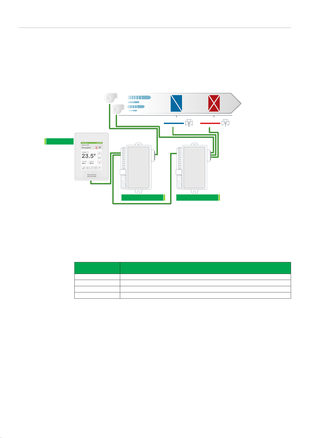
SE8300 as Zone Controllers
This section shows how the SE8300 series Room Controllers are used as Zone Controllers.
SE8300UXBXX HEATING ONLY ANALOG VALVE ACTUATOR, 2 PIPE
35
Airflow Direction
Heating Coil
ANALOG
HEATING VALVE
Configuration
Parameter
Name
Pipe no. 2
Seq. operation Heat only
Control type Analog
Note: Select a user interface that does not display the FAN MODE button
Configuration Settings

36
Schneider Electric | AG-SER83 00-SE8 300-FCU-A4.EN.01.2016.v6 January 2016
SE8300
BO2 - Fan L
1 2 3 4 5 6
1 2 3 4 5 6
RC (24 Vac)
BO4 - Fan H
BO3 - Fan M
C (Common)
Modulating Control
RH
- Analog Heat
BO8 - Aux Heat
7 8 9 10 11 12
7 8 9 10 11 12
UO11
UO12 - Analog Cool
HEATING VALVE
FCU Low-voltage
TERMINAL BLOCK
COMM ON
24 VAC
13 14 15 16 17 18
13 14 15 16 17 18
BACnet +
BACnet -
BACnet REF
UI 16
UI 17
Common
19 20 21 22 23 24
19 20 21 22 23 24
UI 19
UI 20 - RS
Common
UI22 - SS
Sequence of Operation and Wiring
Occupied Mode
During Occupied periods, the occupied heating and cooling
setpoints are used.
Stand-by Mode (only available when PIR motion detector
sensor is used)
When equipped with a PIR (Passive Infrared) accessory
sensor the Controller provides advanced active occupancy
logic, which automatically switches occupancy levels from
Occupied to Stand-by to Unoccupied when no motion is
detected in the room:
• During PIR activated Stand-by periods, Stand-by heating
and cooling setpoints are used
• During PIR activated unoccupied periods, unoccupied-by
heating and cooling setpoints are used.
to demand.
Options
• Wireless adapter modules for BACnet models are
available. (see Appendix B for network wiring).
• Remote wall mounted sensor or return air temperature
sensor can be used instead of internal temperature
sensor of Controller.
• 3 universal inputs can be used and configured for
advanced functionality as required by the application.
• Auxiliary electric reheat can be added if required by
application.
Unoccupied Mode
During unoccupied periods, the unoccupied heating and
cooling setpoints are used.
Occupied Override Mode
The Controller reverts back to Occupied mode as specified
by a configuration timer when a local override is requested at
Controller.
On Call for Heat
The heating valve modulates from closed to open according

Schneider Electric | AG-SER83 00-SE8 300-FCU-A4.EN.01.2016.v6 January 2016
SE8300UXBXX COOLING ONLY ANALOG VALVE ACTUATOR, 2 PIPE
37
Airflow Direction
Cooling Coil
ANALOG
COOLING VALVE
Configuration
Parameter
Configuration Settings
Name
Pipe no. 2
Seq. operation Cool only
Control type Analog
Note: Select a user interface that does not display the FAN MODE button

38
Schneider Electric | AG-SER83 00-SE8 300-FCU-A4.EN.01.2016.v6 January 2016
SE8300
BO2 - Fan L
1 2 3 4 5 6
1 2 3 4 5 6
RC (24 Vac)
BO4 - Fan H
BO3 - Fan M
C (Common)
Modulating Control
RH
- Analog Heat
BO8 - Aux Heat
7 8 9 10 11 12
7 8 9 10 11 12
UO11
UO12 - Analog Cool
COOLING VALVE
0-10 V 24V Com.
24 Vac Transformer
COMM ON
24 VAC
13 14 15 16 17 18
13 14 15 16 17 18
BACnet +
BACnet -
BACnet REF
UI 16
UI 17
Common
19 20 21 22 23 24
19 20 21 22 23 24
UI 19
UI 20 - RS
Common
UI22 - SS
Sequence of Operation and Wiring
Occupied Mode
During Occupied periods, the occupied heating and cooling
setpoints are used.
Stand-by Mode (only available when PIR motion detector
sensor is used)
When equipped with a PIR (Passive Infrared) accessory
sensor the Controller provides advanced active occupancy
logic, which automatically switches occupancy levels from
Occupied to Stand-by to Unoccupied when no motion is
detected in the room:
• During PIR activated Stand-by periods, Stand-by heating
and cooling setpoints are used
• During PIR activated unoccupied periods, unoccupied-by
heating and cooling setpoints are used.
Unoccupied Mode
During unoccupied periods, the unoccupied heating and
cooling setpoints are used.
Occupied Override Mode
The Controller reverts back to Occupied mode as specified
by a configuration timer when a local override is requested at
Controller.
On Call for Heat
The heating valve modulates from closed to open according
to demand.
Options
• Wireless adapter modules for BACnet models are
available. (see Appendix B for network wiring).
• Remote wall mounted sensor or return air temperature
sensor can be used instead of internal temperature
sensor of Controller.
• 3 universal inputs can be used and configured for
advanced functionality as required by the application.
• Auxiliary electric reheat can be added if required by
application.

Schneider Electric | AG-SER83 00-SE8 300-FCU-A4.EN.01.2016.v6 January 2016
SE8300UXBXX HEATING COIL WITH TRI-STATE FLOATING VALVE ACTUATOR AND PWM ELECTRIC
DUCT HEATER
39
Airflow Direction
Heating Coil
TRI-STATE
FLOATING VALVE
On/Off Duct Heater
SSR
SOLID STATE RELAY
(R1810 WITH HEATSINK)
Configuration
Parameter
Name
Fan menu ON-AUTO
Control Type Floating
BO8 Out Time 1 = 10 Second
BO8 AuxOut 0-Heat
Pipe no. 2
Seq. operation Heat-rht
Configuration Settings

40
Schneider Electric | AG-SER83 00-SE8 300-FCU-A4.EN.01.2016.v6 January 2016
SE8300
BO2 - Fan L
1 2 3 4 5 6
1 2 3 4 5 6
RC (24 Vac)
BO4 - Fan H
BO3 - Fan M
C (Common)
Floating & PWM Control
RH
- Close Cool V
BO8 - Aux Heat
UO9
7 8 9 10 11 12
7 8 9 10 11 12
UO12 - Open Heat V
UO10 - Close Heat V
UO11 - Open Cool V
PWM DUCT HEATER
SOLID STATE RELAY
HEATING VALVE
Close Open Com.
24 Vac Transformer
COMM ON
24 VAC
13 14 15 16 17 18
13 14 15 16 17 18
BACnet +
BACnet -
BACnet REF
UI 16
UI 17
Common
19 20 21 22 23 24
19 20 21 22 23 24
UI 19
UI 20 - RS
Common
UI22 - SS
Sequence of Operation and Wiring
Occupied Mode
During Occupied periods, the occupied heating and cooling
setpoints are used.
Stand-by Mode (only available when PIR motion detector
sensor is used)
When equipped with a PIR (Passive Infrared) accessory
sensor the Controller provides advanced active occupancy
logic, which automatically switches occupancy levels from
Occupied to Stand-by to Unoccupied when no motion is
detected in the room:
• During PIR activated Stand-by periods, Stand-by heating
and cooling setpoints are used
• During PIR activated unoccupied periods, unoccupied-by
heating and cooling setpoints are used.
Unoccupied Mode
During unoccupied periods, the unoccupied heating and
cooling setpoints are used.
Occupied Override Mode
The Controller reverts back to Occupied mode as specified
by a configuration timer when a local override is requested at
Controller.
On Call for Heat
The proportional device will act as a first step and modulates
from 0 to 100% capacity. The perimeter heater will operate
as a second step.
Options
• Wireless adapter modules for BACnet models are
available. (see Appendix B for network wiring).
• Remote wall mounted sensor or return air temperature
sensor can be used instead of internal temperature
sensor of Controller.
• 3 universal inputs can be used and configured for
advanced functionality as required by the application.

Schneider Electric | AG-SER83 00-SE8 300-FCU-A4.EN.01.2016.v6 January 2016
SE8300UXBXX HEATING WITH REHEAT, MODULATING DUCT HEATER, ELECTRIC PERIMETER
41
Airflow Direction
Two-stage Duct Heater
R820
SCR
(R1810 WITH HEATSINK)
PERIMETER HEATER
SSR
SOLID STATE RELAY
Configuration
Parameter
Name
Fan menu ON-AUTO
BO8 Out Time 1 = 10 Second
BO8 AuxOut 0-Heat
Pipe no. 2
Seq. operation Heat-rht
Configuration Settings

42
Schneider Electric | AG-SER83 00-SE8 300-FCU-A4.EN.01.2016.v6 January 2016
SE8300
BO2 - Fan L
1 2 3 4 5 6
1 2 3 4 5 6
RC (24 Vac)
BO4 - Fan H
BO3 - Fan M
C (Common)
Mod. & PWM Control
RH
- Close Cool V
BO8 - Aux Heat
UO9
UO11 - Open Cool V
UO12 - Open Heat V
UO10 - Close Heat V
7 8 9 10 11 12
7 8 9 10 11 12
PERMETER HEAT
SOLID STATE RELAY
DUCT HEATER, SRC
0-10 V 24V Com.
24 Vac Transformer
COMM ON
24 VAC
13 14 15 16 17 18
13 14 15 16 17 18
BACnet +
BACnet -
BACnet REF
UI 16
UI 17
Common
19 20 21 22 23 24
19 20 21 22 23 24
UI 19
UI 20 - RS
Common
UI22 - SS
Sequence of Operation and Wiring
Occupied Mode
During Occupied periods, the occupied heating and cooling
setpoints are used.
Stand-by Mode (only available when PIR motion detector
sensor is used)
When equipped with a PIR (Passive Infrared) accessory
sensor the Controller provides advanced active occupancy
logic, which automatically switches occupancy levels from
Occupied to Stand-by to Unoccupied when no motion is
detected in the room:
• During PIR activated Stand-by periods, Stand-by heating
and cooling setpoints are used
• During PIR activated unoccupied periods, unoccupied-by
heating and cooling setpoints are used.
Unoccupied Mode
During unoccupied periods, the unoccupied heating and
cooling setpoints are used.
Occupied Override Mode
The Controller reverts back to Occupied mode as specified
by a configuration timer when a local override is requested at
Controller.
On Call for Heat
The proportional device acts as a first step and modulates
from 0 to 100% capacity. The perimeter heater operates as a
second step.
Options
• Wireless adapter modules for BACnet models are
available. (see Appendix B for network wiring).
• Remote wall mounted sensor or return air temperature
sensor can be used instead of internal temperature
sensor of Controller.
• 3 universal inputs can be used and configured for
advanced functionality as required by the application.

Schneider Electric | AG-SER83 00-SE8 300-FCU-A4.EN.01.2016.v6 January 2016
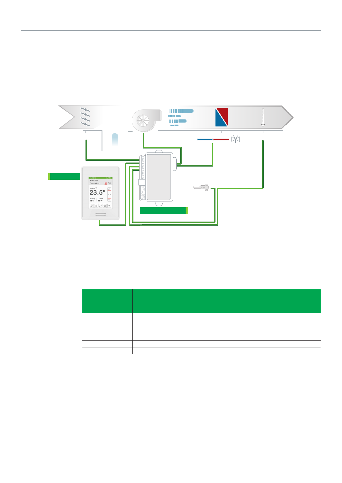
SE8300UXBXX HEATING AND COOLING WITH CHANGEOVER SENSOR AND REHEAT, ANALOG
VALVE ACTUATOR, PWM DUCT HEATER AND WATER SENSOR FOR CHANGEOVER, 2 PIPE
43
Airflow Direction
Cooling / Heating Coil
2 POSITION
COOLING VALVE / HEATING VALVE
CHANGE OVER
SENSOR
On/Off Duct Heater
SSR
SOLID STATE RELAY
(R1810 WITH HEATSINK)
Configuration
Parameter
Name
UI19 COS
Fan menu ON-AUTO
BO8 Out Time 1 = 10 Second
BO8 AuxOut 0-Heat
Pipe no. 2
Seq. operation Cool-rht
Configuration Settings

44
Schneider Electric | AG-SER83 00-SE8 300-FCU-A4.EN.01.2016.v6 January 2016
SE8300
BO2 - Fan L
1 2 3 4 5 6
1 2 3 4 5 6
RC (24 Vac)
BO4 - Fan H
BO3 - Fan M
C (Common)
Mod. & PWM Control
RH
- Close Cool V
BO8 - Aux Heat
UO9
UO11 - Open Cool V
UO10 - Close Heat V
UO12 - Open Heat V
7 8 9 10 11 12
7 8 9 10 11 12
PWM DUCT HEATER
SOLID STATE RELAY
0-10 V 24V Com.
HEATING / COOLING
VALVE
0-10 V 24V Com.
24 Vac Transformer
COMM ON
24 VAC
13 14 15 16 17 18
13 14 15 16 17 18
BACnet +
BACnet -
BACnet REF
UI 16
UI 17
Common
19 20 21 22 23 24
19 20 21 22 23 24
UI 19
UI 20 - RS
Common
UI22 - SS
Sequence of Operation and Wiring
Occupied Mode
During Occupied periods, the occupied heating and cooling
setpoints are used.
Stand-by Mode (only available when PIR motion detector
sensor is used)
When equipped with a PIR (Passive Infrared) accessory
sensor the Controller provides advanced active occupancy
logic, which automatically switches occupancy levels from
Occupied to Stand-by to Unoccupied when no motion is
detected in the room:
• During PIR activated stand-by periods, stand-by heating
and cooling setpoints are used.
• During PIR activated unoccupied periods, unoccupied-by
heating and cooling setpoints are used.
Unoccupied Mode
During unoccupied periods, unoccupied heating and cooling
setpoints are used.
Occupied Override Mode
The Controller reverts back to Occupied mode as specified
by a configuration timer when a local override is requested at
Controller.
CO SENSOR
SCOM
10 k-2
On Call for Heat
If supply water temperature is less than 75°F (23.9°C), the
valve modulates from closed to open according to demand.
If water supply temperature is greater than 77°F (25°C), valve
remains closed.
On Call for Cool
If supply water temperature is higher than 77°F (25°C), valve
modulates from closed to open according to demand. If
water supply temperature is less than 75°F (23.9°C), valve
remains closed. The duct heater operates as a second step.
Options
• Wireless adapter modules for BACnet models are
available. (see Appendix B for network wiring).
• Remote wall mounted sensor or return air temperature
sensor can be used instead of internal temperature
sensor of Controller.
• 3 universal inputs can be used and configured for
advanced functionality as required by the application.

Schneider Electric | AG-SER83 00-SE8 300-FCU-A4.EN.01.2016.v6 January 2016
SE8300UXBXX HEATING AND COOLING WITH CHANGEOVER SENSOR AND REHEAT, TRI-STATE
FLOATING ACTUATOR, PWM DUCT HEATER AND WATER SENSOR FOR CHANGEOVER, 2 PIPE
45
Airflow Direction
Cooling / Heating Coil
COOLING VALVE / HEATING VALVE
CHANGE OVER
SENSOR
TRI-STATE
On/Off Duct Heater
SSR
SOLID STATE RELAY
(R1810 WITH HEATSINK)
Configuration
Parameter
Name
UI19 COS
Fan menu ON-AUTO
Control Type Floating
BO8 Out Time 1 = 10 Second
BO8 AuxOut 0-Heat
Pipe no. 2
Seq. operation Cool-rht
Configuration Settings

46
Schneider Electric | AG-SER83 00-SE8 300-FCU-A4.EN.01.2016.v6 January 2016
SE8300
BO2 - Fan L
1 2 3 4 5 6
1 2 3 4 5 6
RC (24 Vac)
BO4 - Fan H
BO3 - Fan M
C (Common)
Floating & PWM Control
RH
- Close Cool V
BO8 - Aux Heat
UO9
7 8 9 10 11 12
7 8 9 10 11 12
UO12 - Open Heat V
UO11 - Open Cool V
UO10 - Close Heat V
PWM DUCT HEATER
SOLID STATE RELAY
HEATING / COOLING
VALVE
24 Vac Transformer
COMM ON
24 VAC
13 14 15 16 17 18
13 14 15 16 17 18
BACnet +
BACnet -
BACnet REF
UI 16
UI 17
Common
19 20 21 22 23 24
19 20 21 22 23 24
UI 19
UI 20 - RS
Common
UI22 - SS
Sequence of Operation and Wiring
Occupied Mode
During Occupied periods, occupied heating and cooling
setpoints are used.
Stand-by Mode (only available when PIR motion detector
sensor is used)
When equipped with a PIR (Passive Infrared) accessory
sensor the Controller provides advanced active occupancy
logic, which automatically switches occupancy levels from
occupied to stand-by to unoccupied when no motion is
detected in the room:
• During PIR activated stand-by periods, stand-by heating
and cooling setpoints are used.
• During PIR activated unoccupied periods, the
unoccupied-by heating and cooling setpoints are used.
Unoccupied Mode
During Unoccupied periods, unoccupied heating and cooling
setpoints are used.
Occupied Override Mode
The Controller reverts back to Occupied mode as specified
by a configuration timer when a local override is requested at
Controller.
CO SENSOR
SCOM
10 k-2
On Call for Heat
If supply water temperature is less than 75°F (23.9°C), valve
modulates from closed to open according to demand. If
water supply temperature is greater than 77°F (25°C), valve
remains closed.
On Call for Cool
If supply water temperature is higher than 77°F (25°C), valve
modulates from closed to open according to demand. If
water supply temperature is less than 75°F (23.9°C), valve
remains closed. The duct heater operates as a second step.
Options
• Wireless adapter modules for BACnet models are
available. (see Appendix B for network wiring).
• Remote wall mounted sensor or return air temperature
sensor can be used instead of internal temperature
sensor of Controller.
• 3 universal inputs can be used and configured for
advanced functionality as required by the application.

Schneider Electric | AG-SER83 00-SE8 300-FCU-A4.EN.01.2016.v6 January 2016
SE8300UXBXX HEATING AND COOLING WITH CHANGEOVER SENSOR AND REHEAT, ANALOG 0-10
VDC AIR DAMPER ACTUATOR, PWM DUCT HEATER AND AIR SENSOR FOR CHANGEOVER, 2 PIPE
47
Airflow Direction
CHANGE OVER
SENSOR
Analog Damper
DAMPER
On/Off Duct Heater
SSR
SOLID STATE RELAY
(R1810 WITH HEATSINK)
Configuration
Parameter
Configuration Settings
Name
UI19 COS
Fan menu ON-AUTO
BO8 Out Time 1 = 10 Second
BO8 AuxOut 0-Heat
Prop. band Default value 3.0. Range = 3.0 to 10.
Pipe no. 2
Seq. operation Cool-rht

48
Schneider Electric | AG-SER83 00-SE8 300-FCU-A4.EN.01.2016.v6 January 2016
SE8300
BO2 - Fan L
1 2 3 4 5 6
1 2 3 4 5 6
RC (24 Vac)
BO4 - Fan H
BO3 - Fan M
C (Common)
Mod. & On / Off Control
RH
- Close Cool V
BO8 - Aux Heat
UO9
UO11 - Open Cool V
UO10 - Close Heat V
UO12 - Open Heat V
7 8 9 10 11 12
7 8 9 10 11 12
PWM DUCT HEATER
SOLID STATE RELAY
ZONE DAMPER ACTUATOR
0-10 V 24V Com.
24 Vac Transformer
COMM ON
24 VAC
13 14 15 16 17 18
13 14 15 16 17 18
BACnet +
BACnet -
BACnet REF
UI 16
UI 17
19 20 21 22 23 24
19 20 21 22 23 24
UI 19
UI 20 - RS
Common
Common
UI22 - SS
Sequence of Operation and Wiring
Occupied Mode
During Occupied periods, occupied heating and cooling
setpoints are used.
Stand-by Mode (only available when PIR motion detector
sensor is used)
When equipped with a PIR (Passive Infrared) accessory
sensor the Controller provides advanced active occupancy
logic, which automatically switches occupancy levels from
occupied to stand-by to unoccupied when no motion is
detected in the room:
• During PIR activated stand-by periods, stand-by heating
and cooling setpoints are used.
• During PIR activated unoccupied periods, the
unoccupied-by heating and cooling setpoints are used.
Unoccupied Mode
During unoccupied periods, unoccupied heating and cooling
setpoints are used.
Local Override
The controller reverts back to Occupied mode as specified
by a configuration timer when a local override is requested
at Controller.
CO SENSOR
SCOM
10 k-2
On Call for Heat
If supply water temperature is higher than 77°F (25°C), valve
modulates from closed to open according to demand. If
water supply temperature is less than 75°F (23.9°C), valve
remains closed. The duct heater operates as a second step.
On Call for Cool
If supply air temperature is less than 75°F (23.9°C), damper
modulates from closed to open according to demand.
If water supply temperature is greater than 77°F (25°C),
damper remains closed.
Options
• Wireless adapter modules for BACnet models are
available. (see Appendix B for network wiring).
• Remote wall mounted sensor or return air temperature
sensor can be used instead of internal temperature
sensor of Controller.
• 3 universal inputs can be used and configured for
advanced functionality as required by the application.

Schneider Electric | AG-SER83 00-SE8 300-FCU-A4.EN.01.2016.v6 January 2016
SE8300UXBXX HEATING AND COOLING WITH CHANGEOVER SENSOR AND REHEAT, FLOATING AIR
DAMPER ACTUATOR, PWM DUCT HEATER AND SUPPLY AIR SENSOR FOR CHANGEOVER, 2 PIPE
49
Airflow Direction
CHANGE OVER
SENSOR
Floating Damper
DAMPER
On/Off Duct Heater
SSR
SOLID STATE RELAY
(R1810 WITH HEATSINK)
Configuration
Parameter
Name
UI19 COS
Fan menu ON-AUTO
Control Type Floating
BO8 Out Time 1 = 10 Second
BO8 AuxOut 0-Heat
Pipe no. 2
Seq. operation Cool-rht
Configuration Settings

50
Schneider Electric | AG-SER83 00-SE8 300-FCU-A4.EN.01.2016.v6 January 2016
SE8300
BO2 - Fan L
1 2 3 4 5 6
1 2 3 4 5 6
RC (24 Vac)
BO4 - Fan H
BO3 - Fan M
C (Common)
Floating & PWM Control
RH
- Close Cool V
BO8 - Aux Heat
UO9
7 8 9 10 11 12
7 8 9 10 11 12
UO12 - Open Heat V
UO11 - Open Cool V
UO10 - Close Heat V
PWM DUCT HEATER
SOLID STATE RELAY
ZONE DAMPER ACTUATOR
Close Open Com.
24 Vac Transformer
COMM ON
24 VAC
13 14 15 16 17 18
13 14 15 16 17 18
BACnet +
BACnet -
BACnet REF
UI 16
UI 17
Common
19 20 21 22 23 24
19 20 21 22 23 24
UI 19
UI 20 - RS
Common
UI22 - SS
Sequence of Operation and Wiring
Occupied Mode
During Occupied periods, occupied heating and cooling
setpoints are used.
Stand-by Mode (only available when PIR motion detector
sensor is used)
When equipped with a PIR (Passive Infrared) accessory
sensor the Controller provides advanced active occupancy
logic, which automatically switches occupancy levels from
occupied to stand-by to unoccupied when no motion is
detected in the room:
• During PIR activated stand-by periods, stand-by heating
and cooling setpoints are used.
• During PIR activated unoccupied periods, the
unoccupied-by heating and cooling setpoints are used.
Unoccupied Mode
During unoccupied periods, unoccupied heating and cooling
setpoints are used.
Local Override
The Controller reverts back to the occupied mode as
specified by a configuration timer when a local override is
requested at Controller.
CO SENSOR
SCOM
10 k-2
On Call for Heat
If supply water temperature is higher than 77°F (25°C), valve
modulates from closed to open according to demand. If
water supply temperature is less than 75°F (23.9°C), valve
remains closed. The duct heater operates as a second step.
On Call for Cool
If supply air temperature is less than 75°F (23.9°C), damper
modulates from closed to open according to demand.
If water supply temperature is greater than 77°F (25°C),
damper remains closed.
Options
• Wireless adapter modules for BACnet models are
available. (see Appendix B for network wiring).
• Remote wall mounted sensor or return air temperature
sensor can be used instead of internal temperature
sensor of Controller.
• 3 universal inputs can be used and configured for
advanced functionality as required by the application.

Schneider Electric | AG-SER83 00-SE8 300-FCU-A4.EN.01.2016.v6 January 2016
SE8300UXBXX COOLING AND REHEAT, ANALOG 0-10 VDC AIR DAMPER ACTUATOR, ANALOG DUCT
HEATER AND ELECTRIC PERIMETER
51
Airflow Direction
Modulating Damper
DAMPER
Modulating Duct Heater
PERIMETER HEATER
SSR
SOLID STATE RELAY
(R1810 WITH HEATSINK)
Configuration
Parameter
Name
Fan menu ON-AUTO
BO8 Out Time 1 = 10 Second
BO8 AuxOut 0-Heat
Pipe no. 4
Seq. operation Cl/ht-rht
Configuration Settings

52
Schneider Electric | AG-SER83 00-SE8 300-FCU-A4.EN.01.2016.v6 January 2016
SE8300
BO2 - Fan L
1 2 3 4 5 6
1 2 3 4 5 6
RC (24 Vac)
BO4 - Fan H
BO3 - Fan M
C (Common)
Modulating & PWM Control
RH
- Close Cool V
BO8 - Aux Heat
UO9
UO11 - Open Cool V
UO12 - Open Heat V
UO10 - Close Heat V
7 8 9 10 11 12
7 8 9 10 11 12
DUCT HEATER, SRC
0-10 V 24V Com.
ZONE DAMPER
COOLING ONLY
ACTUATOR
0-10 V 24V Com.
FCU Low-voltage
TERMINAL BLOCK
COMM ON
24 VAC
13 14 15 16 17 18
13 14 15 16 17 18
BACnet +
BACnet -
BACnet REF
UI 16
UI 17
Common
19 20 21 22 23 24
19 20 21 22 23 24
UI 19
UI 20 - RS
Common
UI22 - SS
Sequence of Operation and Wiring
Occupied Mode
During Occupied periods, occupied heating and cooling
setpoints are used.
Stand-by Mode (only available when PIR motion detector
sensor is used)
When equipped with a PIR (Passive Infrared) accessory
sensor the Controller provides advanced active occupancy
logic, which automatically switches occupancy levels from
occupied to stand-by to unoccupied when no motion is
detected in the room:
• During PIR activated stand-by periods, stand-by heating
and cooling setpoints are used.
• During PIR activated unoccupied periods, the
unoccupied-by heating and cooling setpoints are used.
Unoccupied Mode
During unoccupied periods, unoccupied heating and cooling
setpoints are used.
Local Override
The Controller reverts back to Occupied mode as specified
by a configuration timer when a local override is requested
at Controller.
On Call for Heat
The damper remains closed. The proportional heater acts
as a first step and modulate from 0 to 100% capacity. The
perimeter heater operates as a second step.
On Call for Cool
The damper modulates from closed to open according to
demand.
Options
• Wireless adapter modules for BACnet models are
available. (see Appendix B for network wiring).
• Remote wall mounted sensor or return air temperature
sensor can be used instead of internal temperature
sensor of Controller.
• 3 universal inputs can be used and configured for
advanced functionality as required by the application.

Schneider Electric | AG-SER83 00-SE8 300-FCU-A4.EN.01.2016.v6 January 2016
SE8300 Mixed-voltage Applications
Applications in this section make use of the SC1300 and SC2300 mixed-voltage relays.
SE8350UXBXX AND SC1300 120 VDC RELAY HEATING/COOLING 4-PIPE FAN COIL UNIT WITH HIGH
VOLTAGE 3-SPEED FAN, AND 0-10 VDC ANALOG VALVES AND DEHUMIDIFICATION SEQUENCE FOR
LOW VOLTAGE
53
High Voltage Fan
SE8300
Airflow Direction
Cooling Coil
ANALOG
COOLING VALVE
Refer to Schneider Electric Catalog for valves and
actuators
Power supply
120 vac
Heating Coil
ANALOG
HEATING VALVE
SC1300
Configuration
Parameter
Name
Fan menu L-M-H-A
Pipe no. 4
Seq. operation Cool / Heat
Configuration Settings

54
Schneider Electric | AG-SER83 00-SE8 300-FCU-A4.EN.01.2016.v6 January 2016
1 2 3 4 5 6
13 14 15 16 17 18
7 8 9 10 11 12
19 20 21 22 23 24
1 2 3 4 5 6
13 14 15 16 17 18
7 8 9 10 11 12
19 20 21 22 23 24
SE8300
BO2 - Fan L
BO3 - Fan M
BO4 - Fan H
RC (24 Vac)
C (Common)
BACnet
+
BACnet -
BACnet REF
UI 16 - BI1
UI 17 - BI2
SCom
UI 19 - UI13
UI 20 - RS
SCom
UI22 - SS
Mix Voltage 120 volts
SC1300
RH
BO8 - Aux Heat
UO9
- NC Cool V
UO10 - NC Heat V
UO11 - Analog Heat
UO12 - Analog Cool
FAN HI
FAN MED
FAN LO
COMM ON
High Voltage Fan
Power supply
120 Vac
COOLING VALVE
0-10v 24v Com.
HEATING VALVE
0-10v 24v Com.
Sequence of Operation and Wiring
Occupied Mode
Setpoints revert to those defined by occupied cooling
and heating. The changeover sensor sends supply air
temperature to controller.
Stand-by Mode (only available when PIR motion detector
sensor is used)
Setpoints revert to those defined by stand-by cooling and
heating.
Unoccupied Mode
Setpoints revert to those defined by unoccupied heating and
cooling.
Occupied Override Mode
System reverts to occupied mode for duration determined by
“ToccTime” parameter.
On Call for Cool
Cooling valve opens to maintain room temperature. Heating
valve closes. Dehumidification enabled.
On Call for Heat
On Demand for Dehumidification
Dehumidification is achieved via cooling coil using heating
coil for reheat if necessary.
Dehumidification only allowed in COOL mode, or if cooling is
enabled in AUTO mode.
Dehumidification disabled if room temperature falls below
low ambient lockout temperature, which is cooling setpoint
minus configuration defined deadband value.
Reheat disabled if cooling demand reaches 100%.
Options
• Wireless adapter modules for BACnet models are
available. (see Appendix B for network wiring).
• Remote wall mount or duct sensor ready.
• Can be configured for 2-pipe systems.
• 3 universal inputs can be used and configured for
advanced functionality as required by the application.
• Universal input can be configured for changeover sensor.
Heating valve opens to maintain room temperature. Cooling
valve closes. Dehumidification disabled.

Schneider Electric | AG-SER83 00-SE8 300-FCU-A4.EN.01.2016.v6 January 2016
SE8350UXBXX AND SC2300 240 VDC RELAY HEATING/COOLING 4-PIPE FAN COIL UNIT WITH HIGH
VOLTAGE 3-SPEED FAN, AND 0-10 VDC ANALOG VALVES AND DEHUMIDIFICATION SEQUENCE FOR
LOW VOLTAGE
55
High Voltage Fan
SE8300
Airflow Direction
Cooling Coil
ANALOG
COOLING VALVE
Heating Coil
ANALOG
HEATING VALVE
SC2300
Power supply
240 vac
Refer to Schneider Electric Catalog for valves and
actuators
Configuration
Parameter
Name
Fan menu L-M-H-A
Pipe no. 4
Seq. operation Cool / Heat
Configuration Settings

56
Schneider Electric | AG-SER83 00-SE8 300-FCU-A4.EN.01.2016.v6 January 2016
1 2 3 4 5 6
13 14 15 16 17 18
7 8 9 10 11 12
19 20 21 22 23 24
1 2 3 4 5 6
13 14 15 16 17 18
7 8 9 10 11 12
19 20 21 22 23 24
SE8300
BO2 - Fan L
BO3 - Fan M
BO4 - Fan H
RC (24 Vac)
C (Common)
BACnet
+
BACnet -
BACnet REF
UI 16 - BI1
UI 17 - BI2
SCom
UI 19 - UI13
UI 20 - RS
SCom
UI22 - SS
Mix Voltage 240 volts
SC2300
RH
BO8 - Aux Heat
UO9
- NC Cool V
UO10 - NC Heat V
UO11 - Analog Heat
UO12 - Analog Cool
FAN HI
FAN MED
FAN LO
COMM ON
High Voltage Fan
Power supply
240 Vac
COOLING VALVE
0-10v 24v Com.
HEATING VALVE
0-10v 24v Com.
Sequence of Operation and Wiring
Occupied Mode
Setpoints revert to those defined by occupied cooling
and heating. The changeover sensor sends supply air
temperature to controller.
Stand-by Mode (only available when PIR motion detector
sensor is used)
Setpoints revert to those defined by stand-by cooling and
heating.
Unoccupied Mode
Setpoints revert to those defined by unoccupied heating and
cooling.
Occupied Override Mode
System reverts to occupied mode for duration determined by
“ToccTime” parameter.
On Call for Cool
Cooling valve opens to maintain room temperature. Heating
valve closes. Dehumidification enabled.
On Call for Heat
On Demand for Dehumidification
Dehumidification is achieved via cooling coil using heating
coil for reheat if necessary.
Dehumidification only allowed in COOL mode, or if cooling is
enabled in AUTO mode.
Dehumidification disabled if room temperature falls below
low ambient lockout temperature, which is cooling setpoint
minus configuration defined deadband value.
Reheat disabled if cooling demand reaches 100%.
Options
• Wireless adapter modules for BACnet models are
available. (see Appendix B for network wiring).
• Remote wall mount or duct sensor ready.
• Can be configured for 2-pipe systems.
• 3 universal inputs can be used and configured for
advanced functionality as required by the application.
• Universal input can be configured for changeover sensor.
Heating valve opens to maintain room temperature. Cooling
valve closes. Dehumidification disabled.

Schneider Electric | AG-SER83 00-SE8 300-FCU-A4.EN.01.2016.v6 January 2016
SE8350UXBXX AND SC1300 120 VDC RELAY HEATING/COOLING 4-PIPE FAN COIL UNIT WITH HIGH
VOLTAGE 3-SPEED FAN, TRI-STATE FLOATING VALVES AND DEHUMIDIFICATION SEQUENCE FOR
LOW VOLTAGE
57
High Voltage Fan
SE8300
Airflow Direction
Cooling Coil
TRI-STATE
FLOATING VALVE
Heating Coil
TRI-STATE
FLOATING VALVE
SC1300
Power supply
120 vac
Refer to Schneider Electric Catalog for valves and
actuators
Configuration
Parameter
Name
Fan menu L-M-H-A
Control Type Floating
Pipe no. 4
Seq. operation Cool / Heat
Configuration Settings

58
Schneider Electric | AG-SER83 00-SE8 300-FCU-A4.EN.01.2016.v6 January 2016
1 2 3 4 5 6
13 14 15 16 17 18
7 8 9 10 11 12
19 20 21 22 23 24
1 2 3 4 5 6
13 14 15 16 17 18
7 8 9 10 11 12
19 20 21 22 23 24
SE8300
BO2 - Fan L
BO3 - Fan M
BO4 - Fan H
RC (24 Vac)
C (Common)
BACnet
+
BACnet -
BACnet REF
UI 16 - BI1
UI 17 - BI2
SCom
UI 19 - UI13
UI 20 - RS
SCom
UI22 - SS
Floating Control Mix Voltage
SC1300
RH
BO8 - Aux Heat
UO9
- NC Cool V
UO10 - NC Heat V
UO11 - Analog Heat
UO12 - Analog Cool
FAN HI
FAN MED
FAN LO
COMM ON
High Voltage Fan
Power supply
120 Vac
COOLING VALVE
Open Close Com.
HEATING VALVE
Open Close Com.
Sequence of Operation and Wiring
Occupied Mode
Setpoints revert to those defined by occupied cooling and
heating.
Stand-by Mode (only available when PIR motion detector
sensor is used)
Setpoints revert to those defined by stand-by cooling and
heating.
Unoccupied Mode
On Demand for Dehumidification
Dehumidification is achieved via cooling coil using heating
coil for reheat if necessary.
Dehumidification is only allowed in COOL mode, or if cooling
is enabled in AUTO mode.
Dehumidification is disabled if room temperature falls
below low ambient lockout temperature, which is the cooling
setpoint minus the configuration defined deadband value.
Reheat disabled if cooling demand reaches 100%.
Setpoints revert to those defined by unoccupied heating and
cooling.
Occupied Override Mode
System reverts to occupied mode for duration determined by
“ToccTime” parameter.
On Call for Cool
Cooling valve opens to maintain room temperature. Heating
valve closes.
On Call for Heat
Heating valve opens to maintain room temperature. Cooling
Options
• Wireless adapter modules for BACnet models are
available. (see Appendix B for network wiring).
• Remote wall mount or duct sensor ready.
• Can be configured for 2-pipe systems with changeover.
• 3 universal inputs can be used and configured for
advanced functionality as required by the application.
• Universal input can be configured for changeover sensor.
valve closes.

59
Schneider Electric | AG-SER83 00-SE8 300-FCU-A4.EN.01.2016.v6 January 2016
SE8350UXBXX AND SC2300 240 VDC RELAY HEATING/COOLING 4-PIPE FAN COIL UNIT WITH HIGH
VOLTAGE 3-SPEED FAN, TRI-STATE FLOATING VALVES AND DEHUMIDIFICATION SEQUENCE FOR LOW
VOLTAGE
High Voltage Fan
SE8300
Airflow Direction
Cooling Coil
TRI-STATE
FLOATING VALVE
Heating Coil
TRI-STATE
FLOATING VALVE
SC2300
Power supply
240 vac
Refer to Schneider Electric Catalog for valves and
actuators
Configuration
Parameter
Name
Fan menu L-M-H-A
Control Type Floating
Pipe no. 4
Seq. operation Cool / Heat
Configuration Settings

60
Schneider Electric | AG-SER83 00-SE8 300-FCU-A4.EN.01.2016.v6 January 2016
1 2 3 4 5 6
13 14 15 16 17 18
7 8 9 10 11 12
19 20 21 22 23 24
1 2 3 4 5 6
13 14 15 16 17 18
7 8 9 10 11 12
19 20 21 22 23 24
SE8300
BO2 - Fan L
BO3 - Fan M
BO4 - Fan H
RC (24 Vac)
C (Common)
BACnet
+
BACnet -
BACnet REF
UI 16 - BI1
UI 17 - BI2
SCom
UI 19 - UI13
UI 20 - RS
SCom
UI22 - SS
Floating Control Mix Voltage
SC2300
RH
BO8 - Aux Heat
UO9
- NC Cool V
UO10 - NC Heat V
UO11 - Analog Heat
UO12 - Analog Cool
FAN HI
FAN MED
FAN LO
COMM ON
High Voltage Fan
Power supply
240 Vac
COOLING VALVE
Open Close Com.
HEATING VALVE
Open Close Com.
Sequence of Operation and Wiring
Occupied Mode
Setpoints revert to those defined by occupied cooling and
heating.
Stand-by Mode (only available when PIR motion detector
sensor is used)
Setpoints revert to those defined by stand-by cooling and
heating.
Unoccupied Mode
On Demand for Dehumidification
Dehumidification is achieved via cooling coil using heating
coil for reheat if necessary.
Dehumidification is only allowed in COOL mode, or if cooling
is enabled in AUTO mode.
Dehumidification is disabled if room temperature falls
below low ambient lockout temperature, which is the cooling
setpoint minus the configuration defined deadband value.
Reheat disabled if cooling demand reaches 100%.
Setpoints revert to those defined by unoccupied heating and
cooling.
Occupied Override Mode
System reverts to occupied mode for duration determined by
“ToccTime” parameter.
On Call for Cool
Cooling valve opens to maintain room temperature. Heating
valve closes.
On Call for Heat
Heating valve opens to maintain room temperature. Cooling
Options
• Wireless adapter modules for BACnet models are
available. (see Appendix B for network wiring).
• Remote wall mount or duct sensor ready.
• Can be configured for 2-pipe systems with changeover.
• 3 universal inputs can be used and configured for
advanced functionality as required by the application.
• Universal input can be configured for changeover sensor.
valve closes.

Schneider Electric | AG-SER83 00-SE8 300-FCU-A4.EN.01.2016.v6 January 2016
APPENDIX A - PASSIVE INFRA-RED SENSOR
Sequence of Operation
Initially, the Room Controller is in Stand-by mode and Stand-by setpoints are used. When the Passive Infra-Red (PIR) sensor
detects motion, the Occupancy status switches to Occupied and the Stand-By Time timer is reset. The Occupied setpoints are
used for this operation. If no motion is detected in the room for the entire Stand-By Time duration (adjustable parameter), the
room switches to Stand-by mode and Stand-by setpoints are used. While in Stand-by mode, if no motion is detected for the entire
Unoccupied Time period (adjustable parameter), the room switches to Unoccupied mode and uses its Unoccupied setpoints.
While in Stand-By or Unoccupied mode, any motion switches the room back to Occupied mode.
PIR ranges measure 20 feet (6 meters) at 140° and 13 feet (4.5 meters) minimum between 15° to 30° laterally. A typical
installation height of approximately 5 feet (1.5 meters) is considered in these measurements.
The below illustrates the resolution.
O
140
Side view
O
60
O
15
O
O
25
O
25
15
61
(6 m) (5 m) (4 m)
O
15
Top view
O
15
13 ft20 ft 16 ft 13 ft
20 ft16 ft
(6 m)(5 m)(4 m)
Fresnel lens beam and detection field
Forward movement
140
Lateral movement
O
20 ft (6 m)
20 ft (6 m)
20 ft (6 m)
Top view

62
Schneider Electric | AG-SER83 00-SE8 300-FCU-A4.EN.01.2016.v6 January 2016
Energy Savings
Typical Sa vings of 10-30%
85
80
75
70
65
60
55
50
45
40
35
30
25
Ener gy U sage (KWh)
20
15
10
5
0
0 2 4 6 8 10 12 14 16 18 20 22 24
Time of Day (EST)
Typical Consumption PIR Therm ostat Consumption Savings
50%
40%
Saving Percentage
30%
20%
10%
0%

Schneider Electric | AG-SER83 00-SE8 300-FCU-A4.EN.01.2016.v6 January 2016
Deployment
It is recommended to install the Room Controller as close to a door as possible (but not so as to be blocked by the door), or in an
area with high occupant movement.
Ideally the Room Controller should be installed 5 feet (1.5 meters) above the floor surface to ensure maximum detection range is
achieved. As well, Room Controller placement should ensure the occupant crosses the lens beam in a perpendicular path within
the prescribed detection zone.
Example of Recommended Deployment
The below shows Room Controllers installed in ideal locations for two rooms.
The examination room shows one Room Controller installed adjacent to the door. In this area of the room, occupant traffic is high
and ensures the occupant will almost always cross the PIR detection path laterally and within the detection range.
The waiting room shows one Room Controller installed beside a door in the middle of the room. As shown in the diagram below,
occupant traffic is high in several areas of the room including the entrance, waiting room, access to the door and activity around
the
reception desk. Moreover, for each case aforementioned, occupant movement almost always moves lateral to the PIR, which
ensures detection by the PIR, as well as respecting the PIR detection range of 20 feet (6 meters) at 140°, and 16 feet (5 meters)
between 15° to 30° laterally.
63
Recommended Installation

64
Schneider Electric | AG-SER83 00-SE8 300-FCU-A4.EN.01.2016.v6 January 2016
Example of Non-Recommended Deployment
The below shows four Room Controllers (two for each room) installed in non-ideal locations for the two rooms.
The examination room shows one Room Controller installed in a low traffic area near the door, and a second Room Controller
installed on the wall directly opposite the door. For the Room Controller installed in the corner wall near the door, the PIR could be
blocked by the opened door, thereby restricting PIR detection. For the second Room Controller installed opposite the door, the
PIR detection could fall outside the specified detection zone, while at the same time most occupant movement may not respect
lateral crossing patterns for PIR detection.
The waiting room shows one Room Controller installed near the entrance, and a second Room Controller installed beside the
reception area. For the Room Controller installed at the entrance, the opening/closing of the door creates high probability the PIR
would get blocked, and therefore, occupancy going undetected. For the Room Controller installed beside the reception area, occupant traffic could fall outside the detection zone, while the receptionist would often be below the 5 foot recommended installation height for the Room Controller.
Non-Recommended Installation

Schneider Electric | AG-SER83 00-SE8 300-FCU-A4.EN.01.2016.v6 January 2016
Setpoints
e
Stand-by timer reset
Unoccupied timer reset
APPENDIX B - OPTIONAL NETWORK SET-UP
65
BACnet® Communication Wiring
BACnet
thermostat
1
BACnet
thermostat
2
BACnet
thermostat
3
Notes:
• Wiring should be daisy chained
• Always respect polarity
• If using 2 conductors and shielded wires,
connect shield of each feed together on back
of Controller
• Only ground shield at one location. Do not
connect shield to reference terminal
re
re
re
+
-
f
+
-
f
+
-
f
Wireless Communication
No communication wires required
APPENDIX C - SCHEMATIC OF CONTROLLERS OCCUPANCY SEQUENCE OF OPERATION
26.5°C
Unoccupied cool
Stand-by cool
Occupied cool
Occupied heat
Stand-by heat
noccupied heat
Deadband
Movement detected
-
24.5°C
76°F
22°C
72°F
70°F
21°C 21°C
Stand-by
time
Into Stand-by mode
-
Deadband
66°F
19°C
Unoccupied
time
Into Unoccupied
mode
80°F
Deadband
62°F
16.5°C
Next movement
22°C
72°F
70°F
detected
Tim

66
Schneider Electric | AG-SER83 00-SE8 300-FCU-A4.EN.01.2016.v6 January 2016
APPENDIX D - SER8300 CONTROLLER AND SC3000 RELAY PACK
Product Overview
The SER8300 Fan Coil Controller offers a new cost-effective solution for upgrading line-voltage fan
coil unit thermostats. The SER8300 terminal Equipment Fan Coil Unit Controllers are available as
BACnet
No previous building automation training is required for installation and commissioning process,
and installation can be completed in approximately fifteen minutes.
The SC3000 Series Line Voltage Switching Transformer Relay Pack Controllers are designed for
silent control of typical high voltage fan coil device loads (90 - 277 VAC multi-voltages). It uses
advanced microprocessor-based circuitry with a built-in transformer that eliminates all typical
required peripheral components when automating a Fan Coil unit with traditional building
automation systems.
The SC3000 Series Line Voltage Switching Transformer Relay Pack(s) operate as slave unit(s)
under the control of a single master SER83XX Terminal Equipment Controller.
A single SER83XX Terminal Equipment Controller can control up to 10 x SC3000 Series Relay
Packs as they are line-powered units.
The unit locally contains all relay outputs for fan switching and valve control, and models are also
available for extra monitoring/control inputs of the Fan Coil Units.
®
MSTP or wireless ZigBee® Pro networked models.
Typical Fan Coil Unit Set-up
1
Tx/Rx
2
7 Vdc
Power
Com
3
Supply
SC3404E5045
4
RUI 1
5
Low Voltage Connections
to SER8300 Controller
SCom
6
RBI 2
7
SS
8
RS
9
Heat -
10
Heat +
90-277 Vac - 50/60 Hz
1/2HP + 5A Max Comb. or
13A+ 5A Max Comb
Amb. Temp. 50oC
1/2 HP
or 13A
Max
5A
Max
WHITE
BLACK
FAN
RED
LOW
FAN
BLUE
MED
FAN
BROWN
HIGH
YELLOW
COOL
Electrical
Cabinet
1
Tx/Rx
2
7 Vdc
Power
Com
3
Supply
SC3404E5045
4
RUI 1
xxx-xxxx-xx
SCom
5
WHITE
6
RBI 2
90-277 Vac - 50/60 Hz
1/2HP + 5A Max Comb. or
13A+ 5A Max Comb
7
SS
Amb. Temp. 50oC
BLACK
8
RS
FAN
RED
LOW
1/2 HP
9
Heat -
FAN
or 13A
BLUE
MED
Max
10
Heat +
FAN
BROWN
HIGH
5A
YELLOW
COOL
Max
H C
C C
Daisy Chained
Topology
Mixed Daisy Chained
and Star Topology
Star Topology

67
Schneider Electric | AG-SER83 00-SE8 300-FCU-A4.EN.01.2016.v6 January 2016
APPENDIX E - SED SERIES FOR WIRELESS DOOR AND WINDOW SWITCH
®
Wireless ZigBee
Wireless door switches used with an onboard or remote PIR sensor provide advanced local occupancy routines allowing for
increased energy savings during occupied hours without sacrificing occupant comfort. Wireless window switches are used
to monitor exterior windows or patio/balcony doors when opened to prevent unnecessary energy consumption.
Pro Motion Sensors and Door/Window Switch
Room Controllers with SED Series ZigBee
®
Pro wireless switches can be used in stand-alone mode, or with integration to
a central management system, to allow for advanced functions such as central reservation and occupancy functions.
Up to twenty SED-WIN or SED-DOR wireless switches can be used with a SER8300 or SE8300 Room Controller
Up to ten different ZigBee motion sensors and switches (SED-WMS, SED-CMS, or SED-WDS) can be used with a SER8300
or SE8300 Room Controller. Note that if a ZigBee wireless window switch is used, the SE8300 Room Controller cannot also
use a remote PIR motion sensor, whether wired or wireless. Using one or more wireless remote PIR motion sensors means
that a wired PIR motion sensor cannot be used, and vice versa.
The SED Series sensors are factory delivered with batteries and are ready to be installed, configured, and used right out of
the box. Due to the extremely small current consumption of the sensors, the expected battery life is approximately 10 years,
which is equivalent to the battery shelf life.
No tools are required for commissioning or servicing the ZigBee devices. A simple interface on the devices with an onboard LED and hidden switch provides all required functions for local interaction. The SE8300 user interface has screens
used to pair and configure ZigBee devices (SED-WMS, SED-CMS, or SED-WDS only). Local information for battery life and
connectivity (heartbeat) are also displayed through the ZigBee
®
Pro wireless network.
For more information about using the SED-WIN and SED-DOR switches, consult the SED-WIN / SED-DOR Wireless Door
and Window Switch Installation Guide.For more information about using the SED-WDS, SED-WMS and SED-CMS wireless
switches and sensors, consult the Pairing SE8000 Series Room Controllers with ZigBee Sensors Installation Guide and
Procedure.
Model Selection
Window Switch Door Switch
Door switch SED-DOR-P-5045
Window switch SED-WIN-P-5045
Door/window switch SED-WDS-P-5045
Wall mounted
motion sensor
Ceiling mounted
motion sensor
SED-WMS-P-5045
SED-CMS-P-5045

68
Schneider Electric | AG-SER83 00-SE8 300-FCU-A4.EN.01.2016.v6 January 2016
SED-CMS
LED
SED-WMS
Hidden
switch
LED
Hidden
switch
LED
SED-WIN
SED-DOR
SED-WDS
LED
Hidden
switch
Hidden
switch
APPENDIX F: TERMINAL CORRESPONDENCE
The terminals of an SE8300 are identified differently and have a wider range of possible functions compared to those of any of
the SE7000 series Room Controllers. Nonetheless, there is a direct correspondence of functions between the terminals of the
SE7000 series and the SE8300 series. Consult the table below to verify the appropriate terminal when replacing a SE7000 Room
Controller with a SE8300 Room Controller.
SE7000 SE8300
Terminal name Terminal ID Terminal name Terminal ID
Binary Input 1 BI1 Universal Input 16 UI16
Binary Input 2 BI2 Universal Input 17 UI17
Universal Input 3 UI3 Universal Input 19 UI19
Sensor Common Scom Terminal 18 Common COM
Remote Sensor RS Universal Input 20 UI20 - RS
Sensor Common Scom Terminal 21 Common COM
Mix/Supply Sensor MS Universal Input 22 UI22 - SS
 Loading...