

SE8300 User Interface Guide
Commercial and Hotel/Lodging HVAC Fan Coil Applications
Version 8
2
Schneider Electric | UI-SE8 300 -HMI- A4.EN.01.2017.v8 January 2017
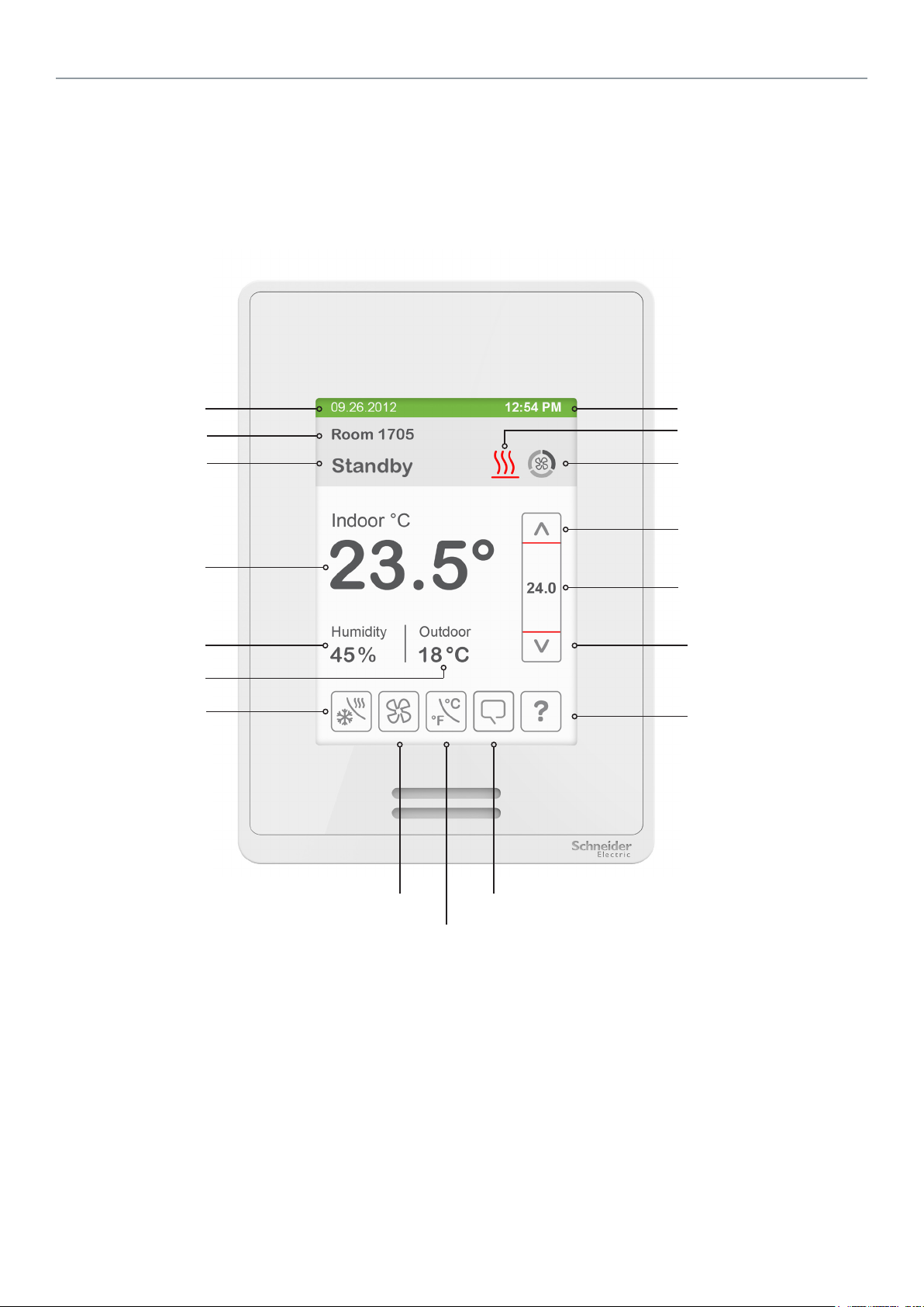
HMI Display
The below shows a typical user interface for the hospitality industry. The User HMI is congurable and allows display functions
such as Date, Time, Humidity, Outdoor Temperature, and Setpoint to be enabled or disabled by setting various parameters.
Short Network
Date
Message
Occupancy Status
Indoor Temperature
Indoor Humidity
Outdoor Temperature
System Mode
Time
System Status
Fan Status
Up Arrow
Increase Temperature Setpoint
Actual Setpoint
Down Arrow
Decrease Temperature
Setpoint
Help
Fan Mode
Temperature Units
Language Selection
General Notes
1. When any change is made to a parameter, the value is automatically saved in memory when the next
parameter is selected or another page is opened.
2. Arrows auto-increment/decrement at higher speed when holding button for more than 2.5 seconds.
3. All objects related to humidity do not display on HMI when Controller is ordered without built-in humidity sensor.
Schneider Electric | UI-SE8 300 -HMI- A4.EN.01.2017.v8 January 2017
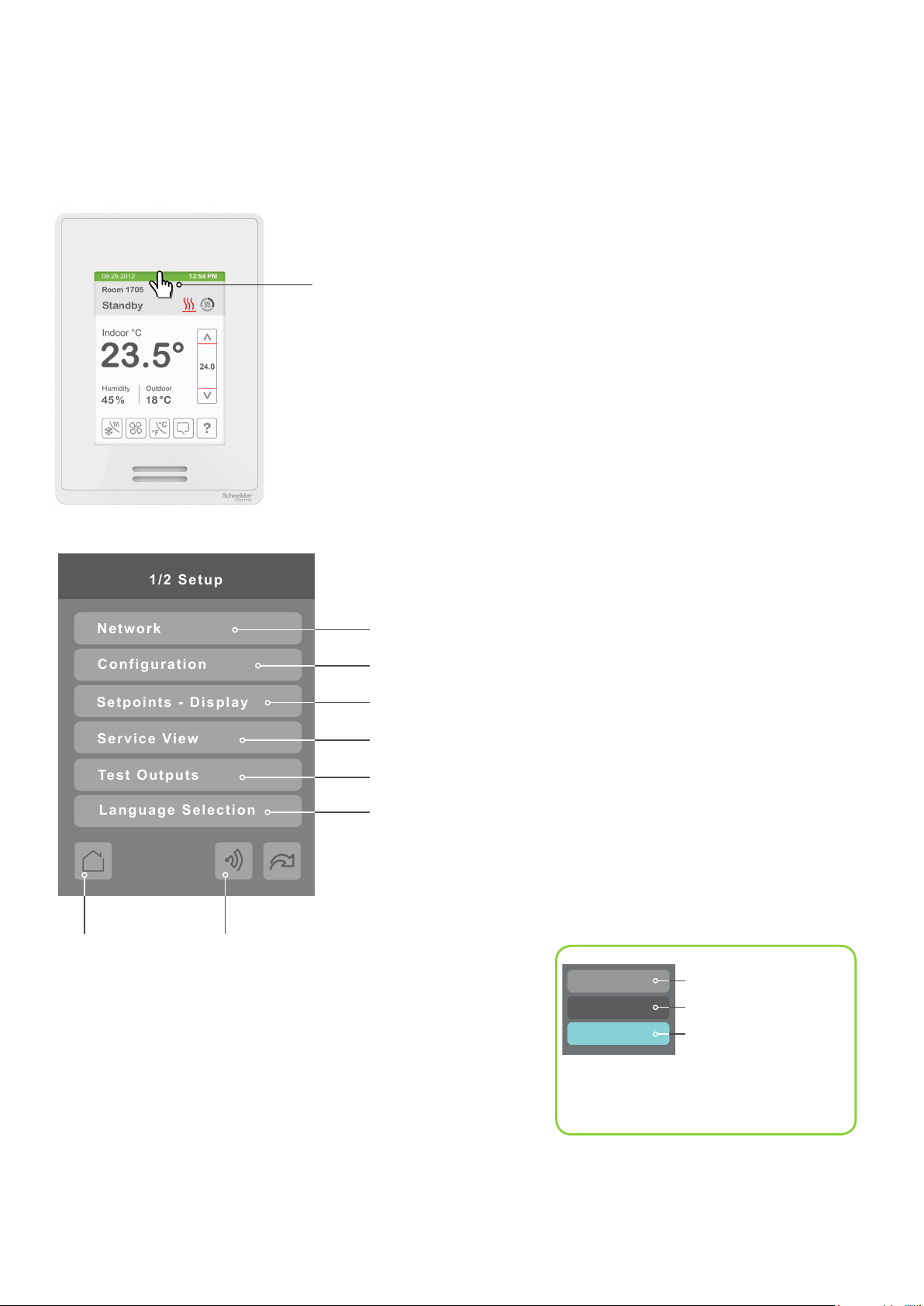
Enter Set-up Screen
1/2 Setup
Network
Configuration
Setpoints - Display
Service View
Test Outputs
Language Selection
Touch and hold this point
for 3 seconds to enter setup mode
Note: If a conguration/installer
password is activated to prevent
unauthorised access to the
conguration menu parameters, a
password entry prompt shows to
prevent access to device
conguration components.
3
SET-UP SCREEN DISPLAY
Enter BACnet® & ZigBee® network settings (only if ZigBee is detected)
Enter parameter conguration menu
Enter setpoint and display settings
Enter status and service view
Enter output testing mode
Enable selected language(s)*
Return to
home screen
Note: The following menus show according to context:
- ZigBee menu shows if ZigBee card detected.
- Network choice inside does not show if no network is available
Discover Mode The Controller
becomes discoverable on the wireless
ZigBee® network for 1 minute (this
button is hidden if ZigBee® settings are
not congured)
General Note:
Adjustable parameter
Nonadjustable parameter
Indicates invisible conditional
eld. Appears based only
on model, presence of a
ZigBee® wireless adapter
module or presence of a
Lua script, depending on the
eld.
*only available in recent versions of rmware
4
Schneider Electric | UI-SE8 300 -HMI- A4.EN.01.2017.v8 January 2017
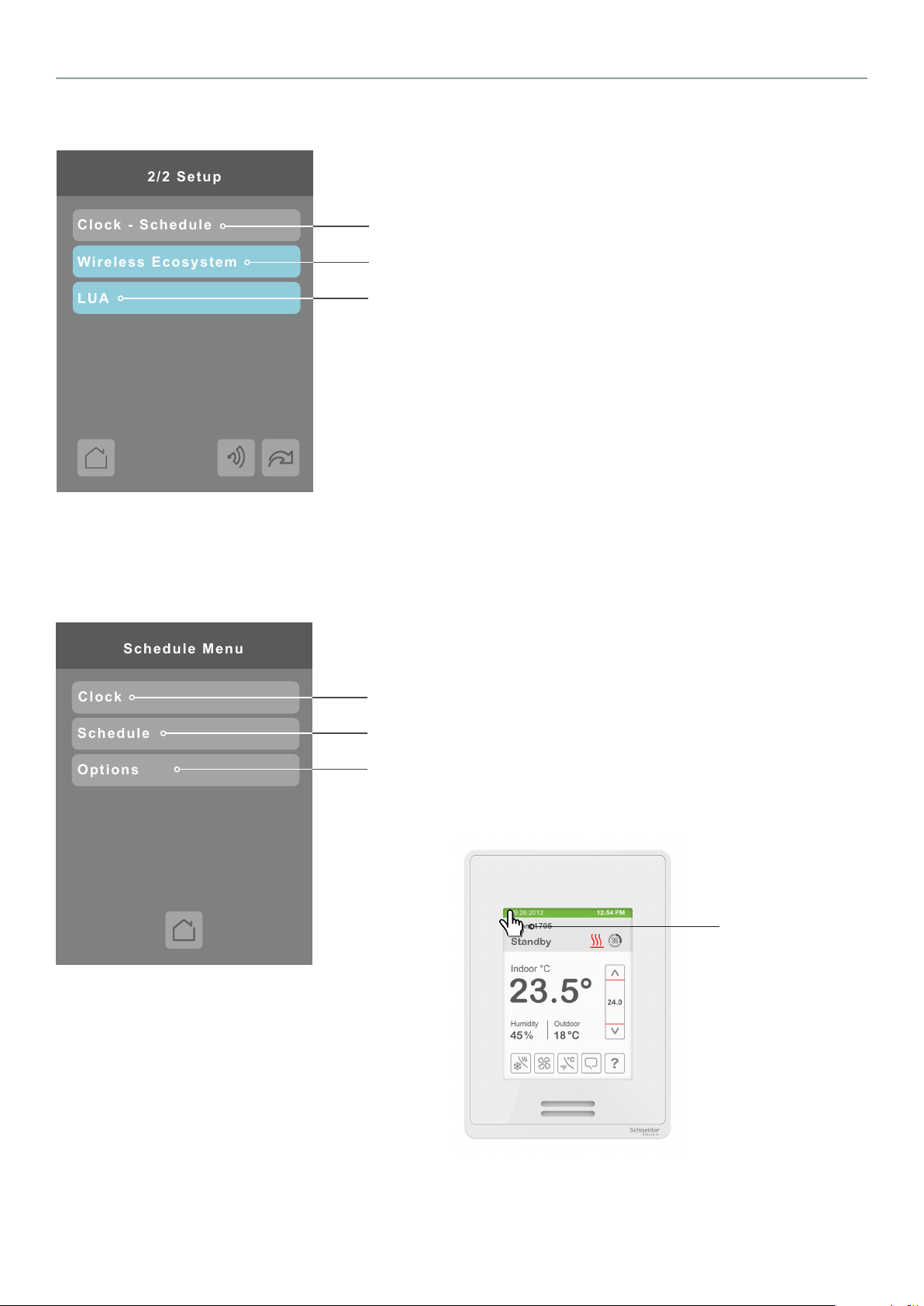
2/2 Setup
Clock - Schedule
LUA
Wireless Ecosystem
Options
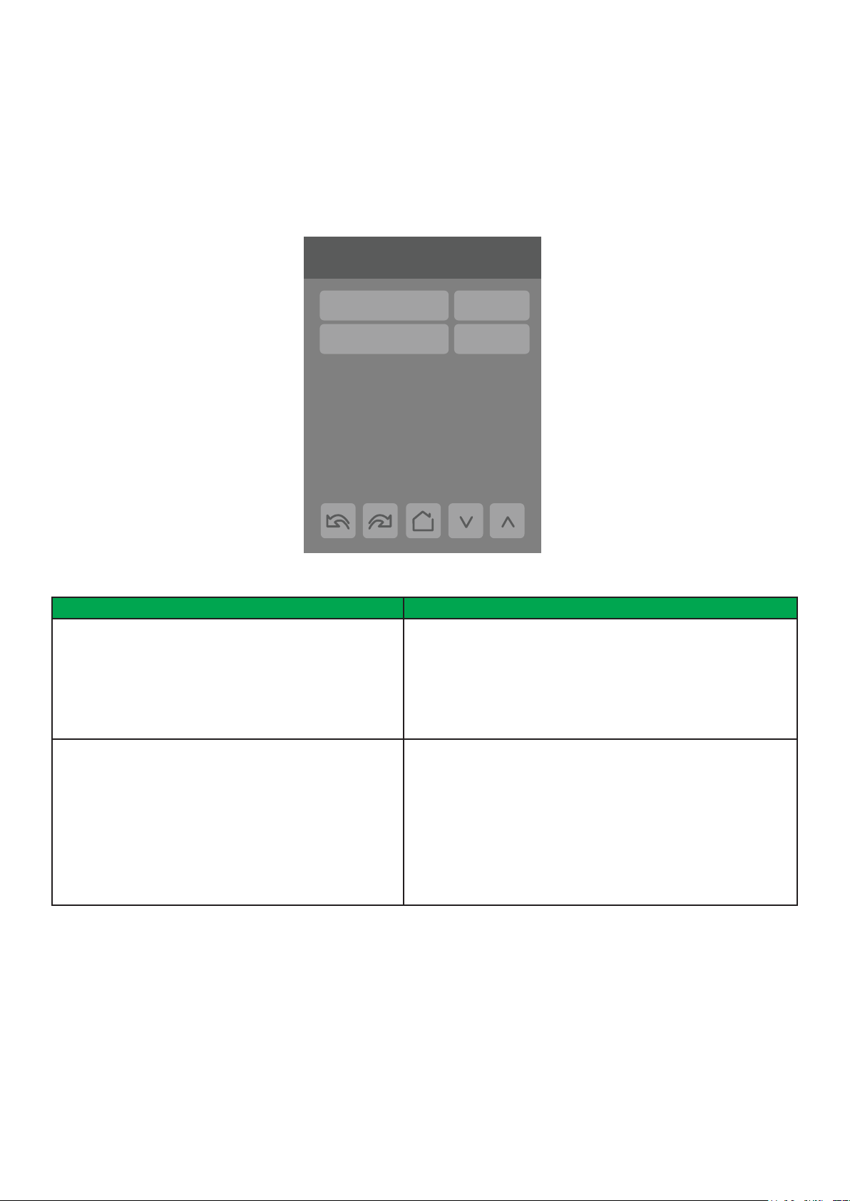
Schedule Menu
Clock
Schedule
SET-UP SCREEN DISPLAY 2/2
Enter Schedule menu screen
Enter Wireless Ecosystem settings (ZigBee wireless adapter module required)
Enter LUA script settings (Lua script required)
SCHEDULE MENU SCREEN
Enter Clock settings
Enter Schedule settings
Enter Option settings
Note: The Schedule menu screen is directly
accessible from the main display if the Schedule
Menu conguration parameter is enabled. See
Conguration Parameters Screen 6/7 on page 26 for
more information.
Touch and hold this
point for 3 seconds
to enter the Schedule
Menu screen.
Schneider Electric | UI-SE8 300 -HMI- A4.EN.01.2017.v8 January 2017
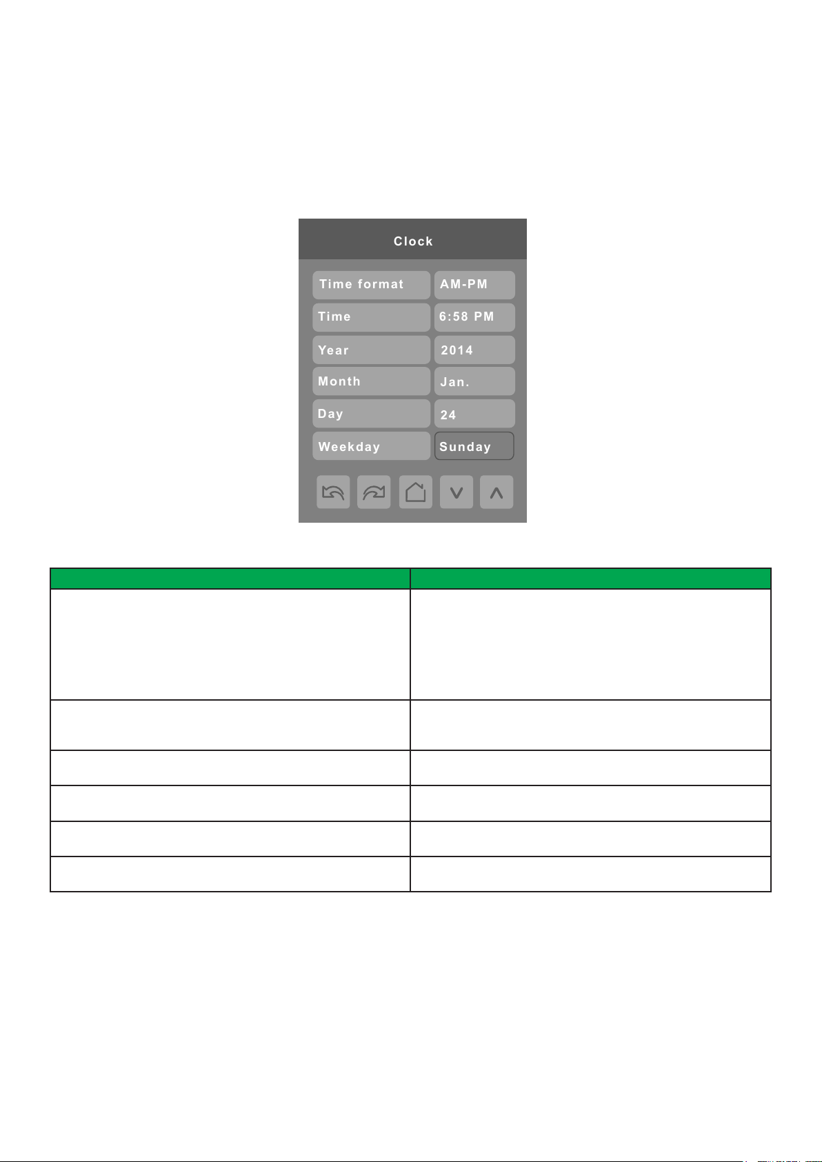
CLOCK SETTINGS
Clock
Time format
AM-PM
6:58 PM
Time
2014
Year
Month
Day
Weekday
24
Jan.
Sunday
The Clock settings screen allows the device’s internal time settings to be changed, including current time, standard day, month,
year and weekday options, as well as choice between a 12 hour AM / PM display or a 24 hour display.
5
PARAMETER DETAILS
Conguration parameters default value Signicance and adjustments
Time Format
Current time display format
Default value: AM-PM
Time
Current time display setting
Default value: Begins at 12:00 AM at initial power up.
Year
Default value: 2000
Month
Default value: Jan.
Day
Default value: 01
Weekday
Default value: Sunday
Choice between 12 hour AM - PM time format or 24 hour time
format.
AM-PM
24 Hours
Note: Changing the value of this parameter automatically
changes the format of the displayed value of the Time
parameter directly below.
Standard time display, 12 hour AM-PM or 24 hour; format is
determined by the Time Format parameter value.
Current year
Current month
Current day
Current day of the week
6
Schneider Electric | UI-SE8 300 -HMI- A4.EN.01.2017.v8 January 2017
--:--
--:--
**** Schedule
Occupied 1
Unoccupied 1
--:--
--:--
Occupied 2
Unoccupied 2
--:--
--:--
Occupied 3
Unoccupied 3
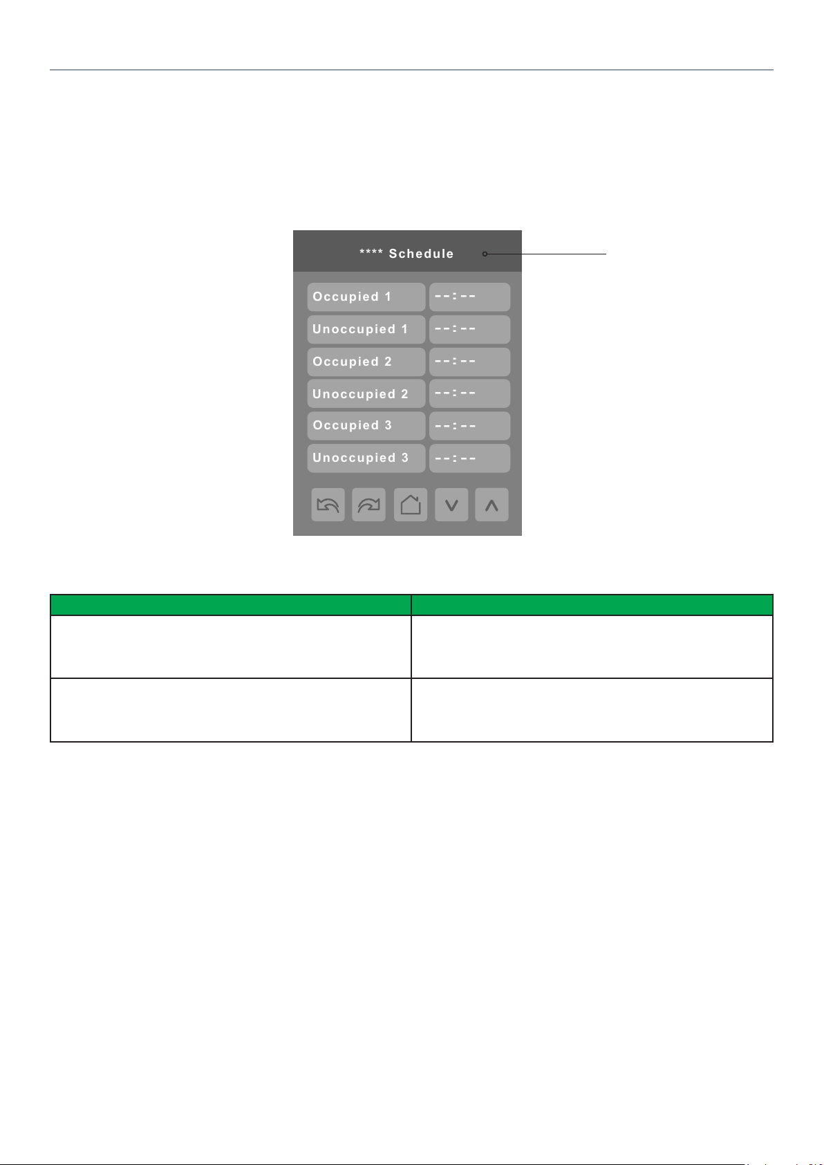
SCHEDULE SETTINGS
There are 7 different schedule setting screens, one for each day of the week, titled accordingly. Each day can have different
scheduled events where the room controller is set to Occupied status or back to Unoccupied status and use the appropriate
setpoints, back and forth up to 3 times per day.
Screen title is identied by
day of the week (Sunday
through Saturday)
PARAMETER DETAILS
Conguration parameters default value Signicance and adjustments
Occupied
Default value: None
Unoccupied
Default value: None
Denes a time when the room controller is automatically set to
use the Occupied setpoint.
Note: There are 3 separate Occupied parameter entries.
Denes a time when the room controller is automatically set to
use the Unoccupied setpoint.
Note: There are 3 separate Unoccupied parameter entries.
Schneider Electric | UI-SE8 300 -HMI- A4.EN.01.2017.v8 January 2017
OPTIONS SETTINGS
The options settings screen allows you to determine how the Room Controller will determine whether it is functioning in Occupied
or Unoccupied mode and scheduling.
6/7 Configuration
Options
Language English
Occupancy cmd Loc occ.
Schedule type 7 days
Units °C
Low backlight 60 %
Night backlight 5 %
RH display Disable
7
PARAMETER DETAILS
Conguration parameters default value Signicance and adjustments
Occupancy cmd
Default value: Local occ
Schedule type
Default value: 7 days
Occupancy Command
Loc occ: occupancy is determined by local sequences (either PIR
or schedule, as congured under Occ. source).
Occupied: force occupied mode.
Unoccup: force unoccupied mode.
Schedule type Command
7 days: Independent scheduling; title is identied by day of the
week (Sunday through Saturday).
5+1+1 days: Weekdays scheduling and Independent Weekend
scheduling; title is identied as Weekdays, Saturday and Sunday.
5+2 days: Weekdays scheduling and Weekend scheduling; title is
identied as Weekdays and Weekend.
8
Schneider Electric | UI-SE8 300 -HMI- A4.EN.01.2017.v8 January 2017
Set function to
Status
1/10 Zone
Battery
Not paired
Comm. status
0x0000
IEEE addr.
None
Closed
Normal
Permit join
On
Set function to
Status
10/10 Zone
Battery
No
Comm. status
0x0000
IEEE addr.
None
Closed
Normal
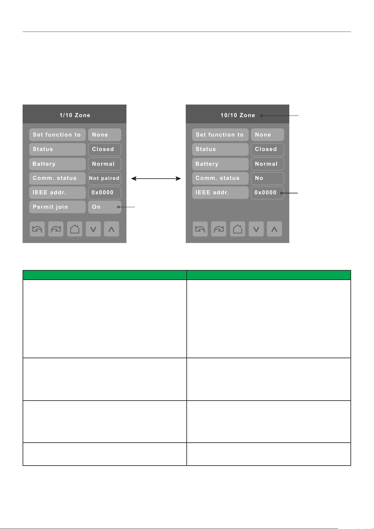
WIRELESS ECOSYSTEM
When ZigBee wireless sensors are set up to communicate with a Room Controller, the functioning of each such sensor is
described in a separate Zone screen, up to a maximum of 10 Zones. Select the appropriate type of sensor based on the required
functioning using the up and down arrow keys.
Up to 10 separate
wireless sensors
can be congured,
each with its own
Zone screen
Identical to ZigBee
settings display
parameter, see
page 11
PARAMETER DETAILS
Conguration parameters default value Signicance and adjustments
Set function to
Describe function of specied wireless sensor
Default value: None
Status
Current status of information received from the sensor
Read only
Battery
Current status of sensor battery, if any.
Read only
Comm. Status
Sensor pairing state
Read only
Only last 4 digits
in HEX shown
None: No sensor function congured for this zone
Door: Sensor is a door contact switch
Window: Sensor is a window contact switch
Motion: Sensor is a motion sensor
Status: Updates the BACnet status of the sensor, but no
action is taken by the internal logic of the controller.
Remove: Selecting this function clears the zone of the settings
for the attached sensor. However, the sensor will automatically
try to reconnect with the room controller unless it is manually
reset as well.
Close: Sensor in closed state (door/window only)
Open: Sensor in opened state (door/window only)
No motion: Sensor detects no motion (motion sensor only)
Motion: Sensor detects motion (motion sensor only)
None: No status information received from sensor.
Low: Battery power level is low, replacement or recharge will
be needed soon
Normal: Battery power level is in the normal range,
replacement or recharge is not currently needed.
None: Sensor does not use a battery
Default: Not paired
Choices: Not paired, Online, Invalid, Ofine
Schneider Electric | UI-SE8 300 -HMI- A4.EN.01.2017.v8 January 2017
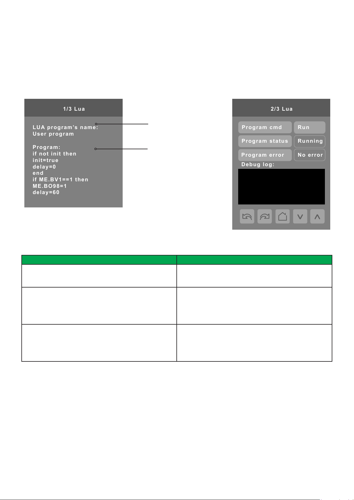
LUA SETTINGS
1/3 Lua
LUA program’s name:
User program
Program:
if not init then
init=true
delay=0
end
if ME.BV1==1 then
ME.BO98=1
delay=60
2/3 Lua
Debug log:
Program cmd
Program status
Program error
Run
Running
No error
The LUA settings screens show information about any custom LUA script uploaded to the controller. LUA scripts are not
programmable on the controllers, and so must be uploaded to the controllers.
The title of the LUA script
is shown here
The body of the LUA
script is shown here
9
PARAMETER DETAILS
Conguration parameters default value Signicance and adjustments
Program cmd
Default value: Run
Program status
Read only
Program error
Read only
Run: The LUA script is activated and will run continuously until
deactivated.
Stop: The LUA script is deactivated
Running: The LUA script is current active
Halted: The LUA script has been stopped and is not active.
Idle: The LUA script is running but is not currently taking any
actions
Waiting: The LUA script is running and waiting for a response.
No error: No errors in the LUA script are detected.
Syntax: A syntax error in the LUA script is detected
Runtime: A runtime error has occurred while running the LUA
script.
Memory: The device has run out of memory for the script
10
Schneider Electric | UI-SE8 300 -HMI- A4.EN.01.2017.v8 January 2017
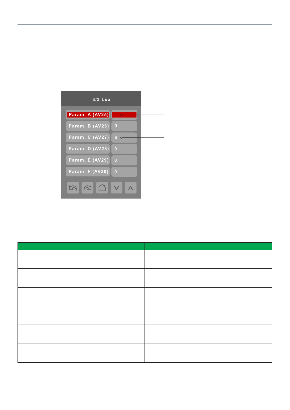
3/3 Lua
0
8
Param. B (AV26)
Param. C (AV27)
Param. D (AV28)
Param. E (AV29)
Param. F (AV30)
0
0
0
Param. A (AV25)
LUA GENERIC PARAMETERS
The LUA settings include six generic parameters that do not have predened values. These can be used to represent LUA script
variables. They are user congurable in their default state, but when they are assigned a value by a LUA script they become read
only, and the display colour of the parameter changes to red. These parameters are also modiable through BACnet as Analog
Values (AVs). These parameters can be congured to receive information from ZigBee sensors.
PARAMETER DETAILS
Conguration parameters default value Signicance and adjustments
Parameter A
Default value: 0
Default value can be changed by user
Parameter B
Default value: 0
Default value can be changed by user
Parameter C
Default value: 0
Default value can be changed by user
Parameter D
Default value: 0
Default value can be changed by user
Parameter E
Default value: 0
Default value can be changed by user
Parameter F
Default value: 0
Default value can be changed by user
5
A parameter dened by a LUA
script displays in red text.
The default value is normally 0,
but it can be user-congured to
use a different default value.
AV25
The value(s) of this parameter depends on what is assigned to
it using the LUA script function
AV26
The value(s) of this parameter depends on what is assigned to
it using the LUA script function
AV27
The value(s) of this parameter depends on what is assigned to
it using the LUA script function
AV28
The value(s) of this parameter depends on what is assigned to
it using the LUA script function
AV29
The value(s) of this parameter depends on what is assigned to
it using the LUA script function
AV30
The value(s) of this parameter depends on what is assigned to
it using the LUA script function
Schneider Electric | UI-SE8 300 -HMI- A4.EN.01.2017.v8 January 2017
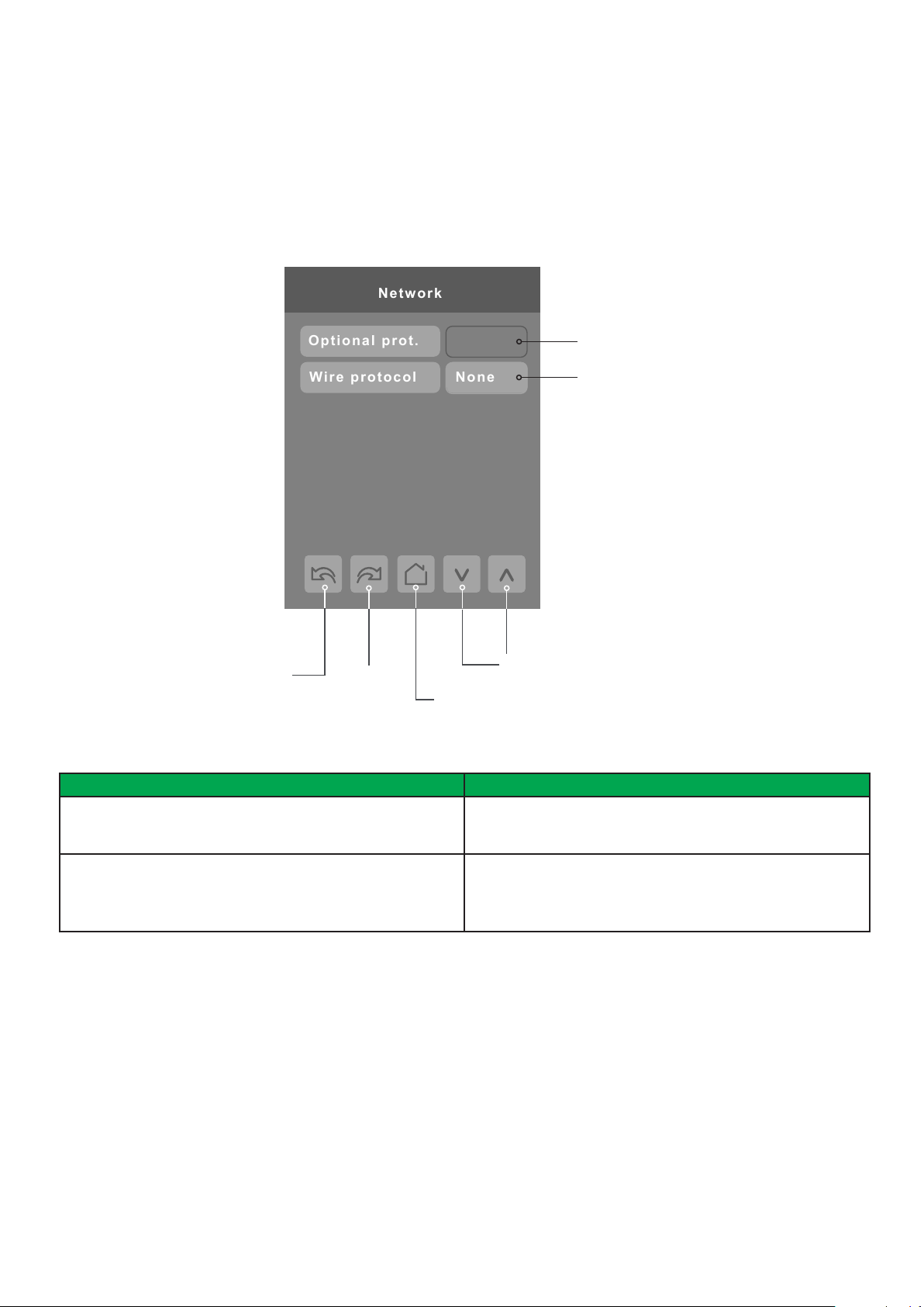
NETWORK SETTINGS
Network
None
Wire protocol
Optional prot.
Network screen shows if a ZigBee card is detected and selection between BACnet or Modbus network protocols.
11
Previous
Page
PARAMETER DETAILS
Conguration Parameters Default Value Signicance and Adjustments
Optional prot.
Default value: None
Default value can be changed by user
Wire protocol
Default value: None
Next
Page
None
ZigBee card detection
Wired network protocol selection
Change Value
( see note )
Back to
Setup Page
None: No ZigBee card detected
ZigBee: ZigBee card detected
None: No wired protocol congured
BACnet: Enable BACnet network protocol
Modbus: Enable Modbus network protocol
12
Schneider Electric | UI-SE8 300 -HMI- A4.EN.01.2017.v8 January 2017
ZIGBEE PRO NETWORK SETTINGS
ZigBee Pro set-up screen shows when ZigBee card is detected in model. Select desired parameter and use up or down arrow to
set parameter to desired value.
1/3 Zigbee network
COM address 254
Node type Router
ZigBee PAN ID 25
ZigBee channel 15
ZigBee short 0x0000
ZigBee® Pro short
address. The address is
generated once device
joins a ZigBee® network
PARAMETER DETAILS
Conguration parameters default value Signicance and adjustments
Com address
Terminal Equipment
Controller networking address
Default value: 254
Range value: 0 - 254
Previous
Page
ZigBee status No NWK
Next
Page
Back to
Setup Page
Communication Address
For wireless models, the use of the COM address is not
mandatory.
The COM address is an optional way to identify a device on
the network.
Status of controller
detecting a ZigBee®
network. Shows Online
when connected
successfully to network
Change Value
( see note )

Schneider Electric | UI-SE8 300 -HMI- A4.EN.01.2017.v8 January 2017
PARAMETER DETAILS
Conguration parameters default value Signicance and adjustments
ZigBee Pan ID
Personal Area Network
Identication
Default value: 0
Range value: 1 - 1000
ZigBee channel
Channel selection
Default value: 10
Range value: 10 - 25
13
ZigBee Pro PAN ID
Links specic Terminal Equipment Controllers to
specic ZigBee® Pro coordinators. For every Terminal
Equipment Controller reporting to a coordinator. Ensure set
the SAME channel value both on the coordinator and the
Terminal Equipment Controller(s).
Default value of 0 is NOT a valid PAN ID. The valid range of
available PAN IDs is from 1 to 1000.
Range 1 to 500 for centralized networked applications using
a ZigBee® Pro Coordinator.
Range 501 to 1000 is for stand-alone applications where
each controller is its own coordinator for stand alone
installation of wireless door and window switches.
ZigBee channel
This parameter links specic Terminal Equipment Controllers
to specic ZigBee® Pro coordinators. For every Terminal
Equipment Controller reporting to a coordinator, ensure you
set the SAME channel value both on the coordinator and the
Terminal Equipment Controller(s).
ZigBee status
Read only
Using channels 15 and 25 is recommended.
The default value of 10 is NOT a valid channel. The valid
range of available channels is from 11 to 25.
ZigBee status
The following read only messages show in this eld:
Not Det: ZigBee® Pro module not detected
Pwr On: ZigBee® Pro module detected but not congured
No NWK: ZigBee® Pro congured but no network joined
Joined: ZigBee® Pro network joined
Online: Communicating
14
Schneider Electric | UI-SE8 300 -HMI- A4.EN.01.2017.v8 January 2017
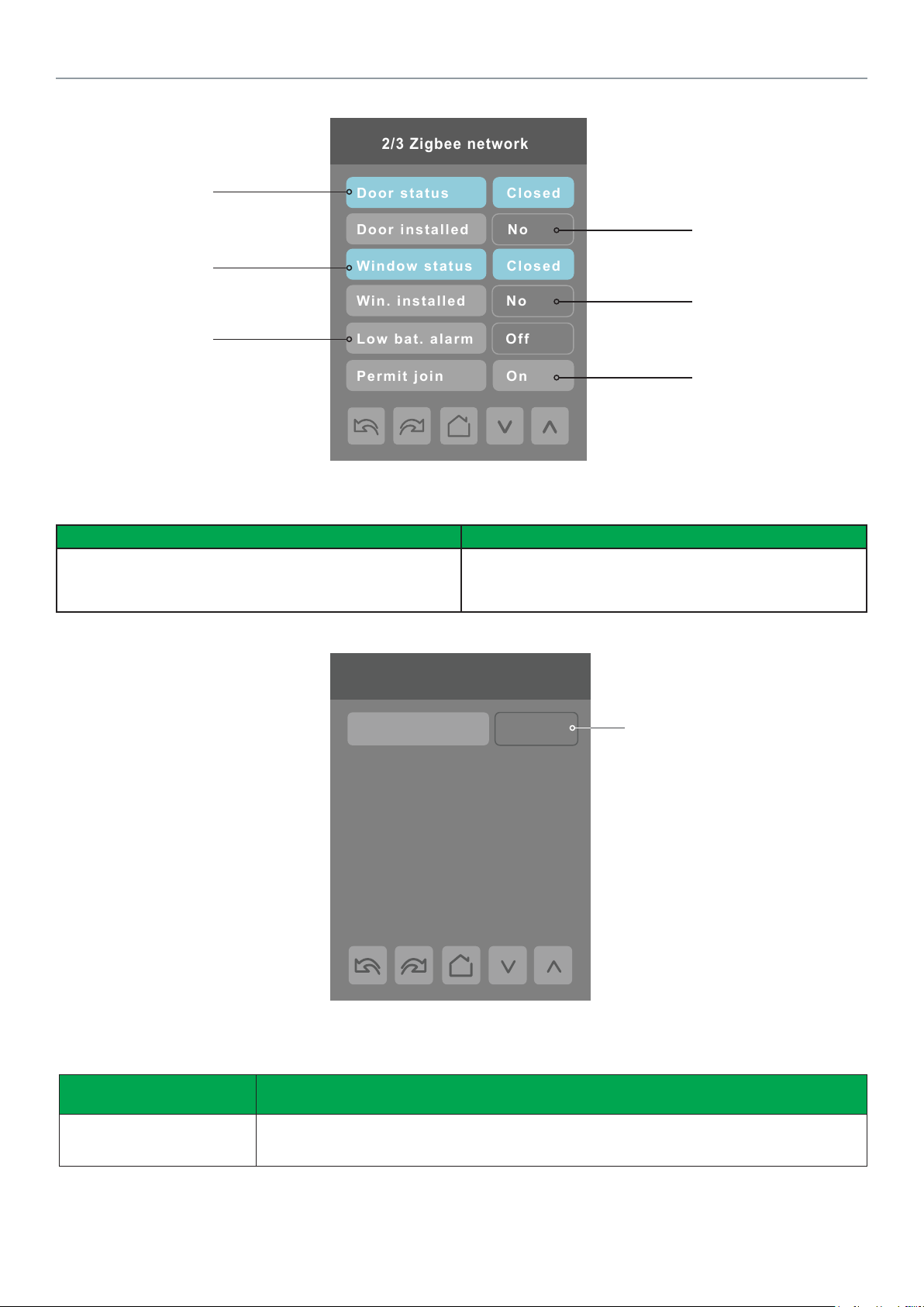
2/3 Zigbee network
Door status
Closed
Door installed
No
Window status
Closed
Win. installed
No
Permit join
On
Low bat. alarm
Off
Door contact
status if installed
Window contact
status if installed
Battery status
of wireless switch
Note: Display returns to home screen
when no activity is detected for 1
minute.
PARAMETER DETAILS
Indicates if door contact is
installed
Indicates if window contact
is installed
Automatically allows
ZigBee® Pro devices to
join the network through
this controller.
Conguration parameters default value Signicance and adjustments
Permit join
Default value: On
Permit Join
Changing this value to Off prevents any new ZigBee® Pro
devices from joining network through this controller.
3/3 Zigbee network
IEEE address 0x0000
Only last 4 digits in HEX
show
Note: The display will return to the home screen when no activity is detected for 1 minute.
PARAMETER DETAILS
Conguration parameters
default value
IEEE address
Default value = 0x0000
Signicance and adjustments
The extended IEEE ZigBee® node address is used to identify the device on the network.
Schneider Electric | UI-SE8 300 -HMI- A4.EN.01.2017.v8 January 2017
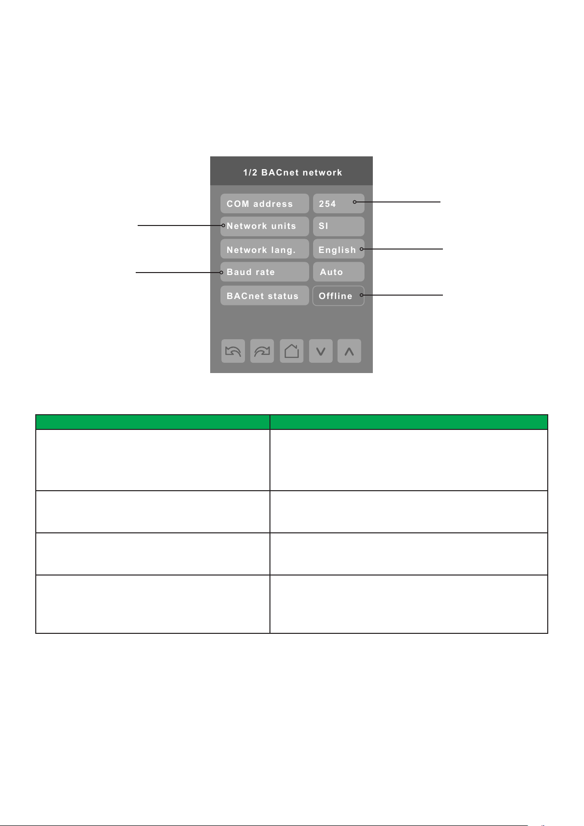
BACNET NETWORK SETTINGS
1/2 BACnet network
Baud rate
Auto
Network units
SI
Network lang.
English
BACnet status
Offline
COM address
254
BACnet network set-up screen shows when BACnet is detected in model. Select desired parameter and use up or down arrow to
set parameter to desired value.
15
Imperial or
Metric units
Baud rate
settings
PARAMETER DETAILS
Conguration parameters default value Signicance and adjustments
Comm address
Terminal Equipment Controller
networking address
Default value: 254
Range: 0 to 254
Network units
Default value: Imperial
Network lang
Default value: English
Baud rate
Default value: Auto
254 value sets BACnet
network Ofine. Choose
different value to activate
Online
Language setting
Displays BACnet status,
Ofine or Online
Communication Address
For BACnet® MS-TP models, the valid range is from 1 to 127.
Default value of 254 disables BACnet® communication for the Terminal Equipment Controller.
Measurement Units
Imperial: network units shown as Imperial units.
SI: network units shown as International Metric units.
Language Settings
Choice of network language/object names transmitted over network.
All available choices: (English, French, and Spanish).
Baud Rate
Auto: automatically detects BACnet® MS/TP baud rate.
Other choices: (115200, 76800, 57600, 38400, 19200, and 9600).
Leave the value at auto unless instructed otherwise.
®
16
Schneider Electric | UI-SE8 300 -HMI- A4.EN.01.2017.v8 January 2017
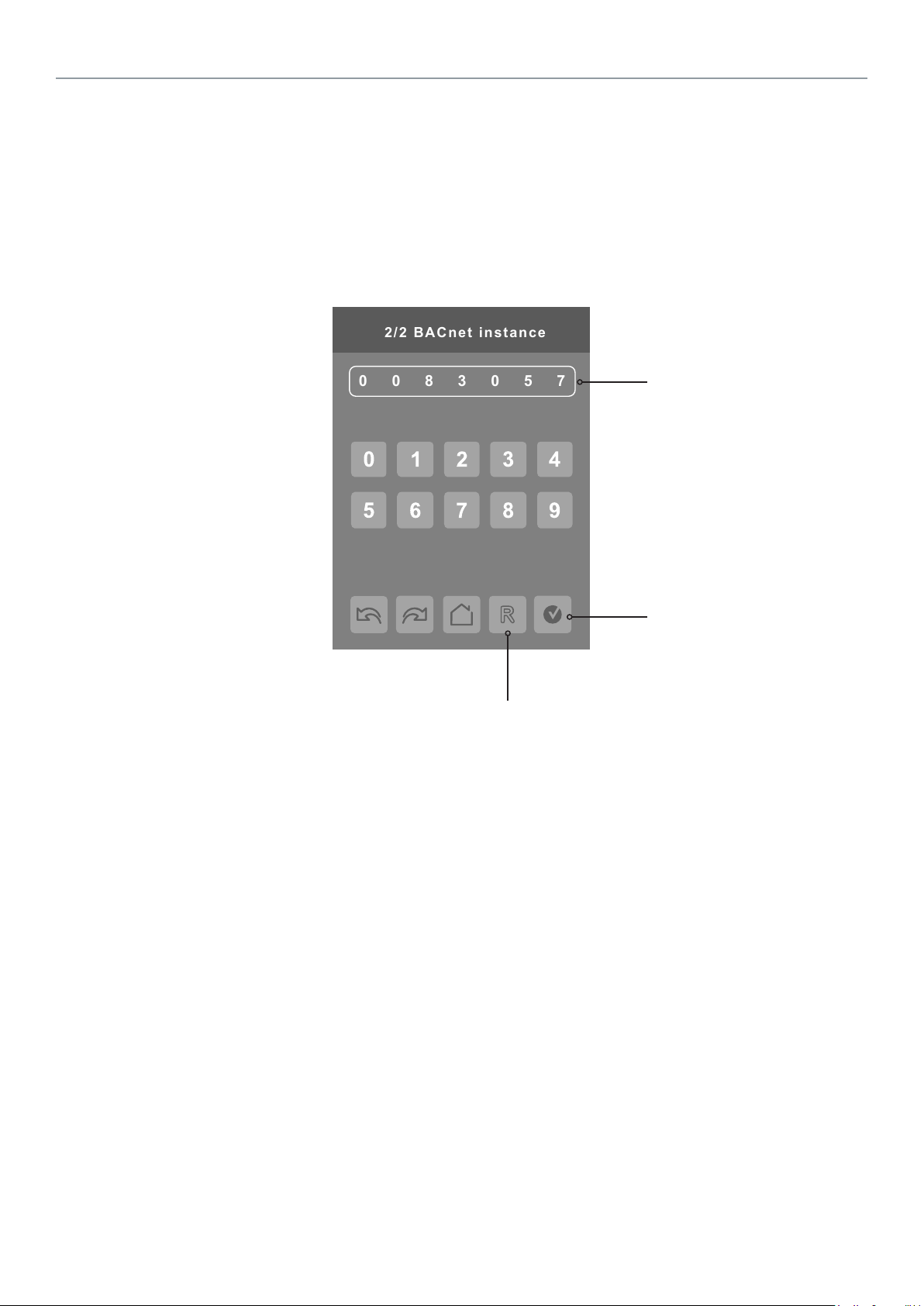
0830057
2/2 BACnet instance
BACNET INSTANCE NUMBER
The default BACnet® instance number is generated by the model number and COM address of the controller. For example, the
instance number of a SE8300U5B00 with a COM address of 57 is generated as “83057”.
The default instance number appears rst. To change the instance number, use number pad and press Accept and save.
Press Reset to automatic instance addressing to reset to automatic instance addressing.
Instance number of controller
Reset to automatic
instance addressing
Accept and save

Schneider Electric | UI-SE8 300 -HMI- A4.EN.01.2017.v8 January 2017
MODBUS NETWORK SETTINGS
1/1 Modbus network
Parity
None
Network units
SI
Baud rate
19200
COM address
254
Modbus network set-up screen shows when Modbus is detected in model. Select desired parameter and use up or down arrow to
set parameter to desired value.
254 value sets Modbus
network Ofine. Choose
Imperial or
Metric units
Baud rate
settings
different value to activate
Online
Parity checking
17
PARAMETER DETAILS
Conguration Parameters Default Value Signicance and Adjustments
Comm address
Terminal Equipment Controller
networking address
Default value: 254
Range: 0 to 254
Network units
Default value: Imperial
Baud rate
Default value: 19200 + Even Parity
Parity
Default value: None
Communication Address
Default value of 254 disables Modbus communication for the
Terminal Equipment Controller.
Measurement Units
Imperial: network units shown as Imperial units.
SI: network units shown as International Metric units.
Baud Rate
Auto: automatically detects baud rate.
Other choices: (115200, 76800, 57600, 38400, 19200, and
9600).
Leave the value at auto unless instructed otherwise.
Parity
Parity checking of the data character frame (Even, Odd, or no
parity (None)).

18
Schneider Electric | UI-SE8 300 -HMI- A4.EN.01.2017.v8 January 2017
CONFIGURATION PARAMETERS SCREEN 1/8
1/8 Configuration
UI16 config None
UI17 config None
UI19 config None
Occupancy src Motion
Smart recovery Off
Setpoint func. Attach SP
PARAMETER DETAILS
Conguration parameters default value Signicance and adjustments
UI 16
Universal input no.1 conguration
Dry contact to 24 Vac Com.
Default value: None
(MV46 = 1)
None: No function will be associated with the input. Input can be
used for remote network monitoring.
Rem NSB: Occupancy input via a dry contact to 24 Vac Com.
• Open contact = Occupied
• Closed contact = Unoccupied
Window: Disables instantly Heating and Cooling outputs if a
window and/or patio door is opened. The Fan output(s) remain
operational.
• Open contact = Window opened, disables Heat and Cool and
display “Window” alarm
• Closed contact = Normal operation
Motion NO: Remote Occupancy sensor with a Normally Opened
contact, contact closure = Motion.
Motion NC: Remote Occupancy sensor with a Normally Opened
contact, contact closure = Motion.
Fan lock: When (G) Fan output is activated, if this input is not
activated after 10 seconds, the thermostat will disable Heat and
Cool outputs and display “Fan Lock” alarm.
• Open contact = No airow alarm
• Closed contact = Airow present, normal operation

Schneider Electric | UI-SE8 300 -HMI- A4.EN.01.2017.v8 January 2017
PARAMETER DETAILS
Conguration parameters default value Signicance and adjustments
UI 17
Universal input no.2 conguration
Default value: None
UI 19
Universal input no.3 conguration
Default value: None
Occupancy src
Default value: Motion
Smart recovery
Smart recovery enabled
Default value: Off
Smart recovery is automatically disabled if UI 16 and / or
UI 17 are congured remote NSB
Setpoint func.
Local setpoint settings
Default value: Dual SP
19
Universal Input No. 2
None: no function associated with input.
Door Dry: door contact and motion detector.
Override: temporary occupancy remote override contact.
Filter: backlit ashing lter alarm shows on the Terminal
Equipment Controller LCD screen when the input is energized.
Service: backlit ashing Service alarm shows on Terminal
Equipment Controller LCD screen when input is energized.
Universal Input No. 3
None: no function associated with input though input can be used
for remote network monitoring.
COC/NH: change over dry contact; normally heat. Used for hot/
cold water or air change over switching in 2 pipe systems.
COC/NC: change over dry contact; normally cool. Used for hot/
cold water or air change over switching in 2 pipe systems.
COS: change over sensor. Used for hot/cold water or air
changeover switching in 2 pipe systems.
Occupancy Source
Local Motion: the local occupancy status is received from a
motion sensor.
Local Schedule: the local occupancy status is determined by the
schedule.
Note: Occ command in the schedule menu can be set to Local
Occ in which case Local occ points to Occ source.
Off = no smart recovery
The occupied schedule time is the time at which the system will
restart.
On = smart recovery active.
The occupied schedule time is the time at which the desired
occupied temperature will be attained. The controller will
automatically optimise the equipment start time.
In any case, the latest a system will restart is 10 minutes prior to
the occupied period time.
Setpoint function
Set the local setpoint interface for the user
Dual SP (Dual Occupied Setpoints Adjustment)
Attach SP (Two Occupied Setpoint Adjustment)

20
Schneider Electric | UI-SE8 300 -HMI- A4.EN.01.2017.v8 January 2017
CONFIGURATION PARAMETERS SCREEN 2/8
2/8 Configuration
Mode button Normal
Auto mode Enabled
Fan menu On-Auto
Auto fan func. AS
Standby mode Absolute
Standby diff. 2.0 °C
PARAMETER DETAILS
Conguration parameters default value Signicance and adjustments
Mode button
Default value: Normal
Auto mode
Default value: On
Fan menu
Default value: On-Auto
Mode button
Normal: Displays temperature Setpoints on main screen
Off-auto: Hides or simplies temperature Setpoints on main screen
Auto Mode
Enables auto function for the mode button
For sequences 2, 4, and 5 only
On: auto active (Off-Cool-Heat-Auto)
Off: auto not active (Off-Cool-Heat)
Fan Speeds
User fan menu presented is dependent on selected fan sequence of
operation for the fan coil.
L-M-H: 3 Speed conguration using 3 fan relays.
L-H: 2 Speed conguration using 2 fan relays.
L-M-H-A: 3 Speed conguration with Auto fan speed mode using
3 fan relays. Auto Mode operation is dependent on Auto Fan
parameter.
L-H-A: 2 Speed conguration with Auto fan speed mode using 2 fan
relays. Auto Mode operation is dependent on Auto Fan parameter.
On-Auto: single Speed conguration. Auto is for Fan on demand/
On is On all the time.

Schneider Electric | UI-SE8 300 -HMI- A4.EN.01.2017.v8 January 2017
PARAMETER DETAILS
Conguration parameters default value Signicance and adjustments
Auto fan func.
Auto Fan Function
Default value: AS
Standby mode
Default value: Abs
Standby diff.
Default value: 2 °C ( 3 °F )
21
Automatic Fan Function
Auto Speed Fan Mode operation for Fan Menu (L-M-H-A) or
(L-H-A).
AS: In Occupied, Standby and Override modes, the Fan stays ON
at Low speed even if there is no demand for Heating or Cooling.
In Unoccupied mode the Fan turns Off all speeds when there is no
demand for Heating or Cooling.
AS/AD: In any Occupancy mode, the Fan turns Off all speeds when
there is no demand for Heating or Cooling.
Standby Mode
Choose which standby setpoints are used for control.
Abs: absolute; Standby entered values are used for standby mode.
Offset: offset; Occupied setpoints +/- Standby diff. used for standby
mode.
Standby Difference
When Standby mode is Relative, standby setpoints are calculated
as:
Standby cool: Cool setpoint + Standby diff.
Standby heat: Heat setpoint - Standby diff.
Adjustable from 0.5 a 2.5 °C ( 1 - 5 °F )

22
Schneider Electric | UI-SE8 300 -HMI- A4.EN.01.2017.v8 January 2017
3/8 Configuration
Temp. occ. time
Unocc. time
Standby time
2.0 hrs
0.0 hrs
0.5 hrs
Deh. hysteresis
5.0% RH
Deh. max. cool
100%
Deh. lockout
Enabled
CONFIGURATION PARAMETERS SCREEN 3/8
These parameters are only displayed
on models with built in humidity sensor
PARAMETER DETAILS
Conguration parameters default value Signicance and adjustments
Standby time
Default value: 0.5 hours
Unocc. time
Default value: 0.0 hours
Standby Time
Time delay between the moment where the PIR cover detects last
movement in the area, and the time which the Terminal Equipment
Controller stand-by setpoints become active.
Range: 0.5 to 24.0 hours in 0.5 hours increments.
Unoccupied Time
Time delay between the moment where the Terminal Equipment
Controller toggles to stand-by mode, and the time which the Terminal
Equipment Controller unoccupied mode and setpoints become
active.
Factory value 0.0 hours: Setting this parameter to its default value of
0.0 hours disables the unoccupied timer. This prevents the Terminal
Equipment Controller to drift from stand-by mode to unoccupied
mode when PIR functions are used.
Range: 0.0 to 24.0 hours in 0.5 hours increments.

Schneider Electric | UI-SE8 300 -HMI- A4.EN.01.2017.v8 January 2017
PARAMETER DETAILS
Conguration parameters default value Signicance and adjustments
Temp. occ. time
Default value: 2 hours
Deh. hysteresis
Default value: 5% RH
Deh. max. cool
Default value: 100%
Deh. lockout
Default value: Enabled
Temporary Occupancy Time
Temporary occupancy time with occupied mode setpoints when
override function is enabled.
When Terminal Equipment Controller is in unoccupied mode, function
is enabled with either the menu or UI2 congured as remote override
input.
Range: 0 - 24 hours.
Humidity Control Hysteresis
Used only if dehumidication sequence is enabled:
Range: 2 to 20% RH
Models with humidity sensor only.
Maximum Dehumidication Cooling
Maximum cooling valve position when dehumidication is enabled. This
can be used to balance smaller reheat loads installed in regards to the
capacity of the cooling coil.
Range: 20 to 100 %
Models with humidity sensor only.
Dehumidication Lockout
Typically toggled through the network. This variable enables or
disables dehumidication based on central network requirements from
the BAS front end.
Enabled: Dehumidication Authorized
Disabled: Dehumidication Not Authorized
Models with humidity sensor only.
23

24
Schneider Electric | UI-SE8 300 -HMI- A4.EN.01.2017.v8 January 2017
CONFIGURATION PARAMETERS SCREEN 4/8
4/8 Configuration
CPH 4
Control type Floating
BO8 out time 15 min.
BO8 aux. config Reheat
Floating time 1.5 min
Action DA
PARAMETER DETAILS
Conguration parameters default value Signicance and adjustments
CPH
Default value: 4 CPH
Control Type
Control type for Triac models
Default: Floating
Cooling Output Cycles/Hr
Sets maximum number cycles per hour under normal control operation.
It represents the maximum number of cycles equipment turns ON and
OFF in one hour.
A higher CPH represents a higher accuracy of control at the expense
of wearing mechanical components faster.
Range: 3, 4, 5, 6,7 and 8 CPH.
Control Output for FCU Valves
Denes type of control output for type of valves installed for the FCU
application
On/Off: normally opened or normally closed 24 VAC 2 position valves
Floating: modulating 3 wires control of 24 VAC oating valves
Analog: analog modulating control of 2-10 Vdc valves
Refer to proper control diagram according to selected control type
outputs.

Schneider Electric | UI-SE8 300 -HMI- A4.EN.01.2017.v8 January 2017
PARAMETER DETAILS
Conguration parameters default value Signicance and adjustments
BO8 out time
Default value: 0 = 15 minutes (4 CPH)
BO8 aux. cong
Aux contact function used for reheat if sequence is set
to use BO8 for reheat through network or local. Ignore
this parameter.
Default value: Reheat
Floating Time
Floating actuator stroke timing value
Default value: 1.5 minutes oating actuator timing
Reheat Output Time
Sets reheat output time base.
Valid only if reheat sequences are enabled.
0: 15 minutes
1: 10 seconds for solid state relays
Binary Output Terminal
Output directly follows occupancy of the Terminal Equipment
Controller.
1) Auxiliary NO: Occ or St-By = Contact Closed / Unoccupied =
Contact Opened
2) Auxiliary NC: Occ or St-By = Contact Opened / Unoccupied =
Contact Closed. Output to follow directly main occupancy and Fan on
command. Typically used for 2 position fresh air damper applications.
3) Auxiliary NO: Occ or St-By & Fan On = Contact Closed/
Unoccupied and Fan On or Off = Contact Opened
4) Auxiliary NC: Occ or St-By & Fan On = Contact Opened/
Unoccupied and Fan On or Off = Contact Closed
Floating Time
Maximum stroke time of oating valve actuator.
Range: 0.5 to 9.0 minutes in 0.5 minute increments
25
Action
For Analog Heating signals
Default value: DA signal
Direct Acting/Reverse Acting
Reverse Acting or Direct Acting signal for Analog Output signals
DA = 0 to 100 % = 0 to 10VDC
RA = 0 to 100 % = 10 to 0VDC

26
Schneider Electric | UI-SE8 300 -HMI- A4.EN.01.2017.v8 January 2017
5/8 Configuration
Operation seq.
No. of pipes
Prop. band
Heat only
2
3.0
Purge sample
0.0 hrs
Purge open
1 min
Temp. sensor
Remote
CONFIGURATION PARAMETERS SCREEN 5/8
PARAMETER DETAILS
Conguration parameters default value Signicance and adjustments
Prop. band
Default value: 3
Proportional Band Setting
Adjusts proportional band used by the Terminal Equipment Controller
PI control loop.
Note: default value of 3.0 gives satisfactory operation in most normal
installation cases. The use of a superior proportional band different
than the factory one is normally warranted in applications where
Terminal Equipment Controller location is problematic and leads to
unwanted cycling of the unit. A typical example is a wall mounted unit
where Terminal Equipment Controller is installed between return and
supply air feeds and is directly inuenced by the supply air stream of
unit.
Value Effective Proportional Band
Fahrenheit Celsius
3 3 1.2
4 4 1.7
5 5 2.2
6 6 2.8
7 7 3.3
8 8 3.9
9 9 5.0
10 10 5.6

Schneider Electric | UI-SE8 300 -HMI- A4.EN.01.2017.v8 January 2017
PARAMETER DETAILS
Conguration parameters default value Signicance and adjustments
No. of pipes
Default value: 4 pipes
Operation seq.
Default value: Sequence #1
Pipe Setting Type Installed
Denes type of system installed.
2 Pipes: limits number of sequences of operation available from
0 - 4. It also enables heat/cool operation from the same output.
4 Pipes: can access all sequences of operation from 0 - 2. Also
enables heat/cool operation from different output.
Sequence Operation
Selects initial sequence of operation required by installation type and
application.
System Modes System = 2 Pipes System = 4 Pipes
Off - Cool Cooling Only Cooling Only
Off - Heat Heating Only Heating Only
Off - Auto - Heat -
Cool
Cooling With Electric
Reheat
Off - Heat Heating With Electric
Reheat
Off - Auto - Heat -
Cool N/A
Off - Auto - Heat -
Cool N/A
For 2 Pipe output applications, the system
is limited if congured for local changeover
COS, COC/NC or COC/NC. The current
water temperature detected by the RU1 then
limits the system mode available for the local
conguration or network write.
27
Cooling With Electric
Reheat
Heating With Electric
Reheat
4 = Cooling and
Heating (2 modulat-
ing outputs)
5 = Cooling/Heating
(2 modulating out-
puts) with reheat
Purge sample
Default value: 2 hours
Purge open
Default value: 2 minutes
Temp. sensor
Default Value: Remote
Time interval between valve samples. Opens valve for a short period
adjusted by Purge open parameter to sample pipe temperature to
decide between heating or cooling mode.
Adjustable for 0 to 4 hours (0 = disable).
Time valve opens to sample pipe temperature to decide between heating or cooling mode.
Adjustable for 1 to 3 minutes.
Selection of room temperature sensor
• Remote: Room Controller uses internal temperature sensor only if
UI20 terminal is empty. If a valid temperature sensor is connected
on UI20 terminal, Room Controller will automatically disable its
internal sensor and use the remote sensor as control point. Disconnecting the sensor, or, if the sensor value is out-of-range, the
room controller will automatically re-enable its internal temperature sensor.
• Local: Room Controller uses internal temperature sensor even
if UI20 terminal is used. Typical use for return air temperature or
other temperature monitoring via BACnet point UI20. It can also
be used for average internal sensor with remote sensor using a
simple Lua4RC script.

28
Schneider Electric | UI-SE8 300 -HMI- A4.EN.01.2017.v8 January 2017
6/8 Configuration
User password
Main password
0
0
Schedule menu
Enabled
CONFIGURATION PARAMETERS SCREEN 6/8
PARAMETER DETAILS
Conguration parameters default value Signicance and adjustments
Main password
Default value: 0
User Password
Default value: 0
Schedule menu
Default value: Enabled
Toggles activation of schedule menu direct access
Main Password
Installer password. This parameter sets a protective access
password to prevent unauthorised access to conguration menu
parameters.
Default value of 0 does not prompt a password or lock access
conguration menu.
Range: 0 - 9999.
User Password
End user password. This parameter sets a protective access password
to prevent user unauthorised access to main screen adjustments.
Default value of 0 does not prompt a password.
Range: 0 - 9999.
Enabled: The Schedule Menu is directly accessible from the main
screen via a touch in the upper corner (see page 4).
Disabled: The Schedule Menu can only be accessed through the
Setup Menu screens.
Dis.no.clk: Clock function disabled.
En.no.clk: Clock function enabled.

Schneider Electric | UI-SE8 300 -HMI- A4.EN.01.2017.v8 January 2017
7/8 Configuration
Calib. temp.
0.0 °C
Calib. humid.
0.0 %RH
CO2 autocal.
Enabled
CONFIGURATION PARAMETERS SCREEN 7/7
Parameter only displayed on
models with built in humidity
sensor.
29
PARAMETER DETAILS
Conguration parameters default value Signicance and adjustments
Calib. temp.
Default value: 0.0 °C or °F
Calib. humid.
Default value: 0% RH
CO2 autocal.
Default value: Enabled
Calibration Temperature
Room temperature sensor calibration. Offset can be added or
subtracted to actual displayed room temperature.
Range: ± 2.5 °C, 0.5 °C increments ( ± 5.0 °F, 1.0 °F increments ).
Humidity Calibration
Humidity sensor calibration. Offset can be added or subtracted to
actual displayed humidity.
Range: ± 15.0 %RH (models with humidity sensor only).
Enable or Disable CO2 sensor auto calibration.

30
Schneider Electric | UI-SE8 300 -HMI- A4.EN.01.2017.v8 January 2017
8/8 Reinitialization
Push to accept:
Are you sure?
Erase all?
No
No
CONFIGURATION PARAMETERS SCREEN 8/8
PARAMETER DETAILS
Conguration parameters default value Signicance and adjustments
Erase all?
Default value: No
Are you sure?
Default value: No
Erase All
Answering Yes on both and pressing Accept button erases all values
and changes to factory default values except the following network
related values:
• COM address
• ZigBee® Pro Pan ID
• ZigBee® Pro channel
• Network units
• Network language
• Baud rate
• BACnet® instance
• Device name
• Screen Contrast

Schneider Electric | UI-SE8 300 -HMI- A4.EN.01.2017.v8 January 2017
PASSWORD SETTINGS
Installer Password
01234
56789
Enter the code
The following shows you how to enter the password for the Installer and User
Installer Password
31
1. Installer password prompt shows only if password value is greater than 0000. A password value of 0000 disables installer
password but does not restrict access to conguration options.
2. Installer password prompt automatically disappears after 10 seconds if no value is entered.
3. An error code is automatically generated if incorrect password is entered.
4. Installer is permitted access to all Installer functions and menus when correct password is entered.
NOTE: when the schedule menu is enabled OR when the 5th button is set to schedule or custom, the clock, occupancy
command, schedule or custom pages are NOT password-protected. Always use a system password when the Room Controller is
in regular use to avoid inadvertent changes of the Room Controller logic.

32
Schneider Electric | UI-SE8 300 -HMI- A4.EN.01.2017.v8 January 2017
User Password
01234
56789
Wrong code
User Password
1. User password prompt shows only if password value is greater than 0000. A password value of 0000 disables user password but
does not restrict access to local user functions.
2. User password prompt automatically disappears after 10 seconds if no value is entered.
3. User is permitted access to controller interface to change any allowed settings when correct password is entered.
4. Password lock resumes after 1 minute of non activity.
PASSWORD PARAMETER DETAILS
Conguration parameters default value Signicance and adjustments
Main password
Default value: 0
User password
Default value: No
Installers Password
Parameter sets a protective access password to prevent unauthorised
access to the conguration menu parameters. A default value of 0
does not prompt a password or lock access to conguration menu.
Range: 0 to 9999.
Are You Sure?
Parameter sets a protective access password to prevent User
unauthorised access to main screen adjustments. A default value of 0
does not prompt for a password.
Range: 0 to 9999.

Schneider Electric | UI-SE8 300 -HMI- A4.EN.01.2017.v8 January 2017
1/2 Setpoints
Occ. cool
Standby cool
Unocc. cool
25.5 °C
24.0 °C
22.0 °C
20.5 °C
16.5 °C
26.5 °C
Occ. heat
Standby heat
Unocc. heat
SETPOINT SETTINGS 1/2
33
SETPOINT PARAMETER DETAILS
Conguration parameters default value Signicance and adjustments
Unocc. cool
Default value: 26.5 °C (80 °F)
Standby cool
Default value: 25.5 °C (78 °F)
Occ. cool
Default value: 24.0 °C (74 °F)
Occ. heat
Default value: 22.0 °C (72 °F)
Standby heat
Default value: 20.5 °C (69 °F)
Unocc. heat
Default value: 16.5 °C (62 °F)
Unoccupied Cooling
Unoccupied cooling setpoint range: 2.0 to 37.5 °C (54 to 100 °F).
Standby Cooling
The value of this parameter should be set between occupied and
unoccupied cooling setpoints. Ensure difference between standby and
occupied value can be recovered in a timely fashion when movement
is detected in the zone.
Stand-by cooling setpoint range: 12.0 to 37.5 °C (54 to 100 °F).
Occupied Cooling
Cooling setpoint range: 12.0 to 37.5 °C (54 to 100 °F).
Occupied Heating
Heating setpoint range: 12.0 to 37.5 °C (54 to 100 °F).
Standby Heating
The value of this parameter should be set between occupied and
unoccupied heating setpoints. Ensure difference between standby and
occupied value can be recovered in a timely fashion when movement
is detected in the zone.
Stand-by heating setpoint range: 4.5 to 32.0 °C (40 to 90 °F).
Unoccupied Heating
Unoccupied heating setpoint range: 4.5 to 32.0 °C (40 to 90 °F).

34
Schneider Electric | UI-SE8 300 -HMI- A4.EN.01.2017.v8 January 2017
2/2 Setpoints
Max. heating
Min. deadband
Default heat
1.5 °C
32.0 °C
12.0 °C
13.0 °C
22.0 °C
Min. cooling
Supply air SP
50.0 %RH
Dehum. SP
SETPOINT SETTINGS 2/2
Parameter only displayed on
models with built in humidity
sensor.
SETPOINT PARAMETER DETAILS
Conguration parameters default value Signicance and adjustments
Default heat
Default value: 22.0 °C (73 °F)
Min. deadband
Default value: 1.5 °C (3 °F)
Max heating
Default value: 32 °C (90 °F)
Min. cooling
Default value: 12.0 °C (54 °F)
Dehum. SP
Default value: 50% RH
Default Heat
Used for hospitality applications in stand-alone mode only. When
devices are in deep unoccupied mode, any movement detected by PIR
resets actual occupied set points to fresh room default setting.
Default setpoint is used to write to Heating setpoint when thermostat
goes to Unoccupied mode.
Cooling setpoint is set according to Min. deadband; 18.5 to 26.5 °C (65
to 80 °F).
Parameter is only used when Stand-by mode = Offset.
Minimum Deadband
Minimum deadband value between heating and cooling setpoints
applied only when any setpoints are modied.
Range: 1.0 to 2.5 °C, 0.5 °C increments (2, 3, 4 or 5 °F,
1.0 °F increments).
Maximum Heating
Maximum occupied and unoccupied heating setpoint adjustment.
Range: 4.5 to 32.0 °C (40 to 90 °F).
Minimum Cooling
Minimum occupied and unoccupied cooling setpoint adjustment.
Range: 12.0 to 37.5 °C (54 to 100 °F).
Dehumidication Setpoint
Used only if dehumidication sequence is enabled:
Range is: 30-95% RH (models with humidity sensor only).

Schneider Electric | UI-SE8 300 -HMI- A4.EN.01.2017.v8 January 2017
Contrast
1/2 Display
Colour
White
User HMI
0
Main display
Temp.
Standby screen
No
0
DISPLAY SETTINGS 1/2
35
SETPOINT PARAMETER DETAILS
Conguration parameters default value Signicance and adjustments
User HMI
Default value: 0
Colour
Default value: White
Main display
Default value: Temp.
Standby screen
Default value: No
Contrast
Default value: 0
User HMI
Select user HMI type.
Range: 0 to 11.
White
Change background colors according to set font colors.
Main Display
Shows room temperature or setpoint
Standby Screen
When the device is left unattended for 2 minutes background
backlight dims.
Installers can load a custom image for brand identication.
Controls the screen contrast and brightness.
-5 is least bright, most contrast; 5 is most bright, least contrast.
Range: -5 to 5

36
Schneider Electric | UI-SE8 300 -HMI- A4.EN.01.2017.v8 January 2017
User HMI for hospitality
Hospitality 0 Hospitality 1 Hospitality 2 Hospitality 3
• Setpoint adjustment
• System mode setting
• Fan mode setting
• Local unit scale
adjustment
• Local user language
• User help menu
Parameters are model dependent and may not appear on certain models.
• Setpoint adjustment
• System mode setting
• Fan mode setting
• User help menu
• Local unit scale
adjustment
• Local user language
• User help menu
• Setpoint adjustment
• User help menu
Hospitality 4 Hospitality 5 Hospitality 6 Commercial 7
• Fully locked interface
with no user settings
• Setpoint adjustment
• System mode setting
• User help menu
• Setpoint adjustment
• System mode setting
• Fan mode setting
• Local unit scale
adjustment
• User help menu
• Setpoint adjustment
• System mode setting
• Fan mode setting
• unoccupied mode
overdrive
• User help menu

37
Schneider Electric | UI-SE8 300 -HMI- A4.EN.01.2017.v8 January 2017
Commercial 8
• Setpoint adjustment
• Unoccupied mode
override
• Local user language
• User help menu
Note:
The day/night setback button appears only in unoccupied mode from 7 to 11 in HMI Commercial.
If UI17 input is congured as “override”, the day/night setback button does not show.
Commercial 9 Commercial 10 Commercial 11
• Setpoint adjustment
• Unoccupied mode
override
• User help menu
• Unoccupied mode
override
• Setpoint adjustment
• System mode setting
• Unoccupied mode
override
• User help menu
Parameters are model dependent and may not appear on certain models.
Other Functions
Local humidity only shows on models with the humidity sensor present and when enabled by conguration property RH Display.
Outdoor temperature display is dependent on receiving a valid networked outdoor temperature value.

38
Schneider Electric | UI-SE8 300 -HMI- A4.EN.01.2017.v8 January 2017
Heating only conguration
Setpoint value shows if main
display parameter is set to
Setpoint.
On/Off icon is used instead
of system mode icon when
sequence of operation is set
to either heating on or
cooling only.
Time and Date show only when a
network time synchronisation command is
received.
Setpoint adjustment for cooling mode
In Cooling mode, the setpoint displayed in the bar is the current occupied cooling setpoint.
During occupied setpoint adjustment, the large digits are temporarily used to show occupied cooling setpoint
while it is adjusted.
Normal temperature display resumes after setpoint is adjusted and actual occupied cooling setpoint shows in
setpoint bar.
Cooling mode or cooling only sequence of
operation.

Schneider Electric | UI-SE8 300 -HMI- A4.EN.01.2017.v8 January 2017
Setpoint adjustment for heating mode
In automatic mode, setpoint showing at the top of the set point bar located directly under the blue line
represents the actual occupied cooling setpoint.
During occupied setpoints adjustment, large digits are temporarily used to display the occupied Cooling
Setpoint or occupied Heating Setpoint. The actual setpoint is dependent on the last effective demand (heating
or cooling). The setpoint on top of the red line represents the actual occupied heating setpoint. The
differential between the occupied heating and cooling setpoint is dened by the minimum deadband
conguration parameter.
Normal temperature display resumes after setpoints are adjusted and the actual occupied heating and cooling
setpoints show in the setpoint bar.
39
Automatic Heating/Cooling Mode

40
Schneider Electric | UI-SE8 300 -HMI- A4.EN.01.2017.v8 January 2017
CUSTOMIZABLE COLOR OPTIONS
White Green Blue
Dark Grey Grey

Schneider Electric | UI-SE8 300 -HMI- A4.EN.01.2017.v8 January 2017
Language
Night backlight
Units
Low backlight
English
5%
°C
60%
RH display
Disabled
2/2 Display
CO2 display
Enabled
DISPLAY SETTINGS 2/2
Parameter only displayed on
models with built in humidity
sensor.
41
SETPOINT PARAMETER DETAILS
Conguration parameters default value Signicance and adjustments
Language
Default value: English
Only EN, FR and SP available for BACnet models.
Units
Default value: °C
Low backlight
Default value: 60%
Language
Select language for main display.
Choices: English, French, Spanish, Chinese, Russian, Arabic,
Bulgarian, Czech, Danish, Dutch, Finnish, German, Hungarian,
Indonesian, Italian, Norwegian, Polish, Portuguese, Slovak,
Swedish, Turkish
Temperature Units
Sets default local scale value when Terminal Equipment Controller powers up.
°C for Celsius.
°F for Fahrenheit.
Backlight Display
Set display backlight intensity after 2 minutes of keyboard
inactivity.
Adjustable: 0 to 100%.

42
Schneider Electric | UI-SE8 300 -HMI- A4.EN.01.2017.v8 January 2017
SETPOINT PARAMETER DETAILS
Conguration parameters default value Signicance and adjustments
Night backlight
Default value: 5%
RH display
Default value: Disabled
CO2 display
Default value: Disabled
Night Backlight Display
Set display backlight intensity after 2 minutes of keyboard
inactivity.
Adjustable: 0 to 100%.
Parameter only available for models with motion/light detectors. The screen backlight progressively decreases down to
this setting when room is dark. This feature is used mostly in
hospitality applications when a darker non obtrusive lighting
level is desired when room is dark.
Relative Humidity Display
Enables display of humidity below room temperature on the
display
(On): Display %RH.
(Off): Do not display %RH.
Models with humidity sensor only
CO2 Levels Display
Enables display of carbon dioxide (CO2) below room temperature
on the display
(On): Display %CO2.
(Off): Do not display %CO2
.
Models with CO2 sensor only.

43
Schneider Electric | UI-SE8 300 -HMI- A4.EN.01.2017.v8 January 2017
1/8 Service view
Room temp.
xx.x °C
Room humidity
xx.x %RH
Firmware rev.
1.0
xx.x °C
UI20 temp.
xx.x °C
UI1 9 changover
xx.x °C
Outdoor temp.
2/8 Service view
PI heat demand
0%
0%
PI cool demand
Heat dem. limit
0.0%
0.0%
Cool dem. limit
Effective occ.
Occupied
Supply temp.
xx.x °C
SERVICE VIEW SCREENS
The service view screens show the current status of certain points locally at the controller. These points can also be viewed through
the network. Service view allows service contractor to visualize the status of key functionality to correctly diagnose operational system
issues.
Firmware Revision
Room Temperature
Changeover Temperature
Remote Temperature
Outdoor Temperature
Room Humidity
Parameter only displayed on
models with built in humidity
sensor.
Effective Occupancy
PI Cooling Demand
PI Heating Demand
Cooling Demand Limit
Heating Demand Limit
Supply Temperature

44
Schneider Electric | UI-SE8 300 -HMI- A4.EN.01.2017.v8 January 2017
3/8 Service view
UI16 binary
UI19 binary
UI17 binary
Activated
Not activ.
Zigb. sens. mot.
Zigb. PIR inst.
No motion
Off
Not activ.
Filter alarm
Window alarm
Off
Off
Off
Service alarm
Local motion
4/8 Service view
Deh. status
Off
Recovery status
Off
Local motionLocal motion
Motion
Deh. status
Off
Universal Input Status
Universal Input Status
Universal Input Status
External PIR Install Status
Local Motion Status
Window Alarm Status
Service Alarm Status
Filter Alarm Status
Recovery Status
Local Motion Status
Dehumidication Status
Parameter only displayed on
models with built in humidity
sensor.

Schneider Electric | UI-SE8 300 -HMI- A4.EN.01.2017.v8 January 2017
UO9 config
Binary
Binary
5/8 Service view
UO10 config
UO11 config
UO12 config
Binary
Binary
Term.24 10V
0.0 Vdc
Universal Output Conguration
UI19 type
Sensor
Sensor
6/8 Service view
UI20 type
UI22 type
UI23 type
Sensor
Sensor
UI24 type
Voltage
Universal Output Conguration
Universal Output Conguration
Universal Output Conguration
0-10Vdc Universal Input
45
Universal Input Conguration
Universal Input Conguration
Universal Input Conguration
Universal Input Conguration
Universal Input (Voltage)

46
Schneider Electric | UI-SE8 300 -HMI- A4.EN.01.2017.v8 January 2017
8/8 Service view
Device name:
Graphic Library Revision:
2.0.0
SE83xxUxx-xxx
CO2 module
0x0000
None
7/8 Service View
CO2 err. code
CO2 level
CO2 FW rev.
CO2 S/N
0 PPM
CO2 Sensor module
CO2 Sensor error code
CO2 Remote Sensor Level
CO2 Sensor rmware revision
CO2 Sensor serial number
Device Name / Model Number
The Model Number is the BACnet® device name automatically assigned when using the current BACnet®
addressing scheme based on the MAC address. The network can update and change the device BACnet® name. If changed, the
new updated BACnet® device name shows on the screen.
For example, when a SE8300U5B00 thermostat with a MAC address of 41 is connected to a network, its default Device Name is
SE8300UxB00-41 and its default BACnet Device ID is 83041.

Schneider Electric | UI-SE8 300 -HMI- A4.EN.01.2017.v8 January 2017
BO2 fan low
BO4 fan high
Off
Off
Off
BO3 fan med
BO8 aux. out
Off
1/2 Test Outputs
TEST OUTPUTS
47
Note 1: Cooling output can also be used for heating on two pipes systems.
Note 2: The test output screen allows manual override of specied outputs. When any BACnet® network priority array includes a
value, the status background shows in red. After any output state is overridden, the command is cancelled after 1 minute of screen
inactivity (auto exit to main screen) or when page is exited. Refer to the BACnet® integration guide for more details.
Note 3: Use high caution when manually enabling outputs so as to not cause damage to equipment. It is the responsibility of the
Installer or Service Contractor to insure safe operation during usage.

48
Schneider Electric | UI-SE8 300 -HMI- A4.EN.01.2017.v8 January 2017
UO11 binary
UO9 binary
Off
Off
Off
UO10 binary
UO12 binary
Off
2/2 Test outputs
UO11 analog
0 Vdc
0 Vdc
UO12 analog
2/2 Test outputs
TEST OUTPUTS
CASE A
CASE B
Note: screen Test outputs are LIVE. Any output gets displayed immediately for any value change according to the following:
1. If any BACnet priority array (1 - 16) includes a value, the displayed state background shows in red.
2. When toggling a value on the screen, the output directly energizes according to the selected value.
3. You can override any output if you bypass the BACnet array (1 - 16).
4. It is not possible to modify the set BACnet array values.
5. After any output state gets modied, all overrides get cancelled after 1 minute of button inactivity, or if you scroll from one
screen to another screen.
CASE A: screen 2/2 display is dependent on Control type conguration. If mode is set to Floating or On/Off, binary options show.
CASE B: screen 2/2 display is dependent on Control type conguration. If mode is set to Analog, analog options show.

Schneider Electric | UI-SE8 300 -HMI- A4.EN.01.2017.v8 January 2017
LANGUAGE SELECTION
1/4 Language selection
Chinese
Spanish
French
Enabled
Enabled
Enabled
Russian
Enabled
Arabic
Disabled
2/4 Language selection
Danish
Czech
Bulgarian
Disabled
Disabled
Disabled
Dutch
Disabled
Finnish
Disabled
3/4 Language selection
Indonesian
Hungarian
German
Disabled
Disabled
Disabled
Italian
Disabled
Norwegian
Disabled
4/4 Language selection
Slovak
Portuguese
Polish
Disabled
Disabled
Disabled
Swedish
Disabled
Turkish
Disabled
49
Only English, French, Spanish, Chinese, and Russian are enabled by default and are accessible to users cycling through
languages on the display settings menu screen. To change the language selection settings, touch a language on the screen and
then use the arrow buttons to disable or enable it. The English language is always enabled.

50
Schneider Electric | UI-SE8 300 -HMI- A4.EN.01.2017.v8 January 2017
APPENDIX A: TERMINAL CORRESPONDENCE
The terminals of an SE8300 are identied differently and have a wider range of possible functions compared to those of any of the
SE7000 series Room Controllers. Nonetheless, there is a direct correspondence of functions between the terminals of the SE7000
series and the SE8300 series. Consult the table below to verify the appropriate terminal when replacing a SE7000 Room Control-
ler with a SE8300 Room Controller.
SE7000 SE8300
Terminal name Terminal ID Terminal name Terminal ID
Binary Input 1 BI1 Universal Input 16 UI16
Binary Input 2 BI2 Universal Input 17 UI17
Universal Input 3 UI3 Universal Input 19 UI19
Sensor Common Scom Terminal 18 Common COM
Remote Sensor RS Universal Input 20 UI20 - RS
Sensor Common Scom Terminal 21 Common COM
Mix/Supply Sensor MS Universal Input 22 UI22 - SS

Schneider Electric | UI-SE8 300 -HMI- A4.EN.01.2017.v8 January 2017
Schneider Electric is the global specialist in energy management and automation. With revenues of
25 billion in FY2014, our 170,000 employees serve customers in over 100 countries, helping them
to manage their energy and process in ways that are safe, reliable, efficient and sustainable. From
the simplest of switches to complex operational systems, our technology, software and services
improve the way our customers manage and automate their operations. Our connected technolo-
gies will reshape industries, transform cities and enrich lives.
At Schneider Electric, we call this Life Is On.
 Loading...