

Page 1
SE76X7 Series Installation Guide
Installation Guide for Commercial HVAC Applications
CONTENTS
Installation 2
Location 2
Installation 2
Terminal, Identication and Function 3
Wiring 3
Screw terminal arrangement 3
Typical applications 4
Remote humidity sensor accessories 4
Conguring and Status Display Instructions 6
Status display 7
Page 2
Schneider Electric | II-SE76x7-A4.EN.12.2015.v2 December 2015
2
INSTALLATION
Location
1. Should not be installed on outside wall.
2. Must be installed away from any direct heat source.
3. Should not be installed near air discharge grill.
4. Should not be affected by direct sun radiation.
5. Nothing should restrict vertical air circulation to Room Controller.
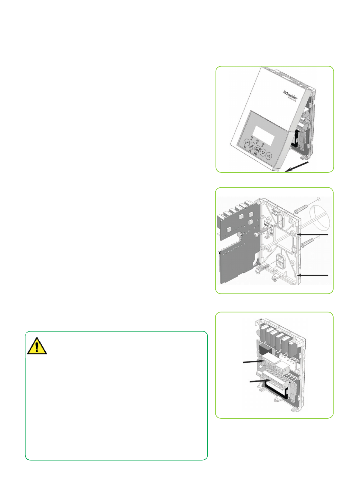
Preparation
• Remove security screw on bottom of Room Controller cover.
• Open unit by pulling on bottom side of Room Controller
(Figure 1).
• Remove wiring terminals from sticker.
• Read FCC ID and IC label installed in cover,
Installation
1. Swing open Room Controller PCB to left by pressing PCB locking tabs
(Figure 2).
2. Pull out cables 6” out from wall
(ensure wall surface flat and clean).
3. Insert cable in central hole of base.
4. Align base and mark location of two mounting holes on wall.
(ensure proper side of base up).
5. Install anchors in wall.
6. Insert screws in mounting holes on each side of base (Figure 2).
7. Gently swing back circuit board on base and push until tabs lock.
8. Strip each wire 1/4 inch from end.
9. Insert each wire according to wiring chart (page 3).
10. Gently push excess wiring back into hole (Figure 3).
11. Re-Install wiring terminals in correct locations (Figure 3).
12. Re-install cover (top side first) and gently push extra wire length back into
hole in wall.
13. Install security screw.
• If replacing an existing Room Controller, label wires before
removal of Room Controller.
• Electronic controls are static sensitive devices. Discharge
yourself properly before manipulating and installing Room
Controller.
• A short circuit or wrong wiring may permanently damage the
Room Controller or the equipment.
• All SE7000 series Room Controllers are designed for use as
operating controls only and are not safety devices. These
instruments have undergone rigorous tests and verification
prior to shipping to ensure proper and reliable operation in
the field. Whenever a control failure could lead to personal
injury and/or loss of property, it becomes the responsibility
of the user / installer / electrical system designer to
incorporate safety devices (such as relays, flow switch,
thermal protections) and/or an alarm system to protect the
entire system against such catastrophic failures. Tampering
with the devices or unintended application of the devices will
result in a void of warranty.
Figure-1 Open the cover
Figure-2 Location of PCB retaining tabs
Figure-3 Re-install terminal blocks
Page 3
Schneider Electric | II-SE76x7-A4.EN.12.2015.v2 December 2015
TERMINAL, IDENTIFICATION AND FUNCTION
Wiring
Part Number SE7657B5x45(X) SE7607B5x45(X)
Schedule Yes No
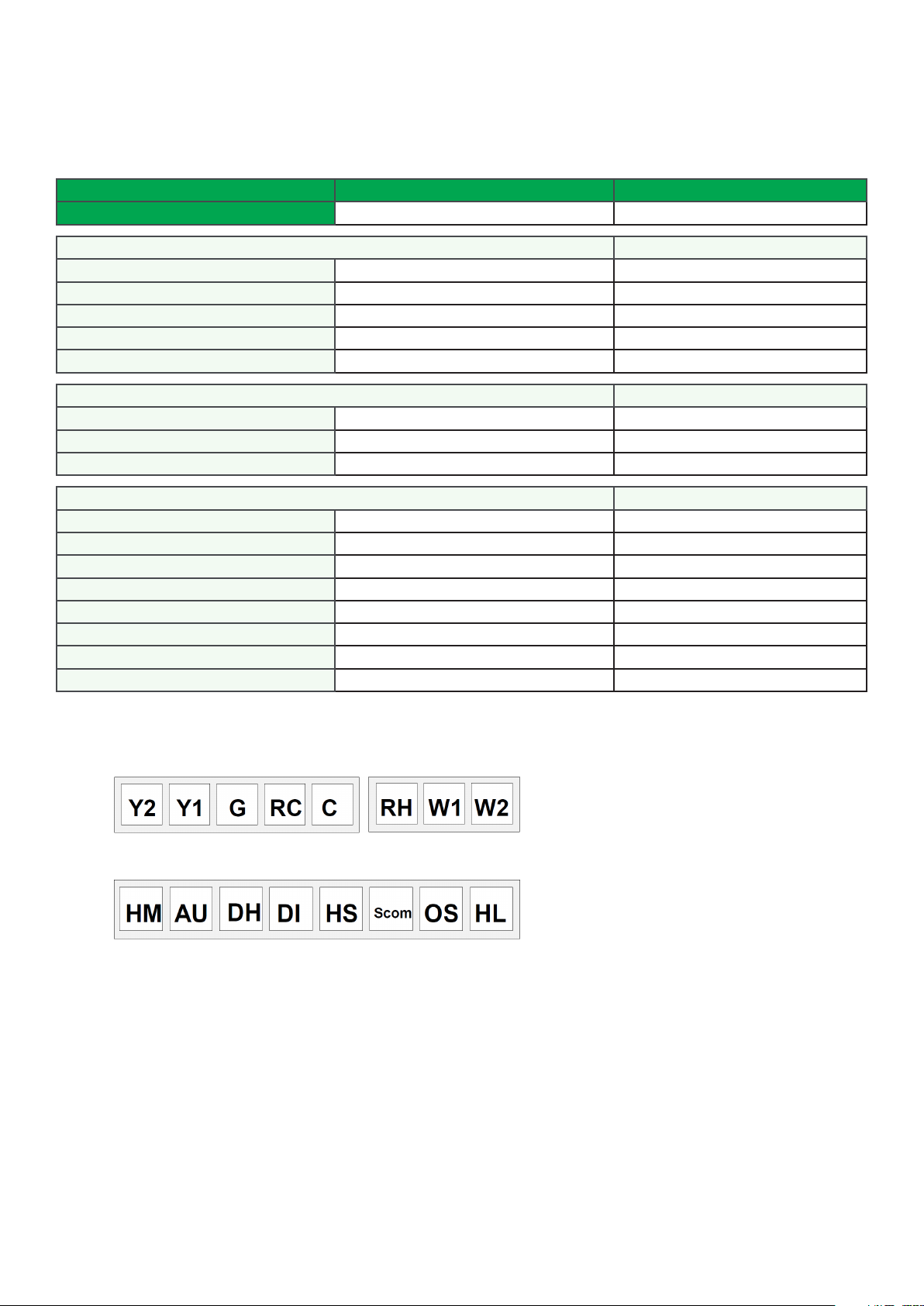
Top left terminal block
Y2 X X
Y1 X X
G X X
RC X X
C X X
Top right terminal block
RH X X
W1 X X
W2 X X
3
Bottom terminal block
HUM X X
AUX X X
DEHUM X X
DI X X
HS X X
SCOM X X
OS X X
HL X X
Screw terminal arrangement
5 pole left top connector 3 pole left top connector
8 pole bottom connector
MAIN OUTPUTS WIRING
Wiring notes:
Note 1: If the same power source is used for the heating stages, install jumper across RC and RH. Maximum current is 2.0 amps.
Note 2: If auxiliary output is used to toggle occupancy of the electronic control card inside the equipment, configure the relay
parameter (Aux cont) to the N.O. setting. A second relay can be added for additional functionality of the occupancy
output.
Note 3: Humidifier output uses a half bridge rectifier. Reference of the control signal is the common of the power supply of the
Room Controller. (Terminal C)
Note 4: Electromechanical contacts are to be used with the digital inputs. Electronic triacs cannot be used as mean of switching
for the input. The switched leg to the input for the input to activate is terminal C (common)
Note 5: The transformer of the unit provides power to the Room Controller and the additional loads wired to the Room Controller.
Page 4

Schneider Electric | II-SE76x7-A4.EN.12.2015.v2 December 2015
4
TYPICAL APPLICATIONS
Remote humidity sensor accessories
Wiring example of remote room
humidity sensor:
Wiring example of duct humidity
sensor:
Page 5

Schneider Electric | II-SE76x7-A4.EN.12.2015.v2 December 2015
User menu flow chart:
NOTE: Prompts may not all be present depending on model selected
5
Page 6

Schneider Electric | II-SE76x7-A4.EN.12.2015.v2 December 2015
6
CONFIGURATION AND STATUS DISPLAY INSTRUCTIONS
Status display
The Room Controller features a two-line, eight-character display. There is a low level backlight level that is always active and can
only be seen at night. When left unattended, the Room Controller has an auto scrolling display that shows the actual status of the
system.
Each item is scrolled one by one with the back lighting in low level mode. Pressing any key causes the back light to come on to
high level.
Manual scroll of each menu item is achieved by pressing the Yes (scroll) key repetitively. The last item viewed will be shown on the
display for 30 seconds before returning to automatic scrolling. Temperature is automatically updated when scrolling is held.
Sequence of auto-scroll status display:
ROOM
TEMPERATURE
x.x °C or °F
XX % RH
CLOCK STATUS SYSTEM MODE
Monday
12:00
Sys mode
auto Occupied
AM
Sys mode
off
Sys mode
cool
Sys mode
heat
Sys mode emer-
SCHEDULE
STATUS
OUTDOOR
TEMPERATURE
Outdoor
x.x °C or °F
ALARMS
Service
Occupied Hold Frost ON
Unoccup SetClock
Filter
Fan lock
gency
Outdoor air temperature
• Outdoor air temperature display is only enabled when outdoor air temperature sensor is connected.
• A maximum range status display of 50 °C (122 °F) indicates a shorted sensor. Associated functions, such as mode lockouts
and economizer function are automatically disabled.
• A minimum range status -40 °C (-40 °F) is not displayed and indicates a opened sensor or a sensor not connected. Associated functions, such as mode lockouts and economizer function are automatically disabled.
Alarms
• If alarms are detected, they will automatically be displayed at the end of the status display scroll.
• During an alarm message display, the back lit screen will light up at the same time as the message and shut off during the
rest of the status display.
• Two alarms maximum can appear at any given time.
• The priority for the alarms is as follows:
Frost On
SetClock
Service
Filter
Fan lock
Indicates that the heating is energized by the low limit frost protection room temperature setpoint 5.6 °C (42 °F)
Indicates that the clock needs to be reset. There has been a power
failure which has lasted longer than 6 hours
Indicates that there is a service alarm as per one of the configurable
digital input (DI1 or DI2)
Indicates that the filters are dirty as per one of the configurable
digital input (DI1 or DI2)
Indicates that the heating and cooling action are locked out due to a
defective fan operation
Page 7

Schneider Electric | II-SE76x7-A4.EN.12.2015.v2 December 2015
Three status LEDs on the Room Controller cover are used to indicate the status of the fan, a call for heat, or a call for cooling.
7
When any of the fans are ON, the FAN LED will illuminate
When heating is ON, the HEAT LED will illuminate
When cooling is ON, the COOL LED will illuminate
Multistage and single
LED
Operation
Heatpump models
SE76XXH
stage models
SE7600A, SE7652A,
SE7600B & SE7652B
Fan LED on When G Fan terminal
operates
Heating
LED on
When Y1 and or W1
terminal(s) operate in
When G Fan terminal
operates
When W1 terminal oper-
ates in heating mode
heating mode
Cooling
LED on
When Y1 terminal oper-
ate in cooling mode
When Y1 terminal oper-
ates in cooling mode
FAN
o
HEAT
o
COOL
o
Multistage
economizer models
SE7605B & SE7656B
When G Fan terminal
operates
When W1 terminal oper-
ates in heating mode
When Y1 terminal
operates in cooling
mode and / or
economizer output is in
function
Page 8

Schneider Electric | II-SE76x7-A4.EN.12.2015.v2 December 2015
8
USER INTERFACE
User configuring instructions menu
The SE76x7 series of Room Controller feature an intuitive, menu-driven, back-lit LCD display that
walks users through the configuring steps, making the configuring process extremely simple.
This menu is typically accessed by the user to set the parameters such as temperature and time
events, system mode, fan mode, etc.
It is possible to bring up the user menu at any time by depressing the MENU key. The status
display automatically resumes after exiting the user-configuring menu.
If the user pauses at any given time during configuring, Auto Help text is displayed to help and
guide the user through the usage and configuring of the Room Controller.
Press yes key to change cooling temperature setpoint
Ex.:
Use the up or down arrow to adjust cooling setpoint
Local keypad interface
Each section in the menu is accessed and configured using 5 keys on the Room Controller cover.
The priority for the alarms is as follows:
The YES key is used to confirm a selection, to move onto the next menu item
and to manually scroll through the displayed information.
The NO key is used when you do not desire a parameter change, and to advance to the next menu item. Can also be used to toggle between heating and
cooling setpoints.
The MENU key is used to access the Main User Menu or exit the menu.
The down arrow key is used to decrease temperature setpoint and to adjust
the desired values when configuring the Room Controller.
The up arrow key is used to increase temperature setpoint and to adjust the
desired values when configuring the Room Controller.
When left unattended for 45 seconds, the display will resume automatic status display scrolling.
To turn on the back light, press any key on the front panel. The back lit display will turn off when the Room Controller is left unattended for 45 seconds
Refer to SE7600 User Interface Guide on Schneider Electric Downloads Exchange for further details.
Page 9

Schneider Electric | II-SE76x7-A4.EN.12.2015.v2 December 2015
TROUBLESHOOTING GUIDE
Symptom Possible Cause Corrective Action
Check power supply voltage between C & RC to be from 19-
30 VAC Check for tripped fuse or circuit breaker
Verify that the transformer used is powerful enough (suf-
ficient VA’s) to supply all controlled devices including the
Room Controller
Change configuration parameter LOCKOUT to value “0” to
access all levels of the menu
1. The Room Controller needs to be in Permanent setpoint
mode for the new setpoint to be kept and memory and
used all the time
2. Go to the Set temperature menu.
3. The last prompt is setpoint type. Set it to Permanent
setpoint
Select Occupied Hold in Schedule hold or Override to force
the Room Controller Occupied heating setpoint
Wait, the anticycling period will end and the equipment will
1. Mode is locked out based on outside air temperature
2. Change configuration parameter H Lock to value 120 °F
( 49 °C ) to by-pass lockout
1. Start the Fan by forcing the Fan ON mode
2. Put a jumper across terminals RH & W1. The heating
should come ON. If it does not, verify wiring and check
if a jumper is required between RC & RH
Select Occupied Hold in Schedule hold or Override to force
the Room Controller Occupied cooling setpoint
Wait, the anticycling period will end and the equipment will
1. Mode is locked out based on outside air temperature
2. Change configuration parameter C Lock to value -40 °F (
-40 °C ) to bypass lockout
1. Start the Fan by forcing the Fan ON mode
2. Put a jumper across terminals RC & Y1.
The cooling should come ON. If it does not, verify wiring
1. Start the Fan by forcing the Fan ON mode
2. Put a jumper across terminals RC & G.
The fan should come ON. If it does not, verify wiring
No display on the
Room Controller
Keyboard menu
does not access all
functions
Temperature
setpoints revert
to original value
after a certain time
period
Room Controller
will not call for
heating
Room Controller
will not call for
cooling
The Room
Controller will not
turn on the fan
Absent or incorrect supply voltage
Overloaded power transformer
Keyboard locked
Temporary setpoint option selected
Wrong mode selected Select heating mode
Room Controller in Unoccupied mode
Anticycle delay active
Heating setpoint is satisfied Raise the Heating setpoint
Heating lockout
attained
Wiring error
Wrong mode selected Select cooling mode
Room Controller in Unoccupied mode
Anticycle delay active
Cooling setpoint is satisfied Lower the cooling setpoint
Cooling lockout attained
Wiring error
Wrong mode selected
Wiring error
9
start
start
Digital display
shows missing
digits or erratic
Defective display Replace Room Controller
segments
 Loading...