

Page 1
SE7600F Series
Installation Guide for RTU with Modulating Heat
CONTENTS
Installation 2
Location 2
Installation 2
Model Chart 3
Network ready 3
Terminal, Identification and Function 3
Screw terminal arrangement and wiring 3
Main outputs wiring 3
Typical Applications 4
Remote sensor accessories 4
Configuring and Status Display Instructions 6
Status display 6
User interface 7
User configuring instructions menu 7
Local keypad interface 7
Page 2
Schneider Electric | II-SE7600F-A4.EN.12.2015.v2 December 2015
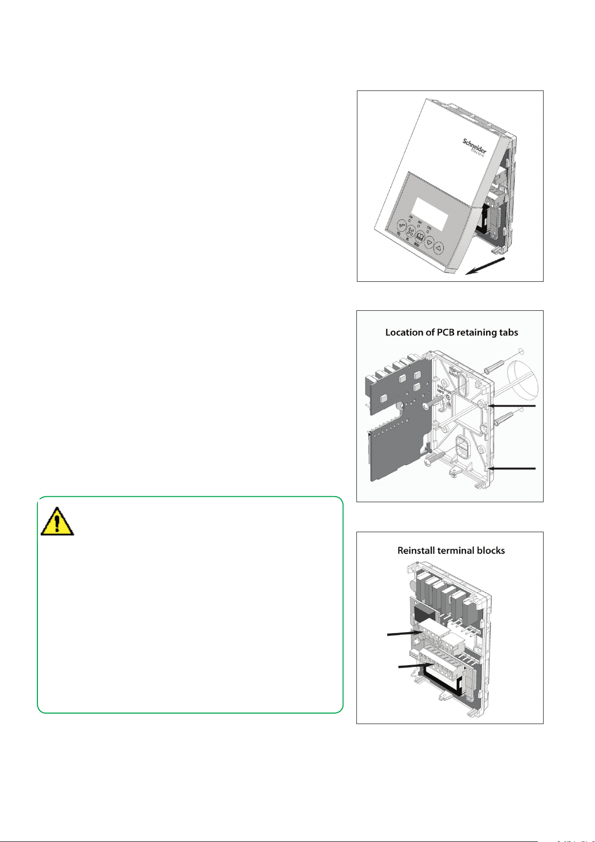
INSTALLATION
Inspection
• Remove security screw on bottom of Room Controller cover.
• Open unit by pulling on bottom side of Room Controller (Figure-1).
• Remove wiring terminals from sticker.
• Read the FCC ID and IC label installed in the cover.
Location
• Do not install on an outside wall.
• Install away from any direct heat source.
• Do not install near air discharge grill.
• Do not locate in direct sun radiation.
• Nothing should restrict vertical air circulation to Room Controller.
Installation
1. Swing open Room Controller PCB to the left by pressing two PCB
retaining tabs (Figure-2).
2. Pull cables 6" out from wall.
Ensure wall surface is flat and clean.
3. Insert cable into central hole of base.
4. Align base and mark location of two mounting holes on wall ensuring
proper side of base is upward.
5. Install screw anchors in wall.
6. Insert screws in mounting holes on each side of base (Figure-2).
7. Gently swing back circuit board on base and push until tabs lock.
8. Strip each wire 1/4 inch from end.
9. Insert each wire according to wiring diagram.
10. Gently push excess wiring back into hole in base.
11. Reinstall wiring terminals in correct locations (Figure-3).
12. Reinstall cover (top side first) and gently push any extra wire length back
into hole in wall.
13. Install security screw.
2
Figure-1 Ope ning the Cover
• If replacing an existing Room Controller, label wires before
removal of Room Controller.
• Electronic controls are static sensitive devices. Discharge
yourself properly before manipulating and installing Room
Controller.
• A short circuit or wrong wiring may permanently damage the
Room Controller or the equipment.
• All SE7000 series Room Controllers are designed for use as
operating controls only and are not safety devices. These
instruments have undergone rigorous tests and verification
prior to shipping to ensure proper and reliable operation in
the field. Whenever a control failure could lead to personal
injury and/or loss of property, it becomes the responsibility
of the user / installer / electrical system designer to
incorporate safety devices (such as relays, flow switch,
thermal protections) and/or an alarm system to protect the
entire system against such catastrophic failures. Tampering
with the devices or unintended application of the devices will
result in a void of warranty.
Figure-2 Op ening the PCB
Figure-3 Terminal Block Reinstall
Page 3
3
Schneider Electric | II-SE7600F-A4.EN.12.2015.v2 December 2015
NETWORK READY
• All Schneider Electric SE7600 series Room Controllers
(TEC) are designed for stand-alone (Network Ready) operation.
• They can be fully integrated into your choice of automation systems using
the available communication adapter options.
• If required, stand-alone (Network Ready) TECs can be field retrofitted with
the following communication adapters:
• VCM7000V5045W wireless Zigbee® communication adapter.
• VCM7600V5045B BACnet® MS-TP® communication adapter.
TERMINAL IDENTIFICATION
Terminal Use
1 – Y2 2nd cooling Y2 Second cooling stage output.
2 – Y1 1st cool Y1 First cooling stage output.
3 – G Fan G Fan output.
4 – RC 24VAC hot RC Power supply of thermostat, hot side.
5 – C 24VAC com C Power supply of thermostat, common side.
9 – AO analog heat AO Analog 0 – 10 VDC heating output.
10 – Auxiliary output AUX
11 – DI 1 DI 1
12 – DI 2 DI 2
13 – RS RS Remote temperature sensor input.
14 - Scom Scom Reference input for DI 1, RS, OS & DS.
15 - OS OS Outside air temperature sensor input.
16 - DS MS Discharge air temperature sensor input.
Terminal
Identification
Description
Auxiliary output used to disable economizer minimum
position or control lighting during unoccupied
periods.
Configurable extra digital input. See parameter
section for more information.
Configurable extra digital input. See parameter
section for more information.
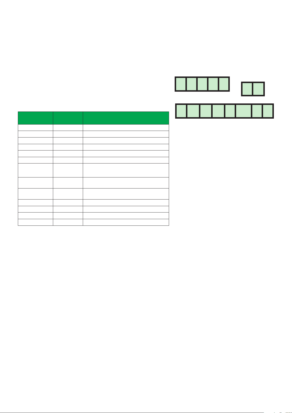
MAIN OUTPUTS WIRING
Screw Terminal Arrangement
SE76XXF Controller Terminals
Y2 Y1 G RC C
AO Aux DI1 DI2 RS Scom OS MS
Wiring Notes
Note 1
If the same power source is used for the heating
stages, install a jumper across terminals RC and RH.
The maximum current is 2.0 amps.
Note 2
If the auxiliary output is used to toggle occupancy
of the electronic control card inside the equipment,
configure the relay parameter (Aux cont) to the N.O.
setting. A second relay can be added for additional
functionality of the occupancy output.
Note 3
Economizer output uses a half-bridge rectifier.
Reference of the control signal is the Common
(Terminal C) of the power supply of the Room
Controller.
Note 4
Electromechanical contacts are to be used with the
digital inputs. Electronic triacs cannot be used as a
means of switching for the input. The switched leg
to the input for the input to activate is the Common
(Terminal C).
Note 5
The transformer of the unit provides power to the
Room Controller and the additional loads that will be
wired to the Room Controller.
Page 4

Schneider Electric | II-SE7600F-A4.EN.12.2015.v2 December 2015
TYPICAL APPLICATIONS
Digital Input #1
Main Outputs Wiring
4
Digital Input #2
Y2 Y1 GAOAU DI1 DI2 RS OS MSScom
Cool
Stage
2
Cool
Stage
1
RC C
Fan
T1
24V AC
REMOTE SENSOR ACCESSORIES
0-10 VDC
24V Com
Controller Wiring
System Wiring
Auxiliary
Output
Field
Contacts
Remote
Room
Sensor
Remote
Outdoor
Sensor
Remote
Mixed Air
Sensor
Applicable Models
Model Description Application Picture
• Remote room sensing
SE3010W1045 Room sensor
Room sensor
with temporary
SE3020W1045
override
key and
occupancy
LED
• 3 thermistors with 2 dip
switches are provided with
each sensor for various
averaging combinations
• Remote room sensing
with override key and
occupancy LED
• 3 thermistors with 2 dip
switches are provided with
each sensor for various
averaging combinations
Page 5

5
Schneider Electric | II-SE7600F-A4.EN.12.2015.v2 December 2015
D2 D1
One Sensor:
Two Sensors,
REMOTE TEMPERATURE SENSORS
Single Sensor
Scom
RS
AU
C
Two Sensor Averaging Application
Scom
RS
AU
C
D2 D1
Scom
RS
AU
C
D2 D1
Scom
RS
Three Sensor Application
Scom
RS
AU
C
D2 D1
Scom
RS
AU
C
D2 D1
SENSOR
SE3020W1045
Scom
RS
Aux
C
DI
SE3020W1045 SE3010W1045
Scom
RS
Aux
C
DI
SE3020W1045
Scom
RS
Aux
C
DI
SE3010W1045
Scom
RS
SE3020W1045 SE3010W1045
Scom
RS
Aux
C
DI
SE3020W1045 SE3020W1045 SE3010W1045
Scom
RS
Aux
C
DI
SE3010W1045
OR
Scom
RS
SE3020W1045
Scom
RS
Aux
C
DI
SE3010W1045
Scom
SE3010W1045
RS
Scom
RS
Scom
RS
Aux
C
DI
SENSOR
Scom
RS
SE3010W1045
Scom
RS
Scom
RS
Temp. Sensor DIP Switch Settings
ON
1
ON
1
SE3020W1045
Remote temperature sensor DIP switch location
S2-1 = ON
S2-2 = ON
2
Three Sensors:
S2-1 = OFF
S2-2 = OFF
2
ON
1
2
Temperature vs. resistance chart
for 10 Kohm NTC thermistor
ºC ºF Kohm
-40 -40 324.3197
-35 -31 234.4009
-30 -22 171.3474
-25 -13 126.6109
-20 -4 94.5149
-15 5 71.2430
-10 14 54.1988
-5 23 41.5956
0 32 32.1910
5 41 25.1119
10 50 19.7390
15 59 15.6286
20 68 12.4601
25 77 10.0000
30 86 8.0694
35 95 6.5499
40 104 5.3467
45 113 4.3881
50 122 3.6202
55 131 3.0016
(R
= 10KΩ±3%, B25/85°C = 3975K±1.5%)
25°C
averaging:
S2-1 = OFF
S2-2 = ON
Page 6

6
Schneider Electric | II-SE7600F-A4.EN.12.2015.v2 December 2015
CONFIGURING / STATUS DISPLAY
INSTRUCTIONS
Status Display
The Room Controller features a two-line, eightcharacter display. A low-level, always-active backlight can be seen only at night.
Left unattended, the Room Controller shows an
auto scrolling display that indicates the status of the
system. Each item is scrolled one by one with the
back lighting in low level mode. Pressing any key
will cause the back light to increase to high level.
Manual scrolling of each menu item is achieved by
pressing the YES (scroll) key repetitively. The last
item viewed will be shown on the display for 30
seconds before returning to automatic scrolling.
Temperature is automatically updated when scrolling is held.
Sequence of auto-scroll status display
CLOCK
STATUS
Monday
12:00 AM
SYSTEM
MODE
Sys Mode
Off
Sys Mode
Auto
Sys Mode
Cool
Sys Mode
Heat
SCHEDULE
STATUS
Occupied
OUTDOOR
TEMP.
Outdoor
x.x °C or °F
ALARMS
Service
Unoccupied DAS Alrm
Override SetClock
Filter
Fan lock
Frost ON
Alarms
• If alarms are detected, they will be displayed automatically at the end of the
status display scroll.
• During an alarm message display, the back lit screen will light up at the
same time as the message and shut off during the rest of the status display.
• Two alarms maximum can appear at any given time. The priority for the
alarms is as follows:
When any of the fan speeds are ON,
the FAN LED will illuminate.
When heating & reheat is ON, the
HEAT LED will illuminate.
When cooling is ON, the COOL LED
will illuminate.
Outdoor air temperature
• The outdoor air temperature display is only enabled when the outdoor air temperature sensor is
connected.
• A maximum range status display of 50 °C (122
°F) indicates a shorted sensor. Associated functions, such as mode lockouts and economizer
function are automatically disabled.
• A minimum range status -40 °C (-40 °F)
indicates an open-circuited sensor or a sensor
not connected. Associated functions, such as
mode lockouts and economizer function are
automatically disabled.
Frost ON
SetClock
Service
Filter
Fan lock
DAS
Alarm
Indicates that the heating is energized by the low limit frost
protection room temperature setpoint 5.6 °C (42 °F).
Indicates that the clock needs to be reset. There has been a power
failure which has lasted longer than 6 hours.
Indicates that there is a service alarm as per one of the configurable
digital inputs (DI1 or DI2).
Indicates that the filters are dirty as per one of the configurable
digital inputs (DI1 or DI2).
Indicates that the heating and cooling action are locked out due to a
fan malfunction.
Indicates that the discharge air temperature is either too low or too
high.
Page 7

7
Schneider Electric | II-SE7600F-A4.EN.12.2015.v2 December 2015
USER INTERFACE
User Configuring Instructions Menu
The SE76X6 series of Room Controller feature an
intuitive, menu-driven, back-lit LCD display that
walks users through the configuring steps, making the configuring process extremely simple. This
menu is typically accessed by the user to set the
parameters such as temperature and time events,
system mode, fan mode, etc...
It is possible to bring up the user menu at any time
by pressing the MENU key. The status display automatically resumes after exiting the user-configuring
menu.
If the user pauses at any given time during configuring, Auto Help text is displayed to help and guide
the user through the usage and configuring of the
Room Controller.
Local Keypad Interface
The YES key is used to confirm a selection, to move onto the
next menu item and to manually scroll through the displayed
information.
The NO key is used when you do not desire a parameter change,
and to advance to the next menu item. May also be used to
toggle between heating and cooling setpoints.
The MENU key is used to access the Main User Menu or
to exit the menu.
The DOWN ARROW key is used to decrease a temperature
setpoint and to adjust the desired values when configuring the
Room Controller.
The UP ARROW key is used to increase a temperature setpoint
and to adjust the desired values when configuring the Room
Controller.
Sequence of User Menu
OVERRIDE
RESUME
Override
schd? Y/N
(Appears only in
unoccupied mode)
Cancel
ovrd? Y/N
(Appears only in
override mode)
SYSTEM MODE
SETTING
Sys mode
set? Y/N
SCHEDULE
SETTING
Schedule
set? Y/N
CLOCK SETTING
Clock
set? Y/N
Example: Press the YES key to change the cooling
temperature setpoint. Use the Up/Down Arrow keys
to adjust the cooling setpoint.
Each of the sections in the menu is accessed and
configured using 5 keys on the Room Controller
cover.
When left unattended for 45 seconds, the display
will resume automatic status display scrolling.
To turn on the back light, press any key on the front
panel. The back light will turn off when the Room
Controller is left unattended for 45 seconds.
Page 8

8
Schneider Electric | II-SE7600F-A4.EN.12.2015.v2 www.schneider-electric.com/buildings December 2015
 Loading...