

Page 1
Schneider Electric | II-SE730 0F-A4.EN.12.2015.v2 December 2015
PIR Ready SE7300F5x45X-ECM Series
Installation Guide for Commercial and Lodging FCU Applications
1
CONTENTS
Installation 2
Location 2
Installation 2
Features overview 3
Model Selection 3
Terminal, Identification and Function 3
Wiring 4
Screw terminal arrangement 4
Main outputs wiring 4
Remote mount temperature sensors 4
Configuring and Status Display Instructions 6
Status display 6
User Interface 7
Page 2
Schneider Electric | II-SE730 0F-A4.EN.12.2015.v2 December 2015
INSTALLATION
•
Remove security screw on bottom of Room Controller cover.
•
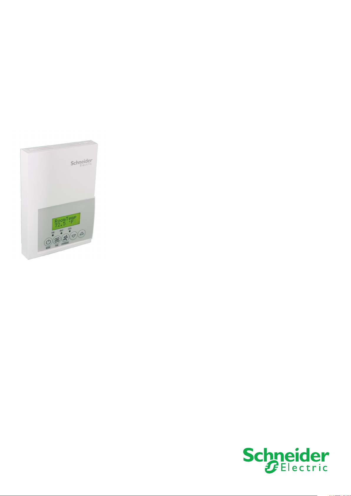
Open unit by pulling on bottom side of Room Controller (Figure 1).
• Remove wiring terminals from sticker.
• Read FCC ID and IC label installed in cover.
Location
1. Should not be installed on outside wall.
2. Must be installed away from any direct heat source.
3. Should not be installed near air discharge grill.
4. Should not be affected by direct sun radiation.
5. Nothing should restrict vertical air circulation to Room Controller.
Installation
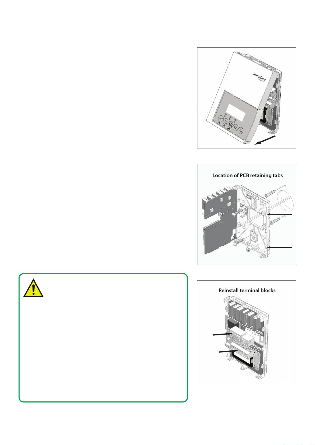
1. Swing open Room Controller PCB to left by pressing PCB locking tabs
(Figure 2).
2. Pull out cables 6” out from wall. Ensure wall surface is flat and clean.
4. Insert cable in central hole of base.
5. Align base and mark location of two mounting holes on wall ensuring
proper side of base is up.
6. Install anchors in wall.
7. Insert screws in mounting holes on each side of base (Figure 2).
8. Gently swing back circuit board on base and push until tabs lock.
9. Strip each wire 1/4 inch from end.
10. Insert each wire according to wiring diagram (page 3).
11. Gently push excess wiring back into hole (Figure 3).
12. Re-Install wiring terminals in correct locations (Figure 3).
13. Re-install cover (top side first) and gently push extra wire length back into
hole in wall.
14. Install security screw.
2
Figure-1 Ope ning the Cover
•
When replacing an existing Room Controller, label the wires
before removal of the Room Controller.
•
Electronic controls are static sensitive devices. Discharge
yourself properly before manipulating and installing the Room
Controller.
•
A short circuit or wrong wiring may permanently damage the
Room Controller or the equipment.
•
All SE7000 series Room Controllers are designed for use as
operating controls only and are not safety devices. These
instruments have undergone rigorous tests and verification
prior to shipping to ensure proper and reliable operation in
the field. Whenever a control failure could lead to personal
injury and or loss of property, it becomes the responsibility of
the user / installer / electrical system designer to incorporate
safety devices (such as relays, flow switch, thermal protections,
etc…) and or an alarm system to protect the entire system
against such catastrophic failures. Tampering with the devices
or unintended application of the devices will result in a void of
warranty.
Figure-2 Op ening the PCB
Figure-3 Terminal Block Reinstall
Page 3
Schneider Electric | II-SE730 0F-A4.EN.12.2015.v2 December 2015
3
Wa
osition
t
Hot/Cold
MODEL SELECTION
Part number Description Communication Options
SE7300F5x45-ECM Commercial Applications with Override Communication Ready
SE7300F5x45B-ECM Commercial Applications with Override BACnet MS/TP
SE7305F5x45-ECM °C/°F Hotel/Lodging Applications Communication Ready
SE7305F5x45B-ECM °C/°F Hotel/Lodging Applications BACnet MS/TP
• Controllers can be ordered with a factory installed PIR cover. Please use (5545)
extension instead of the (5045) only extension. Ex. SE7300F5545B-ECM.
• Controllers ordered without a PIR cover can be retrofitted with a separate
PIR accessory cover afterwards when required
TERMINAL, IDENTIFICATION AND FUNCTION
1- Not used
2- Not used
3- Fan Enable/disable
4- 24 V~ Hot
5- 24 V~ Com
6- Aux BO 5
7- Aux BO 5
8- Blank
9- ECM Output
10-Valve Output
11- Not used
12- BI #1
13- RS
14- Scom
15- BI # 2
16- UI # 3 COS / COC /SS
Fan H
Fan M
Fan L
24 V~ Hot
24 V~ Com
BO 5-Aux
BO 5-Aux
Blank
AO 2
AO 1
Blank
BI 1
RS
Scom
BI 2
UI 3
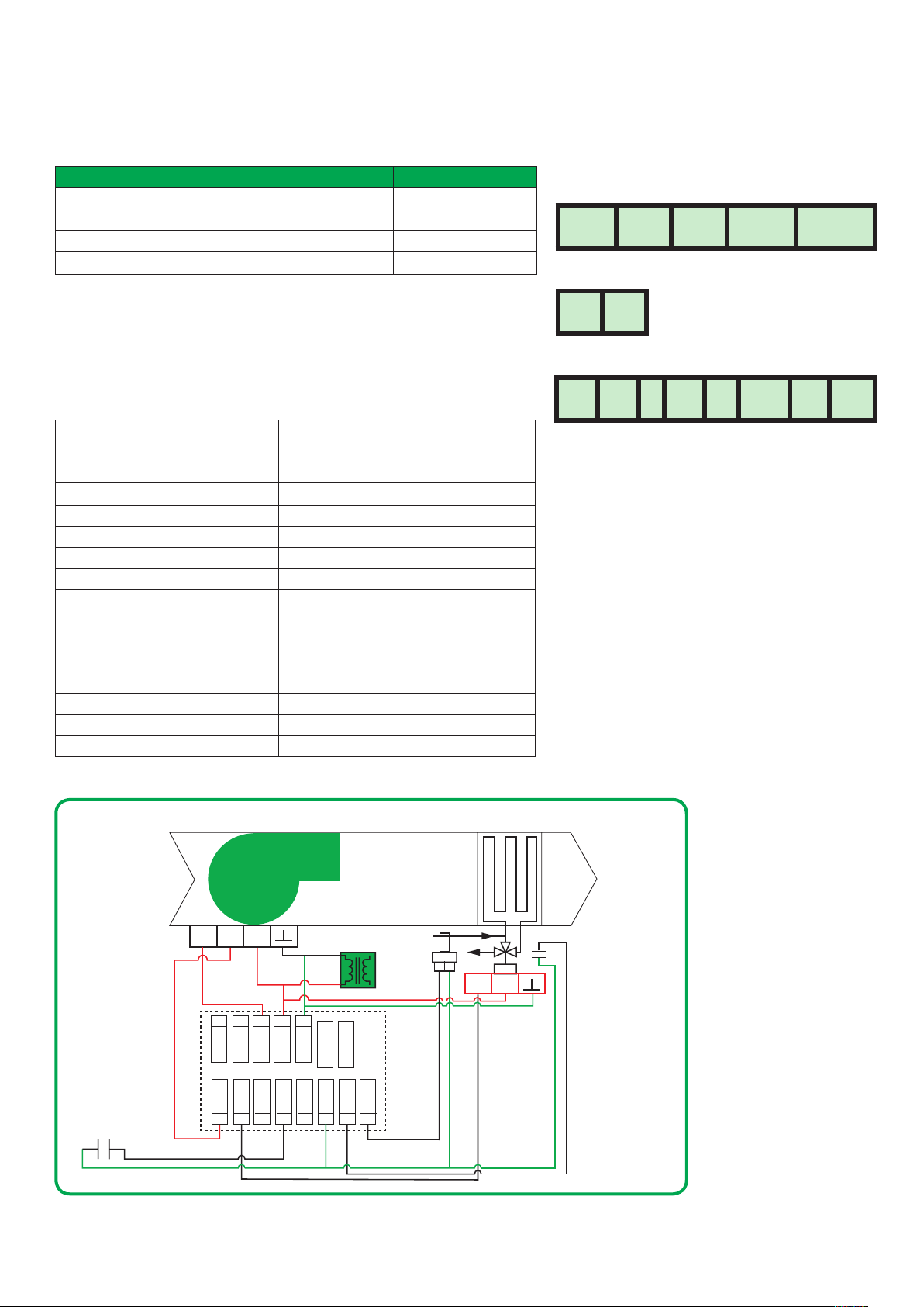
Screw terminal arrangement and wiring
5 pole left top connector
FAN H FAN M FAN L 24V~Hot 24V-Com
3 pole right top connector
BO5 BO5
8 pole left top connector
AO2 AO1 BI1 RS Scom B12 UI3
Main outputs wiring
Wiring notes:
Note 1
Electromechanical contacts are to be used with the
digital inputs. Electronic triacs cannot be used as
mean of switching for the input. The switched leg
to the input for the input to activate is terminal C
(common).
Note 2
The transformer of the unit provides power to the
Room Controller and the additional loads that will be
wired to the Room Controller.
Wiring
ter Detector
(NO contact)
On/
O
2-10
Vdc24Vac
2
1
Fan-H
Fan-M3Fan-L
AO210AO1
9
4
24V-Hot
BI1
12
5
24V-Com
13RS14
Transformer
6
B05
Scom
24Vac
7
B05
BI2
15
UI3
16
Water
Supply
Sensor
Water Coil
0-10
Vdc24Vac
(Valve Open P
Detector) NO Contac
Page 4

Schneider Electric | II-SE730 0F-A4.EN.12.2015.v2 December 2015
4
BI 2
One Sensor:
Two Sensors,
Remote mount temperature sensors use 10K type 2 NTC thermistors
• Each sensor can be configured for various averaging combinations
• Optional occupancy led
• Optional override key
Single Sensor Averaging Application
Scom
RS
BO5
24 Vac Com
BI 2
SE3020W1045
Scom
RS
Aux
C
DI
Two Sensor Averaging Application
Scom
SE3010W1045 SE3020W1045
Scom
RS
BO5
24 Vac Com
BI 2
OR
RS
Aux
C
DI
SE3010W1045
Scom
RS
Scom
RS
Temp. Sensor DIP Switch Settings
ON
1
ON
1
SE3020W1045
Remote temperature sensor DIP switch location
S2-1 = ON
S2-2 = ON
2
Three Sensors:
S2-1 = OFF
S2-2 = OFF
2
ON
averaging:
S2-1 = OFF
S2-2 = ON
1
2
Scom
RS
BO5
24 Vac Com
SE3020W1045
Scom
RS
Aux
DI
BI 2
Scom
RS
SE3010W1045
Scom
RS
Three Sensor Averaging Application
Scom
RS
BO5
24 Vac Com
Scom
RS
SE3010W1045 SE3010W1045
Scom
RS
Aux
C
DI
SE3010W1045 SE3010W1045 SE3010W1045
Scom
RS
SE3020W1045
Scom
Notes for averaging applications:
RS
Aux
C
C
DI
• SE3010W1045 and SE3020W1045 can be mixed
matched.
• SE3010W1045 and SE3020W1045 are to be
wired in parallel.
• Respect the dip switch setting in each remote
sensor.
SE3010W1045
Scom
S3010W1045
RS
SE3020W1045
Scom
RS
Scom
RS
Scom
RS
Scom
RS
Page 5

Schneider Electric | II-SE730 0F-A4.EN.12.2015.v2 December 2015
Temperature vs. Resistance Chart for 10K Type 2 NTC Thermistor
(R
= 10KΩ±3% - B
25°C
25/85°C
5
= 3975K±1.5%)
ºC ºF Kohm
-40 -40 324.3197
-39 -38 303.6427
-38 -36 2 8 4.418 9
-37 -35 266.5373
-36 -33 249.8958
-35 -31 234.4009
-34 -29 219.9666
-33 -27 206.5140
-32 -26 19 3.9703
-31 -24 182.2686
-30 -22 171. 3474
-29 -20 16 1.14 9 9
-28 -18 151. 623 9
-27 -17 142.7 2 11
-26 -15 134.3971
-25 -13 126 .610 9
-24 -11 119.324 4
-23 -9 112. 50 2 8
-22 -8 10 6.113 5
-21 -6 10 0 .12 6 8
ºC ºF Kohm
-20 -4 9 4. 514 9
-19 -2 89.2521
-18 0 84.3147
-17 1 79.6808
-16 3 75.3299
-15 5 71. 24 3 0
-14 7 6 7. 4 02 8
-13 9 63.7928
-12 10 60.3980
-11 12 5 7. 20 4 4
-10 14 5 4 .1 9 8 8
-9 16 51. 3 692
-8 18 48.70 42
-7 19 46.1933
-6 21 43.8268
-5 23 41.5 956
-4 25 39.4921
-3 27 3 7. 5 0 5 6
-2 28 35.6 316
-1 30 33.8622
ºC ºF Kohm
0 32 3 2 .191 0
1 34 30. 612 0
2 36 2 9 .1197
3 37 2 7. 7 0 8 8
4 39 2 6 . 3 74 4
5 41 2 5 .1119
6 43 2 3.9172
7 45 22.7861
8 46 21.7151
9 48 20.700 4
10 50 19.7390
11 52 18.8277
12 54 17. 9 63 6
13 55 17.14 4 0
14 57 16 .36 65
15 59 15.6 28 6
16 61 14. 928 0
17 63 14 .26 2 9
18 64 13.6 310
19 66 13.0307
ºC ºF Kohm
20 68 12.4 601
21 70 11.9177
22 72 11. 4 0 18
23 73 10 . 9112
24 75 10.4443
25 77 10.0000
26 79 9.5754
27 81 9 .1711
28 82 8.786 0
29 84 8.4190
30 86 8.0694
31 88 7.7 3 6 0
32 90 7. 41 8 2
33 91 7.115 0
34 93 6.8259
35 95 6.5499
36 97 6.2866
37 99 6.0 3 51
38 10 0 5.7950
39 102 5.5657
ºC ºF Kohm
40 10 4 5.3467
41 10 6 5.1373
42 108 4.9373
43 10 9 4 .746 0
44 111 4.5631
45 113 4.3881
46 115 4.2208
47 117 4.0607
48 118 3 .9 074
49 120 3.7607
50 12 2 3.6202
51 124 3.4857
52 126 3.3568
53 127 3.2333
54 12 9 3 .115 0
55 131 3.0016
56 13 3 2.8928
57 135 2.788 6
58 13 6 2.6886
59 138 2.5926
Page 6

Schneider Electric | II-SE730 0F-A4.EN.12.2015.v2 December 2015
6
CONFIGURING AND STATUS DISPLAY INSTRUCTIONS
Status display
The Room Controller features a two-line, eight-character display. There is a low
level backlight that is always active and can only be seen at night.
When left unattended, the Room Controller has an auto scrolling display that
shows the current status of the system.
Each item is scrolled sequentially with the back lighting in low level mode.
Pressing any key will cause the back light to come on to high level.
Manual scrolling of each menu item is achieved by pressing the Yes (scroll) key
repetitively. The last item viewed will be shown on the display for 30 seconds
before returning to automatic scrolling. Temperature is automatically updated
when scrolling is held.
Sequence of auto-scroll status display
CLOCK
STAT U S
Monday
12: 00 AM
SYSTEM
MODE
Sys Mode
Auto
Sys Mode
Cool
Sys Mode
Heat
Sys Mode
Off
SCHEDULE
STAT U S
Occupied
Stand-by
OUTDOOR
TEMP.
Outdoor
x.x °C or °F
Network
value only
ALARMS
Service
Filter
Unoccup Window
Overrride
Three status LED’s on the Room Controller cover are
used to indicate the status of the fan (any speed), a
call for heat, or a call for cooling.
Fan coil models
When any of the fan speeds are ON,
the FAN LED will illuminate.
When heating is ON, the HEAT LED
will illuminate.
When cooling is ON, the COOL LED
will illuminate.
Outdoor air temperature
• Display is only enabled when outdoor air temperature network variable is
received.
Occupancy status
• Occupied, Stand-By, Unoccupied and Override status are displayed on the
scrolling display.
Alarms
• If alarms are detected, they will automatically be displayed at the end of the
scrolling status display.
• When an alarm message is displayed, the backlit screen will illuminate at the
same time as the message and shut off during the rest of the status display.
• A maximum of two alarms can appear at any given time. The priority for the
alarms are as follows:
Service
Filter
Window
Indicates that there is a service alarm as per one of the configurable
digital input.
Indicates that the filters are dirty as per one of the configurable
digital input.
Indicates that the outside window or door is opened and that the
Room controller has cancelled any cooling or heating action.
Page 7

Schneider Electric | II-SE730 0F-A4.EN.12.2015.v2 December 2015
USER INTERFACE
Hotel/Lodging Models Commercial Models
Unoccupied mode override
An Override can be made on commercial models during an unoccupied
period. If the Override option is enabled in the lockout configuration, pressing
the middle override button will resume occupied setpoints for a time specified
by the parameter “ToccTime”.
7
Local Keypad Interface
Each of the sections in the menu is accessed and configured using 5 keys on
the Room Controller cover.
MODE Is used to toggle between the different system modes
available as per sequence and menu selected.
• Repetitively pressing the button will toggle between all the
available modes.
•
Available menus are dependent on selected sequence of
operation
FAN Is used to toggle between the different fan modes available
as per the sequence and menu selected
• Repetitively pressing the button will toggle between all the
available modes
• Available menus are dependent on selected sequence of
operation and menu selected for Fan
Hotel and lodging applications. Toggles the local user
temperature scale between °F and °C
Commercial and institutional applications. Set a local unoccupied
timed OVERRIDE to occupied mode
• In cooling mode only the cooling setpoint is displayed,
• In heating mode only the heating setpoint is displayed
• In auto mode, (See below)
• In cooling mode only the cooling setpoint is displayed,
• In heating mode only the heating setpoint is displayed
• In auto mode, (See below)
• Any setpoint change can be permanent or temporary based on
configuration parameter (Setpoint Type)
• Any setpoint written through the network, will be permanent and cancel any
active temporary setpoints
• Lockouts of access to certain functions is made with configuration
parameter (lockout)
Page 8

Schneider Electric | II-SE730 0F-A4.EN.12.2015.v2 December 2015
 Loading...