

Page 1
SmartStruxure Lite
Solution
SE7000/SE8000 Room Controllers
ZigBee Pro Wireless Integration Guide
Get Control. Get Efficient. Get Value
Page 2

SE7000/SE8000 Room Controllers ZigBee Pro Wireless Integration Guide
Schneider Electric | IG-SE7000SE8000ZP-A4.EN.03.2014.v2 March 2014
Table of Contents
Who Should Read this Page .................................................................................................................................. 3
Preparation ................................................................................................................................................................ 3
About this Guide ....................................................................................................................................................... 3
Overview ..................................................................................................................................................................... 3
Multi-purpose Manager ........................................................................................................................................... 4
MPM-UN ..................................................................................................................................................................... 4
MPM-GW .................................................................................................................................................................... 4
MPM-VAV .................................................................................................................................................................... 5
Room Comfort Controllers ..................................................................................................................................... 5
SE7000 Series / SE8000 Series ........................................................................................................................... 5
ZigBee Pro ................................................................................................................................................................. 6
Addresses .................................................................................................................................................................. 6
ZigBee Pro Protocols .............................................................................................................................................. 6
ZigBee Topology ....................................................................................................................................................... 6
ZigBee Security ........................................................................................................................................................ 6
Network Key .............................................................................................................................................................. 7
Trust Center ............................................................................................................................................................... 7
Trust Center Link Keys ............................................................................................................................................ 7
Distribution of the Network Key ............................................................................................................................ 7
Wireless Mesh Networks ........................................................................................................................................ 7
Design and Deployment .......................................................................................................................................... 7
Deployment Tool ....................................................................................................................................................... 7
Working with ZigBee Pro ........................................................................................................................................ 8
Network Layer ........................................................................................................................................................... 8
Extended PAN ID (EPID) ......................................................................................................................................... 8
Channels ................................................................................................................................................................... 8
Router, End Device, Coordinator, Trust Center ................................................................................................. 8
Broadcasting ............................................................................................................................................................. 8
Security and Trust Center ...................................................................................................................................... 8
Network Key .............................................................................................................................................................. 8
Application Link Keys .............................................................................................................................................. 8
Trust Center Link Keys ............................................................................................................................................ 9
Joining a Network .................................................................................................................................................... 9
Application Layer...................................................................................................................................................... 9
Endpoint ..................................................................................................................................................................... 9
Cluster .......................................................................................................................................................................10
Supported Cluster ...................................................................................................................................................10
Attributes Supported in Specified Clusters for Thermostat Clusters .........................................................10
Attributes ..................................................................................................................................................................13
Reporting ...................................................................................................................................................................13
Applications in ZigBee Pro ....................................................................................................................................14
Sensors and Aggregator ........................................................................................................................................14
Sensor and Actuator ...............................................................................................................................................14
Client and Server .....................................................................................................................................................14
Gateway and Proxy .................................................................................................................................................14
ZigBee Network Diagrams .....................................................................................................................................15
2
Page 3

SE7000/SE8000 Room Controllers ZigBee Pro Wireless Integration Guide
Schneider Electric | IG-SE7000SE8000ZP-A4.EN.03.2014.v2 March 2014
ZigBee Pro Network ..............................................................................................................................................15
ZigBee Pro Message Flow .....................................................................................................................................15
Design Considerations ..........................................................................................................................................16
Integrate ZigBee Pro with Room Controller and Manager .............................................................................17
Online Room Controller Database Creation with Live Integration Binding Onsite ...................................17
Offline Room Controller Database Creation with Onsite Room Controller Integration Binding ............ 17
Room Controller or Manager Replacement in Field ........................................................................................17
Configuration ............................................................................................................................................................17
Integration .................................................................................................................................................................18
Integration with Manager using Building Expert ..............................................................................................18
Binding .......................................................................................................................................................................18
Setting Device Data Points ...................................................................................................................................19
Change of Values ................................................................................................................................................... 20
Procedures - Integrate Room Controller and Manager ..................................................................................21
Procedure - Configure SE7200, SE7300, SE7600 and SER7300 Series ...................................................21
Procedure - Configure SE8000 Series ...............................................................................................................21
Procedure - Login to Manager ............................................................................................................................ 22
Procedure - Configure Manager ..........................................................................................................................23
Procedure - Add Device ........................................................................................................................................24
Procedure - Bind and Configure ZigBee Pro Online for 7000 Series .........................................................24
Procedure - Assign Device Data Points ............................................................................................................. 26
Procedure - Configure ZigBee Pro Offline for SE7000 Series ...................................................................... 27
Configure ZigBee Pro Online for SE8000 Series ............................................................................................. 27
Procedure - Configure Points and Change of Values for 8300 Series ....................................................... 27
Procedure - Configure ZigBee Pro Offline for 8300 Series ........................................................................... 27
Object Tables ........................................................................................................................................................... 28
Objects Supported By Models SE7200 and SE7300 Series ......................................................................... 28
Objects Supported By Models SE7600 Series ................................................................................................. 29
Objects Supported By Models SE7300 Controllers ........................................................................................ 32
Objects Supported By Models SE7000 Zoning Products .............................................................................. 32
List of Property Numeric Values Range Restrictions ...................................................................................... 36
List of Property Enumeration Sets for BV Objects .......................................................................................... 37
List of Property Enumeration Sets for MV Objects ......................................................................................... 39
SE8000 ZigBee Parameter Details ...................................................................................................................... 45
Device Object Table ................................................................................................................................................ 46
Analog Outputs Properties .................................................................................................................................... 46
Analog Hardware Values Properties .................................................................................................................... 47
Binary Input Properties .......................................................................................................................................... 47
Binary Output Properties ....................................................................................................................................... 47
Binary Values Properties ....................................................................................................................................... 48
CSV Properties ........................................................................................................................................................ 48
Multistate Properties .............................................................................................................................................. 48
Analog Inputs Properties ....................................................................................................................................... 49
SE8000 Series.......................................................................................................................................................... 49
SE720xx Integration – Graphic User Interface (GUI) objects ....................................................................... 51
SE73xxX Integration – Graphical User Interface (GUI) Objects.................................................................... 52
SE8000X Integration – Graphical User Interface (GUI) Objects ................................................................... 53
SE8000X Integration – Graphical User Interface (GUI) Objects ................................................................... 53
Tips and Things You Need To Know ................................................................................................................... 54
3
Page 4

SE7000/SE8000 Room Controllers ZigBee Pro Wireless Integration Guide
Schneider Electric | IG-SE7000SE8000ZP-A4.EN.03.2014.v2 March 2014
Who Should Read this Guide
This guide is for integrators of SmartStruxure™ Lite solutions. It provides important information for getting you started with the
set-up and configuration of your building efficiency management system.
Ensure you follow the instructions to ensure a successful and trouble-free installation at the client’s site.
Plan and Prepare
The information contained here helps you work effectively and minimizes the likelihood of any critical issues occurring during
installation. Successful integration of your SmartStruxure Lite system requires proper preparation and planning. Planning in
advance saves resources, prevents wasted effort, and saves time and money for you and your customer.
About this Guide
This guide provides instructions for the physical integration of a SER7000/SE8000 Series model the with the following
Multi-purpose Manager (MPM):
• MPM-UN
• MPM-VA VAV
• MPM-GW
For more information visit our website at www.documentation.smartstruxurelite.com
Overview
This guide focuses on full integration of Multi-purpose Managers (MPM) and Room Controller with a built in Wireless Controller
Driver Card in a ZigBee Pro adapter environment.
4
Page 5
SE7000/SE8000 Room Controllers ZigBee Pro Wireless Integration Guide
Schneider Electric | IG-SE7000SE8000ZP-A4.EN.03.2014.v2 March 2014
Multi-purpose Manager
Multi-purpose Manager (MPM) Devices are flexible lines of site and zone Managers. They allow you to install and manage
integrated solutions for HVAC, lighting, and metering. They are also a quick and efficient link between multiple devices based on
many standard protocols.
The Building Expert web building energy management system is embedded in MPM Devices.
Multi-purpose Managers are fully programmable and are designed with wireless lighting and HVAC applications in mind. They can
also be used to control a wide range of ZigBee Pro compatible devices such as light sensors, light switches, relays, thermostats,
card readers, and magnetic door contacts.
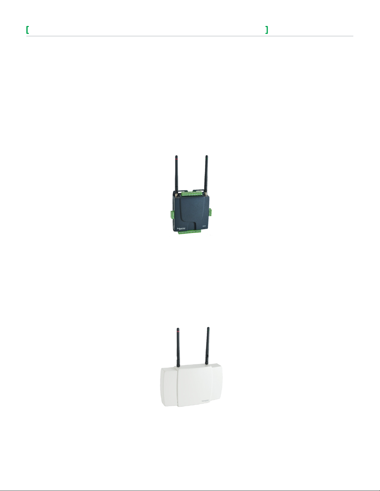
MPM-UN
The MPM-UN is an electronic device designed to monitor and control various devices for building automation applications. The
Manager consists of a printed circuit board housed in a plastic shell casing.
5
5
External connectors are available for the following:
• 6 universal inputs
• 4 analog outputs
• 2 binary outputs (dry contact)
• LAN (Ethernet cable)
• RS-485 device (Modbus)
• CANbus
• Power supply
The device has wireless modules to enable bidirectional communication with ZigBee Pro devices. Managers can communicate
with each other wirelessly using their ZigBee Pro modules.
MPM-GW
The MPM-GW wireless Manager is an electronic device designed to integrate wireless solutions to wired building automation
systems.
Small buildings system gateways can integrate wireless devices based on ZigBee Pro protocols and standards into building
automation systems.
The MPM-GW is a printed circuit board housed in a plastic shell casing. Unlike the MPN-UN and MPM-VA, there are no physical
(wired) I/Os on this Manager.
Page 6
SE7000/SE8000 Room Controllers ZigBee Pro Wireless Integration Guide
Schneider Electric | IG-SE7000SE8000ZP-A4.EN.03.2014.v2 March 2014
The following connectors are concealed in a casing:
• LAN
• CANbus
• Power supply
The MPM-GWs have embedded ZigBee Pro wireless modules to enable bidirectional communication with ZigBee Pro devices. The
Managers can also communicate with each other wirelessly using their ZigBee Pro modules.
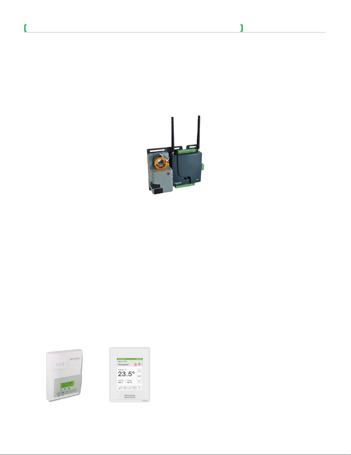
MPM-VAV
The MPM-VAV Manager is designed to monitor and control various devices for building automation purposes, including VAV
boxes. It can also control various devices for building automation applications.
6
External connectors are available for the following:
• 6 universal inputs
• 4 analog outputs
• 2 binary outputs (dry contact)
• 1 damper actuator
• 1 pressure sensor
• LAN (Ethernet cable)
• RS-485 device (Modbus)
• CANbus
• Power supply
The device has a pressure sensor and is equipped with an optional damper actuator. The device also has optional embedded
EnOcean and ZigBee Pro wireless modules to enable bidirectional communication with their respective protocol. The Managers
can communicate with each other wirelessly using their ZigBee Pro modules.
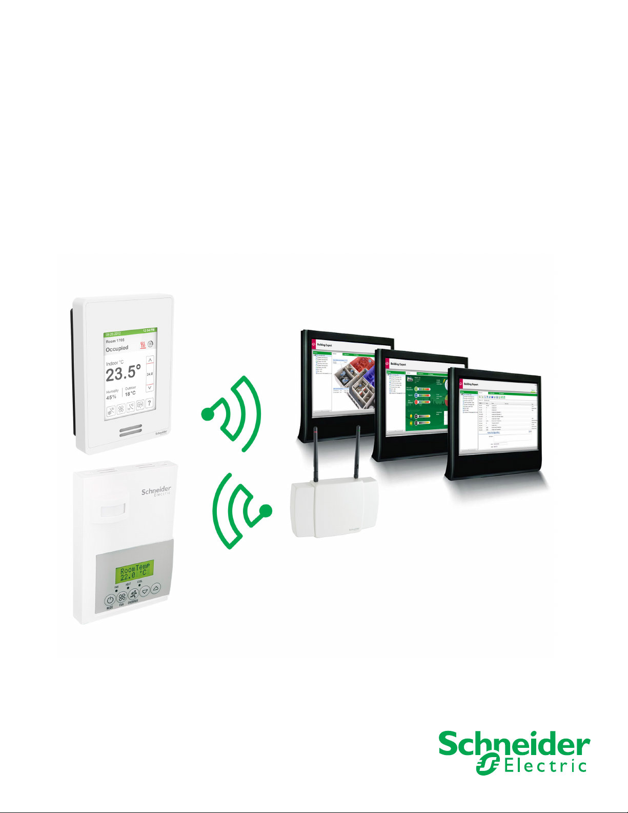
Room Comfort Controllers
The Room Comfort Controller allows for simple management of multiple equipment controllers from one convenient location.
The device is compatible with terminal equipment controllers including fan-coil units, rooftop units, and heat-pump models. You
can also adjustment set points, central system modes, global overrides, broadcasting of outdoor temperature, and central alarm
reporting.
The wireless communication card can be separately installed in the Room Controller for use with Schneider Electric MPM
Controllers. The communication card and associated wireless communicating controllers encourages the use of existing wiring
utilized by existing electronic Controller type controls.
SE7000 Series SE8000 Series
Page 7

SE7000/SE8000 Room Controllers ZigBee Pro Wireless Integration Guide
Schneider Electric | IG-SE7000SE8000ZP-A4.EN.03.2014.v2 March 2014
ZigBee Pro Overview
ZigBee Pro is a specification for a suite of high level communication protocols used to create personal area networks built from
small, low-power devices. Though low-powered, ZigBee Pro devices often transmit data over longer distances by passing data
through intermediate devices to reach more distant ones. This is accomplished by creating a mesh network, such as a network
with no centralized control or high-power transmitter/receiver able to reach all of the networked devices.
ZigBee Pro is a standard which is suitable for wireless sensor and controller networks. In ZigBee Pro, a device, node, or
Controller is determined to have joined a network if it can obtain a ZigBee Pro network address from a parent device, provided
it passes the necessary security protocols. This ZigBee Pro address is a value which is not initially exposed or available for the
integrator to see.
Devices, nodes, and Controllers can calculate and assign addresses for their surrounding devices by a distributed address
assignment scheme. This assignment is flexible, but it does somewhat restrict the number of attached devices and the possible
depth of the said network for any given device on the network.
ZigBee Pro is a mesh type network. The ZigBee Pro coordinator, or MPM with wireless communication card, is responsible for
initializing, maintaining, and controlling the network. For mesh networks, devices communicate with each other in a multi-hop
fashion. The network is formed by one ZigBee Pro coordinator and extended by multiple ZigBee Pro routers. A device can join a
network as an end device by associating with the coordinator or a router.
A ZigBee Pro network typically has the following three types of devices:
• ZigBeeProCoordinator:heart of the network. There must be one and only one coordinator per network. Its role is to act as a trust center and
to allow and approve all routers and end devices attempting to join its network.
• ZigBeeProRouter: the link in the network. It routes packets between other nodes, providing extended network range. A router device is always
on to provide routes for other devices acting as a parent for end devices.
• ZigBeeProEndDevice: only has the functionality to achieve a specific task and communicate with a parent node (either coordinator or router).
It cannot relay data from other devices.
7
Addresses
Once a device, node, or Controller is assigned a ZigBee Pro address and has joined the active ZigBee Pro network, it saves its
assigned ZigBee Pro address to flash memory. The address gets reused afterwards, even in the event of a power failure or a
network re-start. The only time a device, node, or Controller requires a new ZigBee Pro address is if the network gets re-started
with either a new PAN ID or a new Channel value. This causes the currently assigned and saved ZigBee Pro address (stored in
flash) to get erased, and forces the MPM to try to re-join a new network.
ZigBee Pro is used in applications that require low data rate, long battery life, and secure networking.
ZigBee Pro Protocols
ZigBee created many protocols based on IEEE 802.15.4, which ultimately led to the evolution of ZigBee Pro. ZigBee Pro is a
vertical stack from the application layer down to 802.15.4 and the network layer uses the same addressing as 802.15.4. The
network layer supports a mesh network of routers that are continually powered. Also supported are end devices that do not route
messages on the mesh, but can receive and send through a parent routing node. An end device node is referred to as a ZigBee
End Device or ZED.
Routes in ZigBee Pro are always created through broadcast discovery and are always self-healed dynamically from the point of
failure. As well, ZigBee Pro supports a single Network Key where all messages are encrypted and decrypted at every hop. Nodes
may also have local keys, called Application Link Keys, which are used to communicate end-to-end to other nodes.
ZigBee Pro supports a Trust Center from which security keys are distributed.
ZigBee Topology
ZigBee Pro runs over 802.15.4 spread spectrum and is designed to coexist with WiFi. ZigBee is a mesh, where messages hop
from router node to router node. However, sleeping devices do not route but may send messages and receive messages buffered
in a parent device. A parent may change during a sleeping devices lifetime. Routes are fixed, until there is a route failure, upon
which a new route is reestablished. Temporary interference is handled by spread spectrum and retries.
Page 8

SE7000/SE8000 Room Controllers ZigBee Pro Wireless Integration Guide
Schneider Electric | IG-SE7000SE8000ZP-A4.EN.03.2014.v2 March 2014
ZigBee Security
Security is enforced by the Trust Center service, which currently resides on a single node.
There are two kinds of keys:
1. Network Key protects the network from outside access.
2. Application Link Key protects transactions between a pair of nodes, or from other nodes in the same network.
Schneider Electric products have only an Application Link Key from a device to the Trust Center.
Network Key
All messages are encrypted by a Network Key, and every node in the network must know the Network Key. The Network Key is
a shared secret, but may change over the life of the network. At every hop along its route to its destination, the Network Key is
used to decrypt the message for processing, and then re-encrypt the message before forwarding
Trust Center
A Trust Center decides if a device can join the network. The Trust Center sends the Network Key to a device that is joining the
network. The Network Key is encrypted with the device’s Trust Center Link Key. The Trust Center may have an address list to
prevent or allow nodes to join the network. The Trust Center then sends the joining node a unique Trust Center Link Key that the
Trust Center keeps in a database.
Trust Center Link Keys
The Trust Center Link Key is an intrinsic Application Link Key that is stored in every node and always used when a node talks to
the Trust Center. Each device may have a unique Trust Center Link Key, however, all Trust Center Link Keys may be the same
shared secret value. The Trust Center Link Key defines the trust relationship between the node and the Trust Center.
8
Distribution of the Network Key
The Network Key is transported to the device using the Trust Center Link Key (TCLK). By default every device has a well known
default TCLK, and the initial transport of the Network Key is vulnerable at installation time. When installation is complete, the Trust
Center sends a new random TCLK to the device.
Wireless Mesh Networks
The wireless card and related network ready wireless controllers series operate using the ZigBee Pro/IEEE 802.15.4 physical layer
for communication.
The following shows general characteristics of the wireless physical communication layer:
• Uses a wireless physical layer of 2.4GHz with a data rates of 250 kbps
• Yields high throughput and low latency
• Mesh Topologies
• Fully handshake protocol for transfer reliability
The following shows IEEE 802.15.4 and ZigBee Pro networks and application support layer:
• Low cost installation deployment
• Ease of implementation
• Reliable data transfer
• Short range operation
• Very low power consumption
• Appropriate levels of security
The MPM with wireless communication card acts as network coordinator device for the IEEE 802.15.4/ZigBee Pro network used
with the Schneider Electric wireless controllers. These features of the network physical layer include receiver energy detection,
link quality indication, and clear channel assessment. Both contention-based and contention-free channel access methods are
supported with a maximum packet size of 128 bytes, which includes a variable payload up to 104 bytes. Also employed are
64-bit IEEE and 16-bit short addressing, supporting over 65,000 nodes per network. These properties of the physical layer
are used and employed in Schneider Electric devices, but are hidden to the installed/user for ease of configuration and
commissioning of the network database.
Page 9
SE7000/SE8000 Room Controllers ZigBee Pro Wireless Integration Guide
Schneider Electric | IG-SE7000SE8000ZP-A4.EN.03.2014.v2 March 2014
Design and Deployment
IMPORTANT: It is highly recommended you do a proper field survey with the Schneider Electric necessary survey tools to establish
connectivity limitations and architecture layout on ALL job sites considered for deployment with wireless controller products.
Deployment Tool
The Schneider Electric wireless survey tools are intended to verify and validate the deployment and use of Schneider Electric
wireless controllers on a potential job site. The survey tool shows a numerical percentage value on the LCD screen, which
represents the wireless network ZigBee Pro RSSI dBi value (Receiving Signal Strength Indicator).
The following should be used as a RSSI dBi indicator:
• Any value from 10 to 100% indicates good ZigBee Pro connectivity.
• Any value below 10% could indicate an extra Router (VRP 5000W/1000W) may need to be installed.
Design Considerations
When setting-up a ZigBee Pro wireless environment, a per floor horizontal architecture is recommended over a vertical one.
Transmitting from one floor to the other may be possible in certain applications (such as going through stair ways), however
horizontal configuration is preferred. It is recommended to be use at least one coordinator per floor.
Radio transmissions can not travel through steel. If floors are constructed with steel joists or other steel materials, it is highly
unlikely the wireless controller transmissions can penetrate between floors.
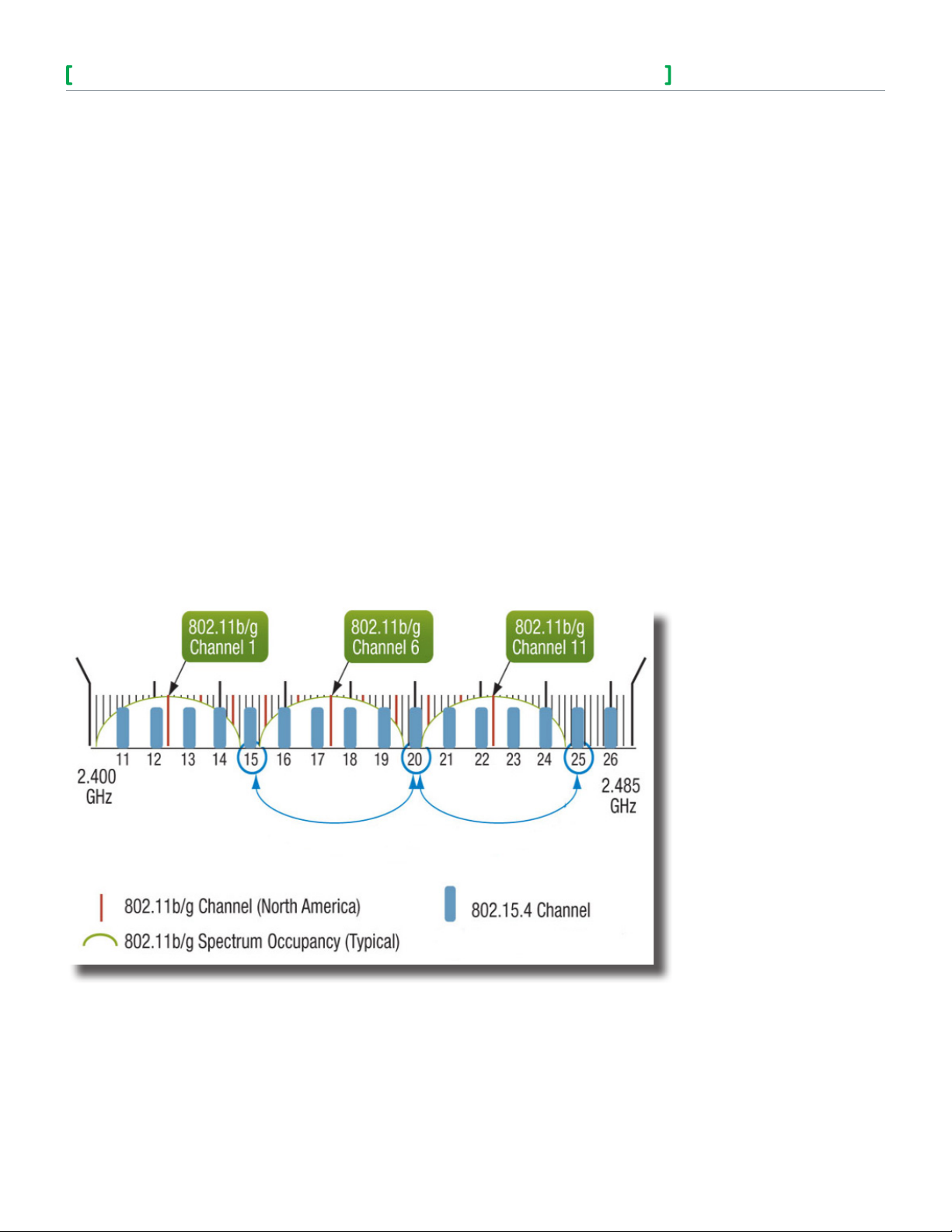
To properly avoid network interference with standard 802.11 WiFi devices in the 2.4GHz spectrum range, it is recommended to
use 802.15.4 channels 15, 20, and 25 only. The 802.11 WiFi transmissions overlap and may interfere with other channel selections
allowed by 802.15, channels 11 to 24. There should be a clear line of sight distance between 2 nodes, and the maximum distance
between each node (Controller) should be under 100 feet (30m) as shown below.
9
Page 10

SE7000/SE8000 Room Controllers ZigBee Pro Wireless Integration Guide
Schneider Electric | IG-SE7000SE8000ZP-A4.EN.03.2014.v2 March 2014
Working with ZigBee Pro
ZigBee Pro has a number of optimizations designed specifically for larger networks comprised of thousands of devices. The
following shows you how to work effectively with ZigBee Pro
Network Layer
A ZigBee Pro network is a set of wireless 802.15.4 nodes cooperating to form a mesh network over which messages hop, from
node to node, to reach a destination. The ZigBee Pro network layer uses the same addressing as 802.15.4 (8-byte EUI46 MAC
and 2-byte short address). Network and routing layers (above 802.15.4) support higher level addressing, discovery, and routing.
Extended PAN ID (EPID)
A ZigBee Pro network is identified by its Extended PAN ID (EPID), which is an 8-byte value. An EPID should be unique for all
networks within range of each other, across all radio channels. The ZC lets you choose a random PAN ID from its EPID, and the
2-byte PAN ID (not EPID) is used for normal traffic. Nodes ignore messages with the wrong PAN ID.
The PAN ID links specific Room Controllers to specific ZigBee Pro Coordinators. For every Controller reporting to a Coordinator,
you must set the same channel value both on the Coordinator and the Room Controller(s).
Channels
The Channel links specific Room Controllers to specific ZigBee Pro Coordinators. For every Room Controller reporting to a
Coordinator, you must set the same channel value both on the Coordinator and the Room Controller(s).
It is recommended to use Channels 15, 20, and 25. The default value of 10 is not a valid channel, and the valid range of available
channel is from 11 to 25.
10
Router, End Device, Coordinator, Trust Center
When a ZigBee Pro node attempts to join a network, it scans all channels for existing ZigBee Pro networks. Any ZigBee
Coordinator can form a network by choosing a Channel, PAN ID, and EPID, which often is its own MAC address (EUI64). A ZigBee
Coordinator is automatically assigned the short address 0x0000 referred to as the ZigBee Coordinator or ZC.
ZigBee Pro Coordinators and Routers are the nodes that participate in routing messages on the mesh. ZigBee Pro Routers and
are always powered on.
A ZigBee Pro End Device (ZED) does not route messages for other devices. A ZED is usually asleep but can send a message to
the ZigBee Pro network where it then gets routed. A ZED only receives messages by polling its parent as long as the parent is
within one hop (radio range) of the ZED.
A ZigBee Pro Trust Center (TC) stores and distributes security keys in the network. The Trust Center is a powered device in the
network with sufficient resources to provide Trust Center services. Security material can be transmitted out of band (on the wire) to
the Trust Center.
Broadcasting
ZigBee Pro supports broadcasting, but network broadcasts are discouraged for normal operation because a broadcast message
must be propagated to all nodes in the network, which generates a lot of traffic. In addition, all nodes must repeat the message,
and each node must wait until there is a clear channel to transmit. A broadcast is limited by a radius value that decrements for
each hop.
Security and Trust Center
Security is enforced by the Trust Center service, which currently resides on a single node, and has the following two key types:
• Network Key: protects the network from outside access.
• Application Link Key: protects transactions between a pair of nodes and from other nodes in the same network.
Network Key
All messages are encrypted by a Network Key and every node in the network must know the Network Key. The Network Key is a
shared secret, but may change over the life of the network.
At every hop along its route to its destination, the Network Key is used to decrypt the message for processing, and then reencrypt the message before forwarding. A Trust Center decides if a device can join the network and sends the Network Key to
the device attempting to join the network. The Trust Center may have a list of MAC addresses to prevent or allow nodes to join
the network. The Trust Center may also require devices attempting to join the node have a unique Trust Center Link Key the Trust
Center has in a database.
Page 11

SE7000/SE8000 Room Controllers ZigBee Pro Wireless Integration Guide
Schneider Electric | IG-SE7000SE8000ZP-A4.EN.03.2014.v2 March 2014
Application Link Keys
An Application Link Key is used to encrypt only the application payload of the message. The payload is only decrypted at the
destination, and is therefore secure from any other nodes that come across the message along the route. Application Link Keys
are distributed to a pair of nodes by the Trust Center, and each node keeps a table of Application Link Key/node entries.
Trust Center Link Keys
The Trust Center Link Key is an intrinsic Application Link Key stored in every node and always used when a node talks to the
Trust Center. Each device may have a unique Trust Center Link Key, or all Trust Center Link Keys may be the same shared secret
value.
The Trust Center Link Key defines the trust relationship between the node and the Trust Center. If all Trust Center Link Keys are
the same in every node, then every node on the network can decrypt Trust Center messages from each node. Conversely, if all
Trust Center Link Keys are unique, then each node must communicate individually to the Trust Center securely.
The Trust Center Link Key has a default value which provides no security. To secure the network, the Trust Center Link Key must
be changed during a node’s commissioning time. The Trust Center must also be informed so it can communicate with the node
over its lifetime.
A Trust Center Link Key may become vulnerable under the following conditions:
1. A new secret Trust Center Link Key is transported to a new node at commissioning and gets encrypted with the default Trust
Center Link Key.
2. A new node joins the network, is sent to the Network Key, and encrypted with the node‘s Trust Center Link Key.
11
3. The Trust Center decides to roll (change) the Network Key it transports to each node using each node’s Trust Center Link
Key.
Joining a Network
To join a network, the network needs to be ‘open’ (permit join parameter selected). Any router node may open itself, however the
node that wants to join must be in range of an open node. Once a node successfully joins a network, an announcement is sent to
all nodes. The Trust Center authorizes the new node on the network and transports the Network Key to the newly joined node. If
the Trust Center does not authorize the node, the node is not permitted to join the Network. The Network Key is encrypted with
the Trust Center Link Key that the Trust Center stores for all nodes.
Application Layer
All standard messages are sent and received using the cluster identifier.
Endpoint
A ZigBee Pro endpoint is a port or instance of a device type. A node or device is defined by a single ZigBee Pro radio and stack,
and a ZigBee Pro device type is defined as having particular clusters that it supports.
To address an application message, one of the following options are present in the message:
• [short address] [endpoint] [cluster]
• [broadcast address] [endpoint] [cluster] (used for generic clusters)
• [broadcast address] [broadcast endpoint] [cluster]
Endpoints have a device type and a list of clusters that support the function of the device.
ZigBee devices have up to 240 endpoints. Applications may use endpoints numbered 1-240 and there is no correlation between
application and endpoint number. Endpoint 0 is reserved for use by the ZigBee Device Object (ZDO) for network discovery
and binding services. Endpoint 0xFF is the broadcast endpoint. Each endpoint provides one simple descriptor that describes
the device type, application profile identifier, and a list of input and output clusters. A ZigBee Pro application profile is an interoperable domain, such as the ZigBee Pro Building Automation.
Page 12

SE7000/SE8000 Room Controllers ZigBee Pro Wireless Integration Guide
Schneider Electric | IG-SE7000SE8000ZP-A4.EN.03.2014.v2 March 2014
Cluster
An endpoint supports a limited number of clusters. Duplicate clusters on an endpoint are not allowed. Clusters have mandatory and
optional attributes. An attribute is a data value stored on a device and has a particular data type.
Clusters can only communicate to another cluster with the same cluster identifier to form a communication transaction. One
counterpart of the communication is the output cluster (client cluster), and the other counterpart is the input cluster (server cluster).
Usually, the client sends a request and the server responds, however the server can also send unsolicited alarms, reports, etc. Clusters
communicate with commands that are either specific to the cluster or work globally across all clusters. Commands to read, write, and
report cluster attributes (data) are global commands. The support of cluster attributes and commands may be mandatory or optional.
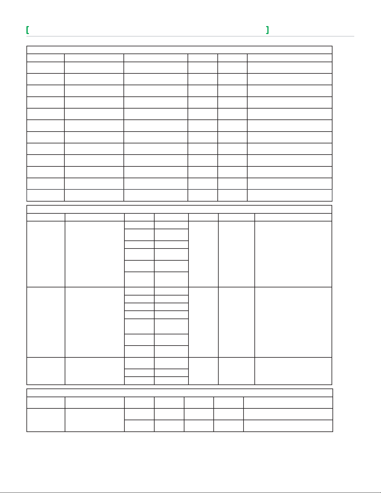
Supported Cluster
12
PartNumber Basic Identify Groups Scenes Thermostat
SE7657B X X X X X X X X X X
SE7656B X X X X X X X X X
SE7652A X X X X X X X X X
SE7652H X X X X X X X X X
SE7652B X X X X X X X X X
SE7605B X X X X X X X X X
SE7600B X X X X X X X X X
SE7600A X X X X X X X X X
SE7600H X X X X X X X X X
SE7607B X X X X X X X X X X
SE7350C X X X X X X X X X X
SE7300C X X X X X X X X X
SE7355C X X X X X X X X X X
SE7305C X X X X X X X X X
SE7350F X X X X X X X X X X
SE7300F X X X X X X X X X
SE7355F X X X X X X X X X X
SE7305F X X X X X X X X X
SE7200C X X X X X X X X
SE7200F X X X X X X X X
SE7300A X X X X X X X X X
SE7305A X X X X X X X X X
SE7350A X X X X X X X X X X
SE7355A X X X X X X X X X X
SE7600F X X X X X X X X X
SE7652F X X X X X X X X X
SE7606E X X X X X X X X X
SE7656E X X X X X X X X X
SE7600W X X X X X X X X X X
SE7652W X X X X X X X X X X
Temperature
Measurement
Thermostat
UI
Conguration
Occupancy
Sensing
FanControl
Measurement
Note: The end point number for all devices is 10
Relative
Humidity
Attributes Supported in Specified Clusters for Thermostat Clusters
THERMOSTATCLUSTER
AttributeID AttributeName Range Access Default Function
0x0000 LocalTemperature
0x0001 OutdoorTemperature
0x0002 Occupancy
0X0003 AbsMinHeatSetpointLimit
Temperature, min=40°F(-40°C),
max=122°F(50°C)
Temperature, min=40°F(-40°C),
max=122°F(50°C)
True = Occupied,
False=Unoccupied
Temperature, min=40°F(4.5°C),
max=90°F(32°C)
Read Only -
Read Only -
Read Only Unoccupied
Read Only 40°F(4.5°C)
Displays the Room temperature in degrees
Celsius and is measured locally or over the
network.
Displays the OA temperature in degrees
Celsius and is measured locally or over the
network.
Displays the occupancy state of the space
and is measure locally or over the network.
States the minimum heating setpoint
permitted.
Page 13
SE7000/SE8000 Room Controllers ZigBee Pro Wireless Integration Guide
Schneider Electric | IG-SE7000SE8000ZP-A4.EN.03.2014.v2 March 2014
THERMOSTATCLUSTER
AttributeID AttributeName Range Access Default Function
0x0004 AbsMaxHeatSetpointLimit
0x0005 AbsMinCoolSetpointLimit
0X006 AbsMaxCoolSetpointLimit
0x0007 PICoolingDemand Percentage, min=0%, max=100% Read Only -
0x0008 PIHeatingDemand Percentage, min=0%, max=100% Read Only -
0x0012 OccupiedHeatingSetpoint
0x0011 OccupiedCoolingSetpoint
0x0013 UnoccupiedCoolingSetpoint
0x0014 UnoccupiedHeatingSetpoint
0x0016 MaxHeatSetpointLimit
0x0017 MinCoolSetpointLimit
0x0019 MinSetpointDeadBand
Temperature, min=40°F(4.5°C),
max=90°F(32°C)
Temperature, min=54°F,
max=100°F
Temperature, min=54°F(12°C),
max=100°F(37.5°C)
Temperature, min=40°F(4.5°C),
max=90°F(32°C)
Temperature, min=54F(12C),
max=100F(37.5C)
Temperature, min=54°F(12°C),
max=100°F(37.5°C)
Temperature, min=40°F(4.5°C),
max=90°F(32°C)
Temperature, min=40°F(4.5°C),
max=90°F(32°C)
Temperature, min=54°F(12°C),
max=100°F(37.5°C)
Temperature, min=2°F(1°C),
max=5°F(2.5°C)
Read Only 86°F(30.0°C)
Read Only 61°F(16.0°C)
Read Only 100°F(37.5°C) States the maximum cooling setpoint.
Read Only 72°F(22°C)
Read/Write 74°F(23°C)
Read/Write 80°F(27°C)
Read/Write 62°F(17°C)
Read/Write 90°F(32°C)
Read/Write 54°F(12°C)
Read/Write 2°F(1°C)
States the maximum heating setpoint
permitted.
States the minimum cooling setpoint
permitted.
Specifies the level of cooling demanded by
the PI control loop in %.
Specifies the level of heating demanded by
the PI control loop in %.
Specifies the heating mode setpoint when the
room is occupied.
Specifies the cooling mode setpoint when the
room is occupied.
Specifies the cooling mode setpoint when the
room is unoccupied.
Specifies the heating mode setpoint when the
room is unoccupied.
Specifies the maximum heating setpoint
permissible.
Specifies the minimum cooling setpoint
permissible.
Specifies the minimum difference between
heat and cool setpoints.
13
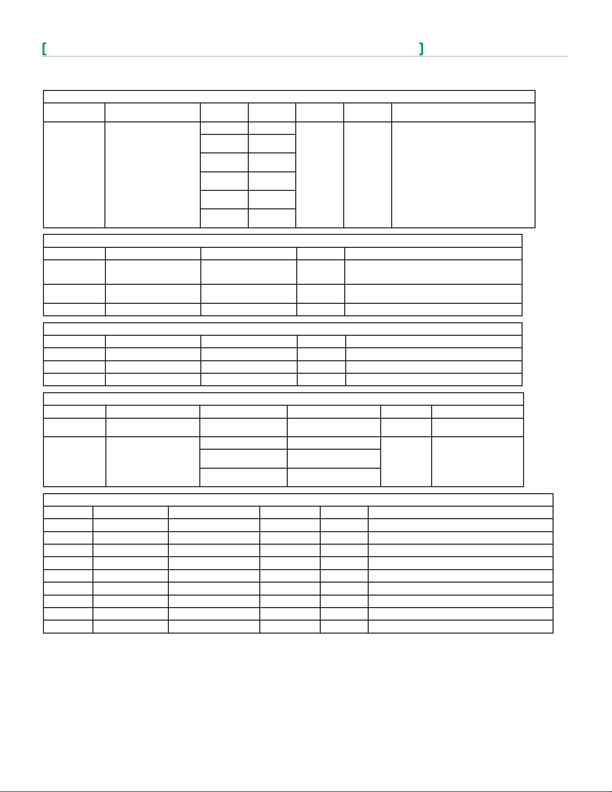
THERMOSTAT CLUSTER
Attribute ID Attribute Name Range Text Description Access Default Function
0x00 Cooling Only
Cooling with
Reheat
Heating with
Reheat
Cooling and
Heating 4 pipe
Cooling and
Heating 4 pipe
with Reheat
Emergency
heating – NOT
USED
Precooling- NOT
USED
Fan Only – NOT
USED
Local
Occupancy
Read/Write
Read/Write Cool Specifies the current operating mode.
Read/Write Local Occupancy Specifies the occupancy mode.
Cooling and
Heating 4 pipe
Specifies the overall operating
environment.
0x001b ControlSequenceOfOperation
0x001c SystemMode
0x0650 Occupancy Command
0x01
0x02 Heating Only
0x03
0x04
0x05
0x00 Off
0x01 Auto
0x02 Cool
0x03 Heat
0x04
0x05
0x06
0x00
0x01 Occupied
0x02 Unoccupied
THERMOSTAT UI CONFIGURATION CLUSTER
Attribute ID Attribute Name Range
0x00
0x0000 TemperatureDisplayMode
0x01
Text
Description
Temperature
in Celsius
Temperature
in Fahrenheit
Access Default Function
Read/Write Celsius Specifies the units of the temperature displayed
Page 14
SE7000/SE8000 Room Controllers ZigBee Pro Wireless Integration Guide
Schneider Electric | IG-SE7000SE8000ZP-A4.EN.03.2014.v2 March 2014
THERMOSTAT UI CONFIGURATION CLUSTER
Attribute ID Attribute Name Range
0x00 No lockout
0x01
0x02
0x0001 KeypadLockout
Attribute ID Attribute Name Range Access Function
0x0000 Measured Value
0x0001 MinMeasuredValue
0x0002 MaxMeasuredValue Temperature, max=122°F(50°C) Read Only Indicates the maximum value capable of being measured.
Attribute ID Attribute Name Range Access Function
0x0000 Measured Value Humidity, min=0%, max=100% Read Only Represents the relative humidity in %.
0x0001 MinMeasuredValue Temperature, min=0% Read Only Indicates the minimum value capable of being measured.
0x0002 MaxMeasuredValue Temperature, max=100% Read Only Indicates the maximum value capable of being measured.
0x03
0x04
0x05
TEMPERATURE MEASUREMENT CLUSTER
Temperature,
min=40°F(-40°C),
max=122°F(50°C)
Temperature,
min=40°F(-40°C)
RELATIVE HUMIDITY MEASUREMENT CLUSTER
Text
Description
Level 1
lockout
Level 2
lockout
Level 3
lockout
Level 4
lockout
Level 5
lockout
Access Default Function
Read/Write No lockout
Read Only Represents the temperature in Celsius.
Read Only Indicates the minimum value capable of being measured.
Specifies level of functionality that is available
to the user via the keypad.
14
OCCUPANCY SENSING CLUSTER
Attribute ID Attribute Name Range / Index Text Description Access Function
0x0000 Occupancy Occupied or Unoccupied - Read Only
0x00 PIR
0x0001 OccupancySensor Type
Attribute ID Attribute Name Range Access Default Function
0x0000 ZCL Version - Read Only 1 Specifies the version number of the ZigBee Cluster Library.
0x0001 Application Version - Read Only 1 Specifies the version number of the application software.
0x0002 Stack Version - Read Only 0x30 Specifies the version number of the ZigBee Stack.
0x0003 HWVersion - Read Only 0 Specifies the version number of the hardware.
0x0004 ManufacturerName - Read Only Viconics Specifies the manufacturer name.
0x0005 ModelIdentifier - Read Only - Specifies the model number.
0x0007 PowerSource - Read Only - Specifies the sources of power available to the device.
0x0010 LocationDescription - Read/Write - Describes the physical location of the device.
0x0012 DeviceEnabled 0x00=Disabled,0x01=Enabled Read/Write Enabled Specifies if the device is enabled or disabled.
0x01
0x02
BASIC CLUSTER
Ultrasonic
NOT USED
PIR and ultrasonic
NOT USED
Read Only
Specifies in the occupancy
sensed.
Specifies the type of
occupancy sensor.
Page 15

SE7000/SE8000 Room Controllers ZigBee Pro Wireless Integration Guide
Schneider Electric | IG-SE7000SE8000ZP-A4.EN.03.2014.v2 March 2014
FAN CONTROL CLUSTER
Attribute
ID
0x0000 FanMode
0x0001 FanModeSequence
Attribute ID Attribute Name Access Default Function
0x0000 Identify Time Read/Write 0x0000 Specifies the time in seconds that the device will continue to indentify itself.
Attribute Name
Range /
Index
0x00 Off
0x01 Low
0x02 Medium
0x03 High
0x04 On
0x05 Auto
0x06 Smart
0x00 Low/Med/High
0x01 Low/High
0x02 Low/Med/High/Auto
0x03 Low/ High/Auto
0x04 On/Auto
Text Description Access Default Function
IDENTIFY CLUSTER
Read/Write Auto Specifies the current speed of the fan.
Read/Write Low/Med/High/Auto Specifies the possible fan speeds available.
15
GROUPS CLUSTER
Attribute ID Attribute Name Range Access Function
0x0000 NameSupport
Attribute ID Attribute Name Access Function
0x0000 SceneCount Read Only Specifies the number of scenes currently in the devices scene table.
0x0001 CurrentScene Read Only Holds the Scene ID of the scene last invoked.
0x0002 CurrentGroup Read Only Holds the Group ID of the scene last invoked.
0x0003 SceneValid Read Only
0x0004 NameSupport Read Only
0=Not Supported
1=Supported
Read Only Indicates if group names are supported.
SCENES CLUSTER
Indicates whether the state of the device corresponds to that associated with CurrentScene
and CurrentGroup attributes. True indicates they are valid, false indicates not valid.
Indicates if scene names are supported. Value of 1 indicates they are supported, 0 indicates
not supported.
Attributes
Attributes are data values referenced by a 2-byte identifier. Cluster commands can access attributes. The Read Attribute and
Write Attribute commands use a list of attribute identifiers that must exist under the same cluster. Because each wireless message
targets a single endpoint and single cluster, it is not possible to address multiple attributes of different clusters on the same or
different endpoints.
Reporting
Reporting is a publish/subscribe service that can be supported by any cluster with any attribute. Reporting pushes attributes
to a data sink, without having the sink device(s) poll for the data. Polling can add latencies in any network, especially a wireless
network. The report service uses global cluster commands that allows a configuring device to create a subscription to data on the
reporting device that sends the data to a sink device.
Reporting parameters can be thresholds and intervals. Any device can read the report parameters from the reporting device,
including the destination(s) of the reports. Reporting can send many attributes, but from only one cluster in a single message.
Page 16

SE7000/SE8000 Room Controllers ZigBee Pro Wireless Integration Guide
Schneider Electric | IG-SE7000SE8000ZP-A4.EN.03.2014.v2 March 2014
Applications in ZigBee Pro
Architecture relies on the correct management of symmetric keys and the correct implementation of methods and
security policies. The architecture of an application may be decided before or after the project is started.
Sensors and Aggregator
Architecture must be considered in cases where several sensors push data to a single or a few aggregators. To operate,
there must be a powered ZigBee Pro infrastructure of ZigBee Pro Routers so sensors, which are sleeping end devices,
have a network to join. This infrastructure can consist of repeaters only, but could also be partially or completely
comprised of common powered actuators such as lights, pumps, valves, and thermostats.
The aggregators are usually part of an overall management system that may or may not do actual control. Control may
be local and the system only sets parameters the local controllers use.
Sensor and Actuator
Robust control is local when the actuator and sensor are close together. In this architecture, the sensor pushes data to
the actuator. The actuator may mirror the data for the system aggregators and send it on behalf of the sensors.
Aggregators may gather data from other networks in the system, process the data, and push it out to the actuators for
local control parameters.
Client and Server
This architecture defines the roles of a conversation between two devices. Both devices may always play the same role
or different roles depending on the service or transaction.
16
Gateway and Proxy
Gateway architecture is used when ZigBee Pro networks are added to existing wired systems that are orders of
magnitude faster than a wireless mesh. A gateway proxies ZigBee Pro data. If it had to read the data from the ZigBee
network each time the system requested it, this would delay the higher speed system. Therefore, data is stored in a
proxy format that is easy to translate to the wired system. The wired system sees the data as being hosted by the
gateway, and the gateway handles the asynchronous updates from the ZigBee Pro network.
Page 17

SE7000/SE8000 Room Controllers ZigBee Pro Wireless Integration Guide
Schneider Electric | IG-SE7000SE8000ZP-A4.EN.03.2014.v2 March 2014
ZigBee Network Diagrams
The ZigBee Pro network is a collection of ZigBee Pro routers (ZR) that create a mesh. The mesh allows messages to hop from
router to router to a destination. The ZigBee Pro coordinator (ZC) is also a router and provides the security Trust Center which
allows, or disallows, nodes to join the network. ZigBee Pro end devices (ZED) are powered sleeping sensors that wake up
periodically to sense and send data. A ZED only receives messages from a routing parent when it wakes up, but does not route
messages.
ZigBee Pro Network
17
ZigBee Pro Message Flow
A request/response transaction may take many hops through the network, but is transparent to the application layer. Sleeping
devices can add long latencies depending on sleep parameters, however there is no guarantee of an immediate response from a
sleeping device.
Page 18

SE7000/SE8000 Room Controllers ZigBee Pro Wireless Integration Guide
Schneider Electric | IG-SE7000SE8000ZP-A4.EN.03.2014.v2 March 2014
18
Deployment
Facilitating proper development and deployment of ZigBee Pro ensures active device support. It also allows for interaction with
other devices sharing the same ZigBee pro network, as well as to actively poll devices to gain information not unavailable through
passive sniffing, and send/receive ZigBee Pro standard and proprietary messages. The following shows various scenarios to assist
you in deploying your ZigBee Pro installation.
Ensure the minimum distance between any node and any WiFi devices (routers, adapters, laps-tops) is at least 3ft (1m). The
preferable distance is 10ft (3m) or more.
The following should be observed when setting-up your device in a ZigBee Pro wireless environment:
• Ensure at least one controller is within 30 ft of the MPM Coordinator for every cluster of 10 Wireless Room Controllers installed.
• Always try to position, if possible, the MPM near the center of all associated wireless controllers.
• Always try to position the MPM near to and in line of sight to as many wireless controllers as possible.
• Try to avoid metal, brick walls, or concrete obstructions between wireless devices.
• Ensure the antenna on the MPM is always perpendicular to the floor.
• Avoid placing controllers near metal or enclosed in metal boxes. If the MPM needs to be installed inside a metal cabinet, use the remote antenna
accessory.
Non line of sight distance for typical gypsum wall partitions made with metal stud frame should be under 30ft (10m).
Deployment Scenarios
Schneider Electric has identified 10 scenarios for setting up a ZigBee Pro wireless environment.
Scenario 1 - 10
NOTE: At the time of writing, this information is not available
Page 19

SE7000/SE8000 Room Controllers ZigBee Pro Wireless Integration Guide
Schneider Electric | IG-SE7000SE8000ZP-A4.EN.03.2014.v2 March 2014
19
Integrate ZigBee Pro with Room Controller and Manager
Integrating a Room Controller with a Manager involves several steps, all of which must be followed to ensure correct integration
between the two devices. Manual setting of the Room Controller is required before you can integrate it with a Manager. Once the
Room Controller is correctly configured, Building Expert allows you to integrate it with a MPM.
Online/Offline Configuration
Device data points for the integrated Device can be set either Online or Offline. Online or Offline configuration is determined by the
Integrator but can involve User preference, installation environment, availability of equipment, or security issues.
Online Room Controller Database Creation with Live Integration Binding Onsite
Online Configuration lets the Integrator install, integrate, and configure every Room Controller with a Manager in real time. Building
Expert lets you set all device data points and save the data to your Manager for immediate use. Online configuration requires you bind
the Room Controller to a Manager at the time of integration. The Bind process instructs the Manager to locate all Devices and record
their COM address and IEEE Mac Address immediately during the binding process. Once this is done, the integration is complete and
any data point or COV polled to the Manager gets saved and takes immediate affect between the Room Controller and the Manager.
Offline Room Controller Database Creation with Onsite Room Controller Integration Binding
Offline configuration follows the exact same principles as Online configuration. The major difference is there is no binding between
the Room Controller and the Manager database as the integration is not done at the customer site. Assigning Object values and
COV status in Offline Configuration is the same as for Online Configuration. Once the Analog or Binary values are assigned to the
data points, all data can be saved directly to the Managers database. However, since the Room Controller and Manager are not
yet integrated, no wireless communication exists between the two Devices. Although the data is stored in the Managers database,
no action is taken as the Manager does not poll the Room Controller nor receive any broadcasts from the Room Controller until
binding between the Room Controller and the Manager is complete. Once you bind the Room Controller and the Manager,
wireless operation exists between the two Devices.
Offline Configuration is typically used in large scale deployment jobs where creating databases, GUIs, alarms, trend logs, etc,
involves a large investment of time.
Room Controller or Manager Replacement in Field
A Room Controller or a Manager can be replaced in the field at any time. Field replacement involves replacing a defective device
with a new device. The new device must be identical in model number and must be configured identically to the defective device
for the replacement to be successful.
If replacing a Room Controller in the field, the new device must have the identical COM address, PAN ID, and Channel as the defective
device to be recognized by the Manager. The new Room Controller can be configured Offline and switched out directly in the field with
the defective device. As soon as the Manager polls the Room Controller or receives a broadcast from the Room Controller after binding,
it recognizes the parameters in the replaced device and treats it with identical behavior as for the defective device.
While a Room Controller is getting replaced, the Manager continues to poll for the device at its regular 30 second intervals unless
the Room Controller is set as the broadcaster.
Room Controller Configuration
You must first configure the Room Controller before you can set-up the ZigBee Pro wireless environment and integrate the device
with a MPM. The Room Controllers require 24 VAC and the MPM can be powered by either 24VAC or 24VDC. The power supply
must be VAC if you want to share power source between the Manager and Room Controller.
The COM address parameter for a Room Controller is required for communication purposes in a SmartStruxure™ Lite network.
The COM address of each Room Controller must be set to a unique number. This ensures the easiest and fastest way to identify a
specific room controller deployed at the site.
The COM address can be any value between 0 - 254, with the default value set as 254.
Room Controllers join ZigBee Pro networks as routers. You must set two communication parameters,
PAN ID and Channel, to enable communication between the Room Controller and the Manager. The
PAN ID and Channel settings must be the same values for all Room Controllers in the same network.
These settings must also be identical to the PAN ID and Channel settings in Building Expert. Any Room
Controller with a PAN ID or Channel setting different than the settings in Building Expert will not get
discovered on the network when you attempt to discover and bind the Device.
A valid PAN ID can be any value between 1 - 1000, with the default value being 0. The Channel setting
can be any Channel between 10 - 25
Page 20

SE7000/SE8000 Room Controllers ZigBee Pro Wireless Integration Guide
Schneider Electric | IG-SE7000SE8000ZP-A4.EN.03.2014.v2 March 2014
Integration
Once you have configured your Room Controller, you must login to Building Expert to integrate the Room Controller with the
Manager. To integrate any Room Controller with a Manager, the Manager must know the Device exists. Building Expert allows you
to add any SE7000 or SE8000 series Room Controller to your solution. Once the device is added, you can use Building Expert
to integrate it with the Manager. It is essential you add the correct Room Controller model when adding a Device to your solution.
Building Expert does not allow you to integrate an incorrect model with your Manager.
You can add more than one Device to your solution, including different model types, before integrating them with your Manager.
However, it is recommended to not add more than 20 Room Controllers per Manager each with 20 data points. This is due to
the available number of data points which should not exceed more than 400. For example, 20 Room Controllers each with 20
data points, or 10 Room Controllers each with 40 data points, falls in the accepted range per Manager. As well, on a ZigBee Pro
network, a maximum of 25 nodes (1 monitor and 24 routers) is the recommended maximum.
The Manager and Room Controllers are not end devices. The Manager can be configured as either a coordinator or router on a
ZigBee Pro network. The Room Controllers are usually configured as routers except when they are used in a network without any
Manager. In this condition, the Room Controller must be configured as the coordinator.
20
Integration with Manager using Building Expert
When all Devices are added to project, Building Expert lets you integrate them with the Manager. You can only integrate one Room
Controller at a time with your Manager. You must individually select the Room Controller you want to integrate from the list of
available Devices.
Binding
After selecting the Device, you must use Building Expert to Bind the Device with the Manager. Binding involves the Manager using
a wireless protocol to search for the COM address and Extended Node ID to integrate itself with the Device. Once the Manager
locates the two parameters, the Binding process completes the integration of the Room Controller and the Manger.
Page 21

SE7000/SE8000 Room Controllers ZigBee Pro Wireless Integration Guide
Schneider Electric | IG-SE7000SE8000ZP-A4.EN.03.2014.v2 March 2014
Setting Device Data Points
After integrating the Room Controller with the Manager, you must set the Device data points in Building Expert. There are two
types of Device data points you can set; Required for Block Programming and Others. You must set the Required for Block
Programming with the Device data points.
Setting Device data points involves assigning an
Analog Value or Binary to from the drop-down menu.
Once all the required Device data points for all Room
Controllers are set, you can set as many of the
Other Device data points as you want, provided the
combined total of all Device data points for all Room
Controllers does not exceed 400 data points per
Manager.
You can not assign the same Analog Value to more
than one Object, and Analog Values should be set
sequentially in your project.
All Objects with an assigned Device data point show in Building Expert. You can modify the value for any data points by clicking
on it and making the desired modification directly in Building Expert.
21
Page 22

SE7000/SE8000 Room Controllers ZigBee Pro Wireless Integration Guide
Schneider Electric | IG-SE7000SE8000ZP-A4.EN.03.2014.v2 March 2014
Change of Values
value changed, the Manager receives the COV(s) and reads the result based on preset conditions to determine the Present Value
of the Room Controller. If any action is necessary based on the COV, the Manager sends instructions to the necessary device.
Selecting the COV toggle box allows the Manager to subscribe to a specific data point and receive any change in data
instantaneously, rather then waiting for the next 30 second poll interval. When COV is toggled, the Room Controller becomes the
broadcaster and sends any change of data point indicating a change in the Present Value immediately to the Manager. For
example, if the Occupancy of a room changes, the Room Controller automatically broadcasts the data point to the Manager
letting it know immediately the state of the room occupancy. By enabling a COV for a data point, the regular 30 second polling of
that data point/object is no longer in effect, and therefore, the Manager relies on the Room Controller to inform the it of any COV
and report its Present Value.
The Room Controller continues to send any COV to
the Manager at the time the COV occurs as long as
the COV stays toggled. If the data point is toggled
off, any immediate COV is not broadcasted to the
Manager. In this condition, the Manager will only
learn of any present value changes at the next 30
second poll interval.
Note: A single Manager can only subscribe to a
maximum COV of 20 Objects per Room Controller.
22
Page 23

SE7000/SE8000 Room Controllers ZigBee Pro Wireless Integration Guide
Schneider Electric | IG-SE7000SE8000ZP-A4.EN.03.2014.v2 March 2014
Procedures - Integrate Room Controller and Manager
The following procedures show how to integrate a SE7000/SE8000 series Room Controller with a Multi-purpose Manager in a
ZigBee Wireless Pro environment.
Procedure - Configure SE7200, SE7300, SE7600 and SER7300 Series
1. Press and hold MENU/OVERRIDE for 8 seconds until PswrdSet shows.
2. Using up or down arrow, set Password to any value between 0 - 1000.
3. Push YES/OVERRIDE when you set Password.
4. PressNO/OVERRIDE until PANID shows.
23
5. Using up or down arrow, set PANID to any value between 0 - 500.
6. Push YES/OVERRIDE when you set PAN ID. Record value for later use.
7. Push YES/OVERRIDE until Channel shows.
8. Using up or down arrow, set Channel to any value between 11 - 25.
9. Push YES/OVERRIDE when you set Channel. Record value for later use.
Procedure - Configure SE8000 Series
1. On right side of date, touch and hold this point for 3 seconds to enter setup mode.
2. Push Network button.
Page 24

SE7000/SE8000 Room Controllers ZigBee Pro Wireless Integration Guide
Schneider Electric | IG-SE7000SE8000ZP-A4.EN.03.2014.v2 March 2014
3. Set unique COMaddress.
4. Using up/down arrows, enter COM address value.
5. Set ZigBeePan.ID.
6. Using up/down arrows, enter ZigBee pan. ID value.
7. Set ZigBeechannel.
8. Using up/down arrows, enter Channel number.
9. Push BacktoSetuppage.
24
Procedure - Login to Manager
IconSmartStruxureWare™BuildingExpertrequiresFirefoxversionESR.
http://www.mozilla.org/en-US/firefox/organizations/all.html.
1. Type default address in address bar.
• 10.50.80.3for MPM-GW and MPM-UN,
• 10.50.80.4 for MPM-VA.
Building Expert login page shows.
IMPORTANT
Youcandownloaditat
2. Select Language (default English).
3. Enter User name (default ‘admin’).
4. Enter Password (default ‘admin’).
5. Push Login button. Building Expert loads to
default page.
Page 25

SE7000/SE8000 Room Controllers ZigBee Pro Wireless Integration Guide
Schneider Electric | IG-SE7000SE8000ZP-A4.EN.03.2014.v2 March 2014
Procedure - Configure Manager
1. In Building Expert, click Configuration tab.
2. In Controller Settings (CFG1), set Adjust Time, Save Period, Time Zone Offset, and Enable DST (if applicable).
25
3. In ZigBee field of Network Settings (C2G1), set Manager to be Passive or Monitor.
4. Toggle Enable.
5. In Ethernet Settings (ETH1) field, set IP, Netmask, Gateway, DNS, and Email Source.
6. In ZigBee Settings (ZBC1) field, set Node Type as Coordinator or Router.
7. Set Channel to value between 11 - 25.
8. Set Stack Profile to 2 - ZigBee_Pro.
9. Click Save button.
Page 26

SE7000/SE8000 Room Controllers ZigBee Pro Wireless Integration Guide
Schneider Electric | IG-SE7000SE8000ZP-A4.EN.03.2014.v2 March 2014
Procedure - Add Device
1. In Explorer tab, click Add Device button. A new window opens.
26
2. Select Device you want to add.
3. Click AddDevices button. Building Expert automatically adds Device to your project.
Procedure - Bind and Configure ZigBee Pro Online for 7000 Series
1. In Devices pane, select newly added Device.
2. Navigate down page to ZigBee Room Controller Configuration of Explorer tab.
Page 27

SE7000/SE8000 Room Controllers ZigBee Pro Wireless Integration Guide
Schneider Electric | IG-SE7000SE8000ZP-A4.EN.03.2014.v2 March 2014
3. Select Bind tab A new window opens and Building Expert searches for the Com Address and Extended Node ID for your
device.
27
4. From Select device window, select Device you want to bind with Controller.
5. Push Bind device button. Building Expert adds Device Extended Node ID and COM Address to your project.
Page 28

SE7000/SE8000 Room Controllers ZigBee Pro Wireless Integration Guide
Schneider Electric | IG-SE7000SE8000ZP-A4.EN.03.2014.v2 March 2014
Procedure - Assign Device Data Points
1. In Controller object, click Unassigned for device data point to open drop-down menu.
2. Assign an Analog or Binary value to data point.
3. In COV field, toggle any data point you want to have poll Manager whenever device has change in present value.
4. Repeat steps 1 - 3 for remaining data points to a maximum of 20 COVs.
28
Page 29

SE7000/SE8000 Room Controllers ZigBee Pro Wireless Integration Guide
Schneider Electric | IG-SE7000SE8000ZP-A4.EN.03.2014.v2 March 2014
Procedure - Configure ZigBee Pro Offline for SE7000 Series
1. Assign Device Data Points to Manager. Refer to Procedure - Assign Device Data Points.
2. Bind Room Controller and Manager. Refer to Procedure - Bind and Configure ZigBee Pro Online for 7000 Series.
Configure ZigBee Pro Online for SE8000 Series
1. Assign Device Data Points to Manager. Refer to Procedure - Assign Device Data Points.
2. Bind Room Controller and Manager. Refer to Procedure - Bind and Configure ZigBee Pro Online for 7000 Series.
Procedure - Configure Points and Change of Values for 8300 Series
Refer to Procedure - Assign Device Data Points for SE7000 Series.
Procedure - Configure ZigBee Pro Offline for 8300 Series
Refer to Procedure - Configure Manager for the SE7000 Series
29
Page 30

SE7000/SE8000 Room Controllers ZigBee Pro Wireless Integration Guide
Schneider Electric | IG-SE7000SE8000ZP-A4.EN.03.2014.v2 March 2014
Object Tables
Objects Supported By Models SE7200 and SE7300 Series
Objects Supported By Models SE7200 and SE7300 Series
Object Name
SE7350F5x45P
SE7200C5x45P
Room Temperature √ √ √ √ √ √ √ √ √ √ √ √
Outdoor Temperature √ √ √ √ √ √ √ √ √ √ √ √
Room Humidity √ √
Supply Temperature √ √ √ √ √ √ √ √ √ √ √ √
Occupied Cooling Setpoint √ √ √ √ √ √ √ √ √ √ √ √
Occupied Heating Setpoint √ √ √ √ √ √ √ √ √ √ √ √
Stand-By Cooling Setpoint √ √ √ √ √ √ √ √ √ √ √ √
Stand-By Heating Setpoint √ √ √ √ √ √ √ √ √ √ √ √
Unoccupied Cooling Setpoint √ √ √ √ √ √ √ √ √ √ √ √
Unoccupied Heating Setpoint √ √ √ √ √ √ √ √ √ √ √ √
Dehumidification RH Setpoint √ √
Occupancy Command √ √ √ √ √ √ √ √ √ √ √ √
Sequence of Operation √ √ √ √ √ √ √ √ √ √ √ √
System Mode √ √ √ √ √ √ √ √ √ √ √ √
Fan Mode √ √ √ √ √ √ √ √ √ √
Keypad Lockout √ √ √ √ √ √ √ √ √ √ √ √
Dehumidification Lockout √ √ √ √
Aux Command √ √ √ √ √ √ √ √ √ √ √ √
Password √ √ √ √ √ √ √ √ √ √ √ √
PI Heating Demand √ √ √ √ √ √ √ √ √ √ √ √
PI Cooling Demand √ √ √ √ √ √ √ √ √ √ √ √
Effective Occupancy √ √ √ √ √ √ √ √ √ √ √ √
Dehumidification Status √ √
Fan Status √ √ √ √ √ √ √ √ √ √
Aux Status √ √ √ √ √ √ √ √ √ √ √ √
BI1 Status √ √ √ √ √ √ √ √ √ √ √ √
BI2 Status √ √ √ √ √ √ √ √ √ √ √ √
UI3 Status √ √ √ √ √ √ √ √ √ √ √ √
PIR Motion Status √ √ √ √ √ √ √ √ √ √ √ √
Service Alarm √ √ √ √ √ √ √ √ √ √ √ √
Filter Alarm √ √ √ √ √ √ √ √ √ √ √ √
Window Alarm √ √ √ √ √ √ √ √ √ √ √ √
Temporary Occupancy Time √ √ √ √ √ √ √ √ √ √ √ √
Get From √ √ √ √ √ √ √ √ √ √ √ √
Deadband √ √ √ √ √ √ √ √ √ √ √ √
Heating Setpoint Limit √ √ √ √ √ √ √ √ √ √ √ √
Cooling Setpoint Limit √ √ √ √ √ √ √ √ √ √ √ √
Display Scale √ √ √ √ √ √ √ √ √ √ √ √
Menu Scroll √ √ √ √ √ √ √ √ √ √ √ √
Room Temperature Override √ √ √ √ √ √ √ √ √ √ √ √
Configuration Setpoint Type √ √ √ √ √ √ √ √ √ √ √ √
Outdoor Temperature Override √ √ √ √ √ √ √ √ √ √ √ √
BI1 Configuration √ √ √ √ √ √ √ √ √ √ √ √
BI2 Configuration √ √ √ √ √ √ √ √ √ √ √ √
UI3 Configuration √ √ √ √ √ √ √ √ √ √ √ √
Auto Mode Enable √ √ √ √ √ √ √ √ √ √
Pipe Number √ √ √ √ √ √ √ √ √ √
Output #1 Configuration √ √ √ √
Aux Configuration √ √ √ √ √ √ √ √ √ √ √ √
Fan Mode Sequence √ √ √ √ √ √ √ √ √ √
SE7355F5x45P
VT7300A5x00W
VT7305A5x00W
SE7300F5x45P
SE7305C5x45P
SE7350C5x45P
SE7355C5x45P
SE7305F5x45P
SE7350F5x45P
SE7355F5x45P
30
Page 31

SE7000/SE8000 Room Controllers ZigBee Pro Wireless Integration Guide
Schneider Electric | IG-SE7000SE8000ZP-A4.EN.03.2014.v2 March 2014
Objects Supported By Models SE7200 and SE7300 Series
Object Name
SE7350F5x45P
SE7200C5x45P
Setpoint Function √ √ √ √ √ √ √ √ √ √
Reheat Time Base √ √ √ √ √ √ √ √ √ √ √ √
Proportional Band √ √ √ √ √ √ √ √ √ √ √ √
Auto Fan √ √ √ √ √ √ √ √ √ √
Stand-By Time √ √ √ √ √ √ √ √ √ √ √ √
Unoccupied Time √ √ √ √ √ √ √ √ √ √ √ √
RH Display √ √
Dehumidification Hysteresis √ √
Dehumidification Max Cooling √ √
Control Type √ √ √ √ √
Floating Motor Timing √ √ √ √ √
On Off Control CPH √ √ √ √ √
Direct Reverse Acting √ √ √
SE7355F5x45P
VT7300A5x00W
VT7305A5x00W
SE7300F5x45P
SE7305C5x45P
SE7350C5x45P
SE7355C5x45P
SE7305F5x45P
SE7350F5x45P
SE7355F5x45P
Objects Supported By Models SE7600 Series
Objects Supported By Models SE7600 Series
Object Name
SE7600A5x45P
SE7652A5x45P
SE7600B5x45P
SE7652B5x45P
SE7600F5x45P
SE7652F5x45P
SE7606E5x45P
SE7656E5x45P
SE7605B545P
SE7656B5x45P
SE7607B5x45P
SE7657B5x45P
SE7600H5x45P
SE7652H5x45P
SE7600W5x45P
SE7652W5x45P
Room Temperature √ √ √ √ √ √ √ √ √ √ √ √ √ √ √ √
Room Temperature Override √ √ √ √ √ √ √ √ √ √ √ √ √ √ √ √
Outdoor Temperature √ √ √ √ √ √ √ √ √ √ √ √ √ √ √ √
Outdoor Temperature
Override
Supply Temperature √ √ √ √ √ √ √ √ √ √ √ √ √ √ √ √
Supply RH √ √
Room Humidity √ √ √ √
Room Humidity Override √ √ √ √ √ √
Occupancy Command √ √ √ √ √ √ √ √ √ √ √ √ √ √ √ √
Effective Occupancy √ √ √ √ √ √ √ √ √ √ √ √ √ √ √ √
Occupied Cooling Setpoint √ √ √ √ √ √ √ √ √ √ √ √ √ √ √ √
Occupied Heating Setpoint √ √ √ √ √ √ √ √ √ √ √ √ √ √ √ √
Unoccupied Cooling
Setpoint
Unoccupied Heating
Setpoint
PI Cooling Demand √ √ √ √ √ √ √ √ √ √ √ √ √ √ √ √
PI Heating Demand √ √ √ √ √ √ √ √ √ √ √ √ √ √ √ √
System Mode RTU √ √ √ √ √ √ √ √ √ √ √ √ √ √ √ √
System Mode HPU √ √
Fan Mode √ √ √ √ √ √ √ √ √ √ √ √ √ √ √ √
Y1 Status √ √ √ √ √ √ √ √ √ √ √ √ √ √ √ √
Y2 Status √ √ √ √ √ √ √ √ √ √ √ √ √ √
W1 Status √ √ √ √ √ √ √ √ √ √ √ √
W2 Status √ √ √ √ √ √ √ √
Frost Alarm √ √ √ √ √ √ √ √ √ √ √ √ √ √ √ √
Set Clock Alarm √ √ √ √ √ √ √ √
Service Alarm √ √ √ √ √ √ √ √ √ √ √ √ √ √
Filter Alarm √ √ √ √ √ √ √ √ √ √ √ √ √ √
Fan Lock Alarm √ √ √ √ √ √ √ √ √ √
Fan Lock Alarm √ √ √ √
DI Status √ √
DI1 Status √ √ √ √ √ √ √ √ √ √ √ √
√ √ √ √ √ √ √ √ √ √ √ √ √ √ √ √
√ √ √ √ √ √ √ √ √ √ √ √ √ √ √ √
√ √ √ √ √ √ √ √ √ √ √ √ √ √ √ √
31
Page 32

SE7000/SE8000 Room Controllers ZigBee Pro Wireless Integration Guide
Schneider Electric | IG-SE7000SE8000ZP-A4.EN.03.2014.v2 March 2014
Objects Supported By Models SE7600 Series
Object Name
SE7600A5x45P
SE7652A5x45P
SE7600B5x45P
SE7652B5x45P
SE7600F5x45P
SE7652F5x45P
SE7606E5x45P
SE7656E5x45P
SE7605B545P
SE7656B5x45P
SE7607B5x45P
SE7657B5x45P
SE7600H5x45P
SE7652H5x45P
SE7600W5x45P
SE7652W5x45P
DI2 Status √ √ √ √ √ √ √ √ √ √ √ √
DI1 Config √ √ √ √ √ √ √ √ √ √ √ √
DI2 Config √ √ √ √ √ √ √ √ √ √ √ √
DI Config √ √
Humidifier Output √ √
Dehumidification Status √ √
Dehumidification Hysteresis √ √
Dehumidification Low OA
Lockout
Dehumidification Lockout
Functions
Heating Setpoint Limit √ √ √ √ √ √ √ √ √ √ √ √ √ √ √ √
Cooling Setpoint Limit √ √ √ √ √ √ √ √ √ √ √ √ √ √ √ √
Economizer Output √ √
G Fan Status √ √ √ √ √ √ √ √ √ √ √ √ √ √ √ √
Reversing Valve Status √ √ √ √
Aux Status √ √ √ √ √ √ √ √ √ √ √ √ √ √
PIR Motion Status √ √
PIR Motion Status √ √ √ √ √ √ √ √ √ √ √ √ √
Dehumidification RH
Setpoint
Humidification RH Setpoint √ √
Effective Humidification RH
Setpoint
Humidification High Limit
Setpoint
Low RH Setpoint √ √
Low Temperature Reset RH
Setpoint
High Temperature Reset RH
Setpoint
Temporary Occupancy Time √ √ √ √ √ √ √ √ √ √ √ √ √ √ √ √
Unoccupied Time √ √ √ √ √ √ √ √ √ √ √ √ √ √ √ √
Thermostat Model Number √ √ √ √ √ √ √ √ √ √ √ √ √ √ √ √
Module Firmware Version
Number
Thermostat Firmware Version
Number
Keypad Lockout √ √ √ √ √ √ √ √ √ √ √ √ √ √ √ √
Password √ √
Password √ √ √ √ √ √ √ √ √ √
Password √ √ √ √
Heating Stages √ √ √ √ √ √
Cooling Stages √ √ √ √ √ √ √ √ √ √
Heating CPH √ √ √ √ √ √ √ √ √ √ √ √
Cooling CPH √ √ √ √ √ √ √ √ √ √ √ √ √ √ √ √
Display Scale √ √ √ √ √ √ √ √ √ √ √ √ √ √ √ √
Menu Scroll √ √ √ √ √ √ √ √ √ √ √ √ √ √ √ √
RH Display √ √
Cooling Lockout
Temperature
Powerup Delay √ √ √ √ √ √ √ √ √ √ √ √ √ √ √ √
Progressive Recovery √ √ √ √ √ √ √ √
Aux Contact √ √ √ √ √ √ √ √ √ √ √ √ √ √
Fan Purge Delay √ √ √ √ √ √ √ √ √ √ √ √ √ √ √ √
Anticycle √ √ √ √ √ √ √ √ √ √ √ √ √ √ √ √
Event Display √ √ √ √ √ √ √ √
Get From √ √
√ √
√ √
√ √
√ √
√ √
√ √
√ √
√ √ √ √ √ √ √ √ √ √ √ √ √ √ √
√ √ √ √ √ √ √ √ √ √ √ √ √ √ √ √
√ √ √ √ √ √ √ √ √ √ √ √ √ √ √ √
32
Page 33

SE7000/SE8000 Room Controllers ZigBee Pro Wireless Integration Guide
Schneider Electric | IG-SE7000SE8000ZP-A4.EN.03.2014.v2 March 2014
Objects Supported By Models SE7600 Series
Object Name
SE7600A5x45P
SE7652A5x45P
SE7600B5x45P
SE7652B5x45P
SE7600F5x45P
SE7652F5x45P
SE7606E5x45P
SE7656E5x45P
SE7605B545P
SE7656B5x45P
SE7607B5x45P
SE7657B5x45P
SE7600H5x45P
SE7652H5x45P
SE7600W5x45P
SE7652W5x45P
Get From √ √ √ √ √ √ √ √ √ √ √ √ √ √
Deadband √ √ √ √ √ √ √ √ √ √ √ √ √ √ √ √
Proportional Band √ √ √ √ √ √ √ √ √ √ √ √ √ √ √ √
Frost Protection √ √ √ √ √ √ √ √ √ √ √ √ √ √ √ √
Fan Control √ √ √ √ √ √ √ √ √ √ √ √ √ √ √ √
Heatpump Stages √ √ √ √
Economizer Changeover
Setpoint
√ √ √ √ √ √
Mechanical Cooling Enable √ √ √ √
Mixed Air Setpoint √ √ √ √
High Balance Point √ √
Low Balance Point √ √
Comfort Mode √ √
Reversing Valve Config √ √ √ √
Compressor Auxiliary
Lockout
Fresh Air Alarm √ √
High CO2 Alarm √ √
Economizer Minimum
Position
TRSS √ √ √ √ √ √ √ √ √ √ √ √ √ √ √ √
RH Display √ √
Dehumidification RH
Setpoint
Dehumidification Hysteresis √ √
Dehumidification Low OA
Lockout
Dehumidification Lockout
Functions
Dehumidification Output
Status
Water Temperature √ √
Economizer Output √ √
AI1 Value √ √
Analog Heat Output Status √ √
Fresh Air Level √ √
Supply Heat Lockout Status √ √
CO2 Level √ √
Discharge Air Alarm √ √
Heating Stages √ √
Fresh Air Max Range √ √
Discharge High Limit
Setpoint
Discharge Low Limit
Setpoint
AI1 Configuration √ √
Minimum Supply Heat
Setpoint
Supply Heat Lockout
Temperature
Supply PI Heat Demand √ √
Minimum Fresh Air √ √
Maximum Fresh Air √ √
Minimum CO2 Level √ √
Maximum CO2 Level √ √
Analog Heat Output Status √ √
Supply Heat Lockout Status √ √
√ √ √ √
√ √
√ √
√ √
√ √
√ √
√ √
√ √
√ √
√ √
√ √
33
Page 34

SE7000/SE8000 Room Controllers ZigBee Pro Wireless Integration Guide
Schneider Electric | IG-SE7000SE8000ZP-A4.EN.03.2014.v2 March 2014
Objects Supported By Models SE7600 Series
Object Name
SE7600A5x45P
SE7652A5x45P
SE7600B5x45P
SE7652B5x45P
SE7600F5x45P
SE7652F5x45P
SE7606E5x45P
SE7656E5x45P
SE7605B545P
SE7656B5x45P
SE7607B5x45P
SE7657B5x45P
SE7600H5x45P
SE7652H5x45P
SE7600W5x45P
SE7652W5x45P
Discharge Air Alarm √ √
Discharge High Limit
Setpoint
Discharge Low Limit
Setpoint
Minimum Supply Heat
Setpoint
Supply Heat Lockout
Temperature
Supply PI Heat Demand √ √
√ √
√ √
√ √
√ √
Objects Supported By Models SE7300 Controllers
Objects Supported By Models SE7300 Controllers
Object Name
SER7300A545P
SER7305A5x45P
SER7350A5x45P
SER7355A5x45P
Auto Mode Enable
Pipe Number
Fan Mode Sequence
Setpoint Function
Proportional Band
Auto Fan
Stand-By Time
Unoccupied Time
RH Display
Dehumidification Hysteresis
Dehumidification Max
Cooling
RUI1 Configuration
RBI2 Configuration
RUI1 Status
RBI2 Status
Sequence of Operation
Heating CPH
Cooling CPH
Heat No/Nc
Cool No/Nc
Pulsed Heat
Low Battery Alarm
Wireless Window Switch
Used
Wireless Window Switch
Status
Wireless Door Switch Used
Wireless Door Switch Status
Heating Demand Limit
Cooling Demand Limit
√ √ √ √
√ √ √ √
√ √ √ √
√ √ √ √
√ √ √ √
√ √ √ √
√ √ √ √
√ √ √ √
√ √
√ √
√ √
√ √ √ √
√ √ √ √
√ √ √ √
√ √ √ √
√ √ √ √
√ √ √ √
√ √ √ √
√ √ √ √
√ √ √ √
√ √ √ √
√ √ √ √
√ √ √ √
√ √ √ √
√ √ √ √
√ √ √ √
√ √ √ √
√ √ √ √
34
Page 35

SE7000/SE8000 Room Controllers ZigBee Pro Wireless Integration Guide
Schneider Electric | IG-SE7000SE8000ZP-A4.EN.03.2014.v2 March 2014
List of Property Numeric Values Range Restrictions
List of Property Numeric Values Range Restrictions
Object Name Object Type Thermostat Range / Indexes
AI1 Value Numeric Point volt,min=0,max=10
Analog Heat Output Status Numeric Point percent,min=0,max=100
AO2 Outside Air Lockout
Setpoint
AO2 Status Numeric Point percent,min=0,max=100
BO5 Outside Air Lockout
Setpoint
ByPass Damper Position Numeric Point percent,min=0,max=100
ByPass Damper Position
Or VFD
CO2 Level Numeric Point
Cooling Demand Limit Numeric Writable percent,min=0,max=100
Cooling Lockout Temperature Numeric Writable temperature,min=-40,max=95
Cooling Setpoint Limit Numeric Writable temperature,min=54,max=100
Damper Max Heat Position Numeric Writable percent,min=0,max=100
Damper Maximum Position Numeric Writable percent,min=0,max=100
Damper Minimum Position Numeric Writable percent,min=0,max=100
Damper Position Numeric Point percent,min=0,max=100
Deadband Numeric Writable temperature,min=2.0,max=4.0
Deadband Numeric Writable temperature,min=2.0,max=5.0
Dehumidification Hysteresis Numeric Writable percent,min=2,max=20
Dehumidification Low OA
Lockout
Dehumidification Max Cooling Numeric Writable percent,min=20,max=100
Dehumidification RH Setpoint Numeric Writable percent,min=15,max=95
Dehumidification RH Setpoint Numeric Writable percent,min=30,max=95
Discharge High Limit Setpoint Numeric Writable temperature,min=70,max=150
Discharge Low Limit Setpoint Numeric Writable temperature,min=35,max=65
Economizer Changeover
Setpoint
Economizer Maximum Position Numeric Writable percent,min=0,max=100
Economizer Minimum Position Numeric Writable percent,min=0,max=100
Economizer Output Numeric Point percent,min=0,max=100
Effective Humidification RH
Setpoint
Fresh Air Level Numeric Point
Fresh Air Max Range Numeric Writable
Get From Numeric Writable none,min=0,max=254
Heating Demand Limit Numeric Writable percent,min=0,max=100
Heating Lockout Temperature Numeric Writable temperature,min=-15,max=120
Heating Setpoint Limit Numeric Writable temperature,min=40,max=90
High Balance Point Numeric Writable temperature,min=34,max=90
High Temperature Reset RH
Setpoint
Humidification High Limit
Setpoint
Humidification RH Setpoint Numeric Writable percent,min=10,max=90
Humidifier Output Numeric Point percent,min=0,max=100
Low Balance Point Numeric Writable temperature,min=-40,max=30
Low RH Setpoint Numeric Writable percent,min=10,max=90
Low Temperature Reset RH
Setpoint
Maximum CO2 Level Numeric Writable
Maximum Fresh Air Numeric Writable
Numeric Writable temperature,min=-40,max=122
Numeric Writable temperature,min=-40,max=122
Numeric Point percent,min=0,max=100
parts per
million,min=0,max=2000
Numeric Writable temperature,min=-40,max=122
Numeric Writable temperature,min=14,max=70
Numeric Point percent,min=0,max=100
cubic feet per
minute,min=0,max=20000
cubic feet per
minute,min=0,max=20000
Numeric Writable temperature,min=20,max=55
Numeric Writable percent,min=50,max=90
Numeric Writable temperature,min=-40,max=15
parts per
million,min=0,max=2000
cubic feet per
minute,min=0,max=20000
35
Page 36

SE7000/SE8000 Room Controllers ZigBee Pro Wireless Integration Guide
Schneider Electric | IG-SE7000SE8000ZP-A4.EN.03.2014.v2 March 2014
List of Property Numeric Values Range Restrictions
Object Name Object Type Thermostat Range / Indexes
36
Minimum CO2 Level Numeric Writable
Minimum Fresh Air Numeric Writable
Minimum Supply Heat Setpoint Numeric Writable temperature,min=50,max=72
Mixed Air Setpoint Numeric Writable temperature,min=50,max=90
Occupied Cooling Setpoint Numeric Writable temperature,min=54,max=100
Occupied Heating Setpoint Numeric Writable temperature,min=40,max=90
Outdoor Temperature Numeric Writable temperature,min=-40,max=122
Outdoor Temperature Numeric Writable temperature,min=-40,max=150
Password Numeric Writable none,min=0,max=1000
PI Cooling Demand Numeric Point percent,min-0,max=100
PI Heating Demand Numeric Point percent,min-0,max=100
Powerup Delay Numeric Writable seconds,min=10,max=120
Return Air Temperature Numeric Point temperature,min=-40,max=122
Room Humidity Numeric Writable percent,min=0,max=100
Room Humidity Numeric Writable percent,min=5,max=90
Room Temperature Numeric Writable temperature,min=-40,max=122
RTC Comm Address Numeric Writable none,min=1,max=127
Standby Cooling Setpoint Numeric Writable temperature,min=54,max=100
Standby Heating Setpoint Numeric Writable temperature,min=40,max=90
Standby Time Numeric Writable hours,min=5.0,max=240.0
Static Pressure Numeric Point pascal,min=0,max=5000
Static Pressure Setpoint Numeric Writable pascal,min=0,max=5000
Supply Heat Lockout
Temperature
Supply PI Heat Demand Numeric Point percent,min=0,max=100
Supply RH Numeric Point percent,min=0,max=100
Supply Temperature Numeric Point temperature,min=-40,max=122
Supply Temperature Numeric Point temperature,min=-40,max=150
Unoccupied Cooling Setpoint Numeric Writable temperature,min=54,max=100
Unoccupied Heating Setpoint Numeric Writable temperature,min=40,max=90
Unoccupied Time Numeric Writable hours,min=0.0,max=240.0
Unoccupied Time Numeric Writable hours,min=5.0,max=240.0
Water Temperature Numeric Point temperature,min=-40,max=122
Weighted PI Cooling Demand Numeric Point percent,min-0,max=100
Weighted PI Heating Demand Numeric Point percent,min-0,max=100
Numeric Writable temperature,min=-15,max=120
parts per
million,min=0,max=2000
cubic feet per
minute,min=0,max=20000
List of Property Enumeration Sets for BV Objects
List of Property Enumeration Sets for BV Objects
Object Name Object Type Thermostat Range / Indexes
AI1 Configuration Boolean Writable falseText=None,trueText=CO2
AO2 Lock Status Boolean Point falseText=Inactive,trueText=Active
AO2 RA/DA Boolean Writable falseText=Direct Acting,trueText=Reverse Acting
Auto Fan Boolean Writable falseText=Auto Speed,trueText=Auto Speed / Auto Demand
Auto Mode Enable Boolean Writable falseText=Disabled,trueText=Enabled
Aux Command Boolean Writable falseText=Off,trueText=On
Aux Contact Boolean Writable falseText=Normally Opened,trueText=Normally Closed
Aux Status Boolean Point falseText=Off,trueText=On
BI1 Status Boolean Point falseText=Deactivated,trueText=Activated
BI2 Status Boolean Point falseText=Deactivated,trueText=Activated
BO5 Contact Function Boolean Writable falseText=Normally Opened,trueText=Normally Closed
BO5 Lock Status Boolean Point falseText=Inactive,trueText=Active
BO5 Status Boolean Point falseText=Off,trueText=On
BO5 Time Base Boolean Writable falseText=15 Minutes,trueText=10 Seconds
Page 37

SE7000/SE8000 Room Controllers ZigBee Pro Wireless Integration Guide
Schneider Electric | IG-SE7000SE8000ZP-A4.EN.03.2014.v2 March 2014
List of Property Enumeration Sets for BV Objects
Object Name Object Type Thermostat Range / Indexes
Comfort Mode Boolean Writable falseText=Comfort,trueText=Economy
Compressor Auxiliary Lockout Boolean Writable falseText=Off,trueText=On
Config Motion Detection Boolean Writable falseText=No PIR,trueText=PIR Cover Present
Control Type Boolean Writable falseText=On/Off,trueText=Floating
Cool NO/NC Boolean Writable falseText=Normally Closed,trueText=Normally Openend
Cool Stages Lockout Status Boolean Point falseText=Off,trueText=On
Cooling Lockout Status Boolean Point falseText=Off,trueText=On
Cooling Valve Status Boolean Point falseText=Off,trueText=On
Dehumidification Lockout Boolean Writable falseText=Disabled,trueText=Enabled
Dehumidification Lockout
Functions
Dehumidification Output
Status
Dehumidification Status Boolean Point falseText=Off,trueText=On
DI Status Boolean Point falseText=Deactivated,trueText=Activated
DI1 Status Boolean Point falseText=Deactivated,trueText=Activated
DI2 Status Boolean Point falseText=Deactivated,trueText=Activated
Direct Reverse Acting Boolean Writable falseText=Direct Acting,trueText=Reverse Acting
Discharge Air Alarm Boolean Point falseText=Off,trueText=On
Discharge Temperature Alarm Boolean Point falseText=Off,trueText=On
Display Scale Boolean Writable falseText=C,trueText=F
Fan Control Boolean Writable falseText=Off,trueText=On
Fan Lock Alarm Boolean Point falseText=Off,trueText=On
Fan Options Boolean Writable falseText=On Heat,trueText=Auto Heat
Fan Purge Delay Boolean Writable falseText=Off,trueText=On
Filter Alarm Boolean Point falseText=Off,trueText=On
Frost Alarm Boolean Point falseText=Off,trueText=On
Frost Protection Boolean Writable falseText=Off,trueText=On
G Fan Status Boolean Point falseText=Off,trueText=On
Heat NO/NC Boolean Writable falseText=Normally Closed,trueText=Normally Openend
Heat Stages Lockout Status Boolean Point falseText=Off,trueText=On
Heating Lockout Status Boolean Point falseText=Off,trueText=On
Heating Valve Status Boolean Point falseText=Off,trueText=On
Low Battery Alarm Boolean Point falseText=Off,trueText=On
Mechanical Cooling Enable Boolean Writable falseText=Off,trueText=On
Menu Scroll Boolean Writable falseText=No Scroll,trueText=Scroll Active
Outdoor Temperature Override Boolean Writable falseText=Normal,trueText=Override
PIR Motion Status Boolean Point falseText=No Motion,trueText=Motion
Progressive Recovery Boolean Writable falseText=Off,trueText=Active
RBI2 Status Boolean Point falseText=Off,trueText=On
Reheat Time Base Boolean Writable falseText=15 Minutes,trueText=10 Seconds
Reversing Valve Config Boolean Writable falseText=Normally Cool,trueText=Normally Heat
Reversing Valve Status Boolean Point falseText=Off,trueText=On
RH Display Boolean Writable falseText=Disabled,trueText=Enabled
Room Humidity Override Boolean Writable falseText=Normal,trueText=Override
Room Temperature Override Boolean Writable falseText=Normal,trueText=Override
RTC Smart Recovery Active Boolean Point falseText=Off,trueText=On
RUI1 Status Boolean Point temperature,min=-40,max=122
Service Alarm Boolean Point falseText=Off,trueText=On
Set Clock Alarm Boolean Point falseText=Off,trueText=On
Setpoint Function Boolean Writable falseText=Dual Setpoints,trueText=Attached Setpoints
Setpoint Type Boolean Writable falseText=Permanent,trueText=Temporary
Supply Heat Lockout Status Boolean Point falseText=Inactive,trueText=Active
UI3 Status Boolean Point falseText=Deactivated,trueText=Activated
Units Boolean Writable falseText=Imperial,trueText=SI
W1 Status Boolean Point falseText=Off,trueText=On
W2 Status Boolean Point falseText=Off,trueText=On
Boolean Writable falseText=Disabled,trueText=Enabled
Boolean Point falseText=Off,trueText=On
37
Page 38

SE7000/SE8000 Room Controllers ZigBee Pro Wireless Integration Guide
Schneider Electric | IG-SE7000SE8000ZP-A4.EN.03.2014.v2 March 2014
List of Property Enumeration Sets for BV Objects
Object Name Object Type Thermostat Range / Indexes
Window Alarm Boolean Point falseText=Off,trueText=On
Wireless Door Switch Status Boolean Point falseText=Off,trueText=On
Wireless Door Switch Used Boolean Point falseText=Not Used,trueText=Used
Wireless Window Switch
Status
Wireless Window Switch Used Boolean Point falseText=Not Used,trueText=Used
Y1 Status Boolean Point falseText=Off,trueText=On
Y2 Status Boolean Point falseText=Off,trueText=On
Boolean Point falseText=Off,trueText=On
List of Property Enumeration Sets for MV Objects
List of Property Enumeration Sets for MV Objects
Object Index Range Restrictions
0 No alarm
1 Window alarm
2 Filter alarm
Alarm ( VT72xx & VT73xx )
Alarm-VT76xx
Aux Configuration
Cooling CPH
Control Type
BI1 Config ( SE72 / VT73xx )
BI2 Config ( SE72 / VT73xx )
3 Service alarm
4 Window & filter alarms
5 Window & service alarms
6 Filter & service alarms
0 No alarm
1 Frost alarm
2 Clock alarm
3 Clock & frost alarms
4 Filter alarm
5 Filter & frost alarms
6 Filter & clock alarms
7 Filter & frost & clock alarms
8 Service alarms
9 Service & frost alarms
10 Service & clock alarms
11 Service & frost & clock alarms
12 Filter & service alarms
13 Service & filter & frost alarms
14 Service & filter & clock alarms
15 Clock & filter & frost & service alarms
0 Not Used
1 Normally Opened With Occupancy
2 Normally Closed With Occupancy
3 Normally Opened With Occupancy & Fan
4 Normally Opened With Occupancy & Fan
5 Network Controlled
0 3 CPH
1 4 CPH
0 Highest
1 Average of 3 highest
2 Average of 5 highest
0 None
1 Rem NSB
2 Motion NO
3 Motion NC
4 Window
0 None
1 Door Dry
2 Rem OVR
3 Filter
4 Service
38
Page 39

SE7000/SE8000 Room Controllers ZigBee Pro Wireless Integration Guide
Schneider Electric | IG-SE7000SE8000ZP-A4.EN.03.2014.v2 March 2014
List of Property Enumeration Sets for MV Objects
Object Index Range Restrictions
0 None
1 Rem NSB
DI1 Config ( SE76xx )
DI2 Config ( SE76xx )
BI1 Config ( SE7200X )
Effective Occupancy
Door Time
Fan Mode ( SE73xx ) Note 4:
Fan Mode ( SE76xx ) Note 4:
Fan Mode Sequence (SE73xx) Note 4:
Fan Status (SE73xx )
Fan Control
2 Rem OVR
3 Filter
4 Service
5 Fan Lock Alarm
0 None
1 Rem NSB
2 Rem OVR
3 Filter
4 Service
5 Fan Lock Alarm
0 None
1 Motion NO
2 Motion NC
0 Occupied
1 Unoccupied
2 Temporary Occupied
3 Stand-by
0 1 minute
1 2 minutes
2 3 minutes
3 4 minutes
4 5 minutes
5 6 minutes
6 7 minutes
7 8 minutes
8 9 minutes
9 10 minutes
0 Low
1 Med
2 High
3 Auto
0 On
1 Auto
2 Smart
0 Low - Med - High
1 Low - High
2 Low - Med - High - Auto
3 Low - High - Auto
4 On - Auto
0 Off
1 Low
2 Medium
3 High
0 On
1 On – Auto
2 Off-All
39
Page 40

SE7000/SE8000 Room Controllers ZigBee Pro Wireless Integration Guide
Schneider Electric | IG-SE7000SE8000ZP-A4.EN.03.2014.v2 March 2014
List of Property Enumeration Sets for MV Objects
Object Index Range Restrictions
0 0.5 Minutes
1 1 Minute
2 1.5 Minutes
3 2 Minutes
4 2.5 Minutes
5 3 Minutes
6 3.5 Minutes
7 4 Minutes
Floating Motor Timing
Heat Pump Stage
Heating CPH
Cooling Valve Status 0 Closed
Heating Valve Status 1 Open
Keypad Lockout ( SE73xx )
Keypad Lockout ( SE72xx )
Keypad Lockout ( SE76xx )
Minimum On/Off Time ( Anticycle )
Event Display
Heating Stages 0 1 Stage
Cooling Stages 1 2 Stages
Network Handle
8 4.5 Minutes
9 5 Minutes
10 5.5 Minutes
11 6 Minutes
12 6.5 Minutes
13 7 Minutes
14 7.5 Minutes
15 8 Minutes
16 8.5 Minutes
17 9 Minutes
0 One Stage
1 Two Stages
0 3 CPH
1 4 CPH
2 5 CPH
3 6 CPH
4 7 CPH
5 8 CPH
0
1 Level 1
2 Level 2
3 Level 3
4 Level 4
5 Level 5
0 Level 0
1 Level 1
2 Level 2
3 Level 3
0 Level 0
1 Level 1
2 Level 2
0 0 Minutes
1 1 Minute
2 2 Minutes
3 3 Minutes
4 4 Minutes
5 5 Minutes
0 2 Events
1 4 Events
0 Default Zone Handle
1 Default Minus Occupancy
2 Full Release
40
Page 41

SE7000/SE8000 Room Controllers ZigBee Pro Wireless Integration Guide
Schneider Electric | IG-SE7000SE8000ZP-A4.EN.03.2014.v2 March 2014
List of Property Enumeration Sets for MV Objects
Object Index Range Restrictions
0 Local Occupancy
Occupancy Command
On Off Control CPH
Output #1 Configuration ( SE72xx )
PI Cooling Weight
PI Heating Weight
Pipe Number
Proportional Band ( SE76xx)
Proportional Band-( SE72xx &
SE73xx )
Pulsed Heat
RUI1 Config
RBI2 Config
Reheat Config
1 Occupied
2 Unoccupied
0 3 CPH
1 4 CPH
2 5 CPH
3 6 CPH
4 7 CPH
5 8 CPH
0 One Output
1 Separate Outputs
0 0%
1 25%
2 50%
3 75%
4 100%
0
1
0 3 ºF / 1.7 ºC
1 4 ºF / 2.2 ºC
2 5 ºF / 2.8 ºC
3 6 ºF / 3.3 ºC
4 7 ºF / 3.9 ºC
5 8 ºF / 4.4 ºC
6 9 ºF / 5.0 ºC
7 10 ºF / 5.6 ºC
0 2 ºF / 1.1 ºC
1 3 ºF / 1.7 ºC
2 4 ºF / 2.2 ºC
3 5 ºF / 2.8 ºC
4 6 ºF / 3.3 ºC
5 7 ºF / 3.9 ºC
6 8 ºF / 4.4 ºC
0 On
1 Off
2 Occupancy Output
0 None
1 Filter
2 Service
3 (COC/NH) Change over dry contact. Normally Heat
4 (COC/NC) Change over dry contact. Normally Cool
5 (COS) Change over analog sensor
0 None
1 Filter
2 Service
0 None
1 Analogue Duct Heater Only
2 On/Off Duct Heater Only
3 On/Off Peripheral Heating Only
4 Analogue Duct and On/Off Peripheral Heating
41
Page 42

SE7000/SE8000 Room Controllers ZigBee Pro Wireless Integration Guide
Schneider Electric | IG-SE7000SE8000ZP-A4.EN.03.2014.v2 March 2014
List of Property Enumeration Sets for MV Objects
Object Index Range Restrictions
0 2 CPH
1 3 CPH
2 4 CPH
Reheat CPH
Zone Sequence
Sequence Of Operation ( SE73xx &
SE72xx ) Note 2
Sequence Of Operation (SE73xx)
System Mode – SE72xx, VSE72xx &
SE73xx - Note 1, Note 2 & Note 3
Temporary Occupancy Time ( SE76xx )
Note 3
Static Pressure Range
System Mode-SE76Hxx
System Mode – VT76xx
3 5 CPH
4 6 CPH
5 7 CPH
6 8 CPH
0 Cool
1 Heat
0 Cooling only
1 Heating only
2 Cooling & reheat
3 Heating & reheat
4 Cooling & heating 4 pipes
5 Cooling heating 4 pipes & reheat
0 Cooling only
1 Heating only
2 Cooling / Heating or Cooling With Electric Reheat
3 Heating With Electric Reheat
4 Electric Reheat Only
0 0 to 1.5 in WC
1 0 to 2 in WC
2 0 to 3 in WC
3 0 to 4 in WC
4 0 to 5 in WC
0 Off
1 Auto
2 Cool
3 Heat
4 Emergency
0 Off
1 Auto
2 Cool
3 Heat
0 Off
1 Auto
0 0 Hours
1 1 Hour
2 2 Hours
3 3 Hours
4 4 Hours
5 5 Hours
6 6 Hours
7 7 Hours
8 8 Hours
9 9 Hours
10 10 Hours
11 11 Hours
12 12 Hours
42
Page 43

SE7000/SE8000 Room Controllers ZigBee Pro Wireless Integration Guide
Schneider Electric | IG-SE7000SE8000ZP-A4.EN.03.2014.v2 March 2014
List of Property Enumeration Sets for MV Objects
Object Index Range Restrictions
0 0 Hours
1 1 Hour
2 2 Hours
3 3 Hours
4 4 Hours
5 5 Hours
6 6 Hours
7 7 Hours
8 8 Hours
9 9 Hours
10 10 Hours
Temporary Occupancy Time-(VT73xx
& VT72xx)
UI3 Config
11 11 Hours
12 12 Hours
13 13 Hours
14 14 Hours
15 15 Hours
16 16 Hours
17 17 Hours
18 18 Hours
19 19 Hours
20 20 Hours
21 21 Hours
22 22 Hours
23 23 Hours
24 24 Hours
0 None
1 (COC/NH) Change over dry contact. Normally Heat
2 (COC/NC) Change over dry contact. Normally Cool
3 (COS) Change over analog sensor
4 (SS) Supply air sensor monitoring
43
Page 44

SE7000/SE8000 Room Controllers ZigBee Pro Wireless Integration Guide
Schneider Electric | IG-SE7000SE8000ZP-A4.EN.03.2014.v2 March 2014
SE720xx Integration – GUI Objects
The following objects should be typically used in a GUI:
• Room Temperature
• Occupied and Unoccupied Heat Setpoints
• Occupied and Unoccupied Cool Setpoints
• Outdoor Temperature
• Supply Temperature
• Occupancy Command
• System Mode
• Heating Valve Status
• Cooling Valve Status
• PI Heating Demand
• PI Cooling Demand
• Window Alarm
• Filter Alarm
• Service Alarm
44
Page 45

SE7000/SE8000 Room Controllers ZigBee Pro Wireless Integration Guide
Schneider Electric | IG-SE7000SE8000ZP-A4.EN.03.2014.v2 March 2014
SE73xxX Integration – GUI Objects
The following objects should be typically used in a GUI:
• Room Temperature
• Occupied and Unoccupied Heat Setpoints
• Occupied and Unoccupied Cool Setpoints
• Room Humidity
• Room Humidity Setpoint
• Outdoor Temperature
• Supply Temperature
• Occupancy Command
• System Mode
• Fan Mode
• Fan Status
• Heating Valve Status
• Cooling Valve Status
• PI Heating Demand
• PI Cooling Demand
• Window Alarm
• Filter Alarm
• Service Alarm
45
Page 46

SE7000/SE8000 Room Controllers ZigBee Pro Wireless Integration Guide
Schneider Electric | IG-SE7000SE8000ZP-A4.EN.03.2014.v2 March 2014
SE8000X Integration – GUI
Objects that should typically be used in a GUI:
• Room Temperature
• Occupied and Unoccupied Heat Setpoints
• Occupied and Unoccupied Cool Setpoints
• Outdoor Temperature
• Supply Temperature
• Occupancy Command
• System Mode
• Heating Output
• Cooling Output
• PI Heating Demand
• PI Cooling Demand
• Window Alarm
• Filter Alarm
• Service Alarm
46
SE8000X Integration – GUI
• Room Temperature
• Occupied and Unoccupied Heat Setpoints
• Occupied and Unoccupied Cool Setpoints
• Room Humidity
• Room Humidity Setpoint
• Outdoor Temperature
• Supply Temperature
• Occupancy Command
• System Mode
• Fan Mode
• Heating Output
• Cooling Output
• PI Heating Demand
• PI Cooling Demand
• Window Alarm
• Filter Alarm
• Service Alarm
 Loading...