

Page 1
TM
the user will be required to correct the interference at his own expense.
POWER MONITORING
INSTALLATION GUIDE
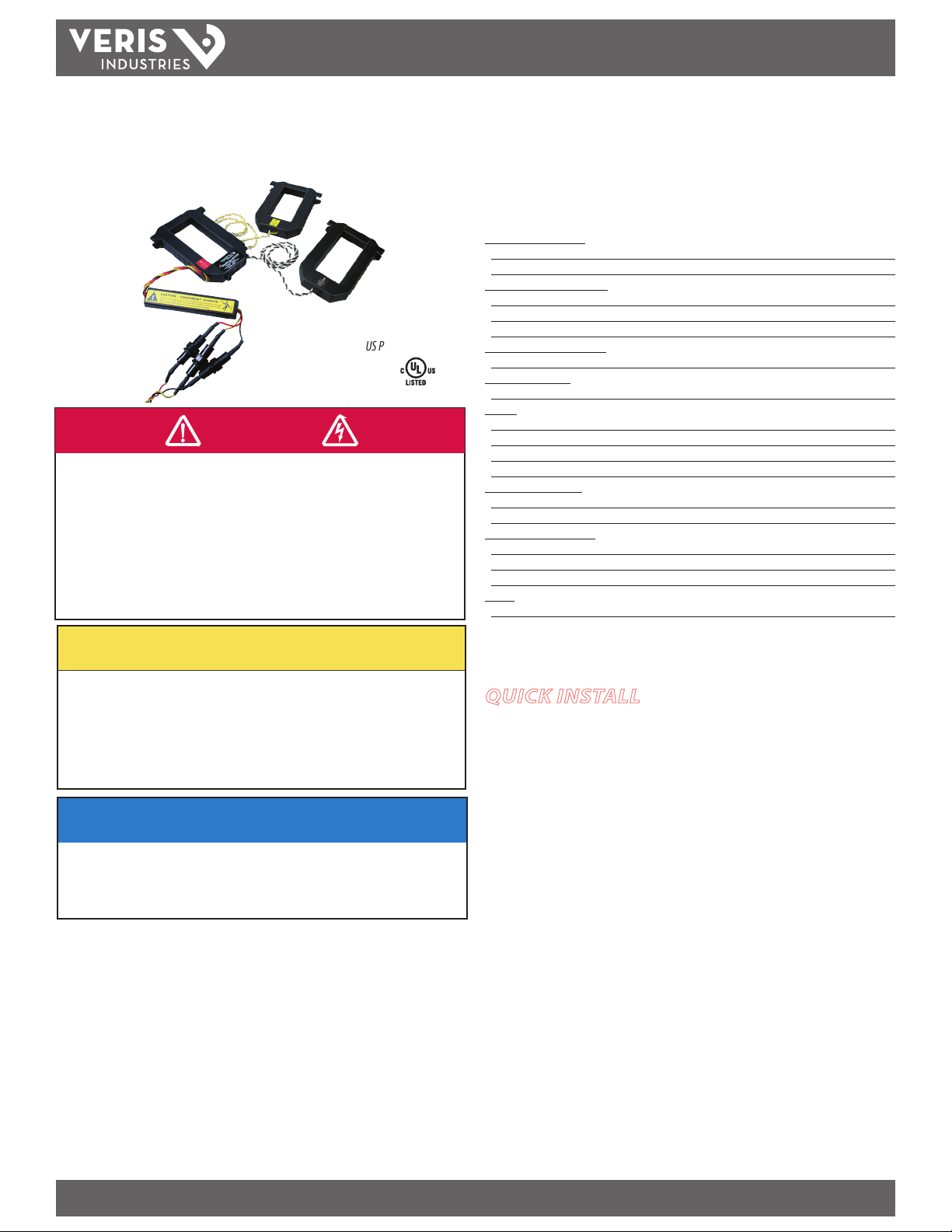
ENERCEPT
TM
H8051/H8053
Pulse Output kWh Transducers
US Patent No. 6,373,238
IND. CONT. EQ.
UL 508
DANGER
HAZARD OF ELECTRIC SHOCK, EXPLOSION, OR ARC FLASH
• Follow safe electrical work practices. See NFPA 70E in the USA, or applicable local codes.
• This equipment must only be installed and serviced by qualified electrical personnel.
• Read, understand and follow the instructions before installing this product.
• Turn off all power supplying equipment before working on or inside the equipment.
• Use a properly rated voltage sensing device to confirm power is off.
DO NOT DEPEND ON THIS PRODUCT FOR VOLTAGE INDICATION
• Only install this product on insulated conductors.
Failure to follow these instructions will result in death or serious injury.
Installer’s Specifications
Measurement A ccuracy:
Syste m
Accuracy ±1% of reading from 10% to 100% of the rated current*
Type of Measurement
Input Voltage Characteristics:
Measured
Frequency Range 50/60 Hz
Fuses 1/2A, 600VAC, 200 kAIC
Input Current Characteristics:
Maximum
Meter Current Draw:
Output:
Max.
Field Selectable Pulse Rate 1, 0.5, 0.25, or 0.1 kWh/pulse
Pulse Width 200 msec
Mechanical Conditions:
CT
Internal Isolation 2000VAC RMS
Environmental Conditions:
Operating
Storage
Operating
Safety:
US
AC Voltage 208-480 VAC
Primary Current 100, 300, 400, 800, 1600, or 2400A**
Maximum 60mA AC
Pulse N.O. Opto-Fet
Pulse Outpu t Current 100mA@24VAC/DC
Case Isolation 600VAC
Temperature Range 0° to 60°C (32 ° to 140°F)
Temperature Range -40° to 70°C (-40° to 15 8°F)
Humidity Range <95% RH non-condensing
and Canada (cULus) UL508 (open ty pe device)
One or three phase AC system
* Meter accuracy specied with conduc tors centered in the CT window.
CAUTION
** For amperages greater than 2400A, see App Note VN19, www.veris.com/applicationnotes.aspx
RISK OF EQUIPMENT DAMAGE
• Enercept meters are rated for use at 50-60Hz. Do not connect this product to circuits with
high harmonic energy, such as Variable Speed Drives (a.k.a. Variable Frequency Drives,
Adjustable Frequency Drives) or similar sources, as these may permanently damage the
product.
Failure to follow these instructions can result in overheating and permanent
equipment damage.
QUICK INSTALL
Disconnect and lock out power to the enclosure containing the
conductor before installation.
1. Set the pulse rate switches located on the bottom of the CT(s).
2. Connect the voltage leads to the source to be monitored.
NOTICE
• This product is not intended for life or safety applications.
• Do not install this product in hazardous or classified locations.
• The installer is responsible for conformance to all applicable codes.
• Mount this product inside a suitable fire and electrical enclosure.
FCC PART 15 INFORMATION
NOTE: This equipment has been tested by the manufacturer and found
to comply with the limits for a class A digital device, pursuant to part
15 of the FCC Rules. These limits are designed to provide reasonable
protection against harmful interference when the equipment is
operated in a commercial environment. This equipment generates,
uses, and can radiate radio frequency energy and, if not installed and
used in accordance with the instruction manual, may cause harmful
interference to radio communications. Operation of this equipment in
a residential area is likely to cause harmful interference in which case
Modifications to this product without the express authorization of
Veris Industries nullify this statement.
For use in a Pollu tion Degree 2 or bet ter environment only. A Pollut ion Degree 2 environme nt must
control conductive pollution and the possibility of condensation or high humidity. Consider the
enclosure, t he correct use of ven tilation, thermal pro perties of the equ ipment, and the relatio nship
with the env ironment. Installat ion category: CAT II or C AT III
Z201659-0N PAGE 1 12112
Alta Labs, Enercep t, Enspector, Hawkeye, Trustat, Veris, and the Veris ‘ V’ logo are trademark s or registered tradema rks of Veris Industries, L.L .C. in the USA and/or othe r countries.
3. Snap the CT(s) onto the conductor (observe color matching).
4. Connect the pulse output wires (observe polarity).
Page 2
TM
A
B
E
F
C
D
B
E
F
C
D
A
A
B
E
C
F
D
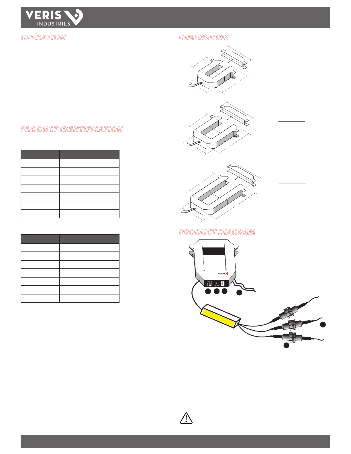
SMALL
100/300 Amp
MEDIUM
400/800 Amp
LARGE
800/1600/2400 Amp
A = 3.8" (96 mm)
B = 1.2" (30 mm)
C = 1.3" (31 mm)
D = 1.2" (30 mm)
E = 4.0" (100 mm)
F = 4.8" (121 mm)
A = 4.9" (125 mm)
B = 2.9" (73 mm)
C = 2.5" (62 mm)
D = 1.2" (30 mm)
E = 5.2" (132 mm)
F = 6.0" (151 mm)
A = 4.9" (125 mm)
B = 5.5" (139 mm)
C = 2.5" (62 mm)
D = 1.2" (30 mm)
E = 7.9" (201 mm)
F = 6.0" (151 mm)
H8051/H8053
INSTALLATION GUIDE
OPERATION
The H8051 and H8053 pulse output meters combine microprocessor-based kWh
transducers and high-accuracy split-core instrument grade current transformers (CTs)
in one unit. The H8051 is a single CT version designed for balanced loads, and the
H8053 is a 3-CT version for monitoring each phase. Integration of electronics lowers
hardware and installation costs. The sensors automatically detect phase reversal, so
CT load orientation is not a concern. The CTs and meters are calibrated as a set, so it is
necessary to color-match the CTs and voltage leads when installing.
These devices are used in tenant submetering, performance contrac ting, and
departmental costing applications. The 1% total system accuracy conforms to
ANSIC12.1 metering standards.
PRODUCT IDENTIFICATION
Single CT Units
MODEL MAX. AMPS CT SIZE
H8051-0100-2 100 SMALL
H8051-0300-2 300 SMALL
H8051-0400-3 400 MEDIUM
H8051-0800-3 800 MEDIUM
H8051-0800-4 800 LARGE
H8051-1600-4 1600 LARGE
H8051-2400-4 2400 LARGE
DIMENSIONS
Three-CT Units
MODEL MAX. AMPS CT SIZE
H8053-0100-2 100 SMALL
H8053-0300-2 300 SMALL
H8053-0400-3 400 MEDIUM
H8053-0800-3 800 MEDIUM
H8053-0800-4 800 LARGE
H8053-1600-4 1600 LARGE
H8053-2400-4 2400 LARGE
PRODUCT DIAGRAM
®
Enercept
5
4
3
1. Voltage Leads
2. Fuses
3. Pulse Output connector
4. Status LED: blink codes: slow green for normal operation; slow red for incorrect
wiring or low power factor (less than 0.5); fast red for max. current exceeded.
5. Pulse Rate Switches: used to set the pulse output rate.
6
2
1
Z201659-0N PAGE 2 12112
Alta Labs, Enercep t, Enspector, Hawkeye, Trustat, Veris, and the Veris ‘ V’ logo are trademark s or registered tradema rks of Veris Industries, L.L .C. in the USA and/or othe r countries.
6. External CTs: permanently attached; do not disconnect or use with other power
meters.
Color match CTs and voltage leads! Example: clamp the red
labeled CT around the power conductor connected to the
red voltage wire.
Page 3

TM
INSTALLATION
Disconnect and lock out power to the enclosure before
installation.
The Enercept meter, including the current transformers (CTs), voltage connection
fuses, and fuse pack, is permitted within electrical distribution equipment
including but not limited to panelboards, switchboards, motor control centers, and
transformers. Carefully review the equipment in which the Enercept meter will
be installed. Consider the following installation conditions during the installation
process:
Review the equipment enclosure for ventilation openings. Wires will cross
•
many of these openings in a normal installation; however, do not install
the Enercept where it will substantially block ventilation openings in the
enclosure.
• The Enercept meter and the wiring installed within a wiring space or
gutter should not exceed 75% cross sectional ll at the Enercept meter
parts as addressed in the NEC. Improper installation of Enercept meter in
the wire gutter of equipment may aect the thermal performance of the
equipment.
•
Consider the arrangement of CTs within the equipment to ensure
adequate bending radius of conductors.
• Review the arrangement and location of the CTs within the equipment.
Do not create undue strain on the conductor. A CT may require
appropriate support in order to address such a condition.
H8051/H8053
INSTALLATION GUIDE
4. Attach the pulse output wires as shown. Observe (+) and (-) polarity. Insulate any
exposed wiring.
5. Check power reading (these calculations are approximations only).
Expected power:
single-phase kW = Volts x Amps x PF / 1000
3-phase kW = Volts x Amps x 1.732 x PF / 1000
kW = Horsepower x 0.746
Seconds per pulse:
S = kWh pulse setting
seconds/pulse = (3600 x S) / kW
1. Set the DIP switches for the desired pulse rate as shown. Not all settings are
allowed for each model.
0.1 KWH PER PULSE
Not allowed on 1600A
and 2400A models
1.00
0.50
0.25
0.10
kWh/pulse
0.25 KWH PER PULSE
Not allowed on
2400A model
1.00
0.50
0.25
0.10
kWh/pulse
0.50 KWH PER PULSE
All models
1.00
0.50
0.25
0.10
kWh/pulse
1 KWH PER PULSE
All models
1.00
0.50
0.25
0.10
kWh/pulse
2. Connect the voltage leads to the conductors, at a location that is not normally
turned o. Connect voltage leads on the line side of the conductor to ensure
constant power to the meter. See the
Wiring section.
3. Snap the CT onto the conductor. If the
application can exceed 20 times the
rated CT current, use wire ties to secure
the I-bar to the CT housing. This CT
automatically detects phase reversal, so
CT load orientation is not important.
Wire tie
Z201659-0N PAGE 3 12112
Alta Labs, Enercep t, Enspector, Hawkeye, Trustat, Veris, and the Veris ‘ V’ logo are trademark s or registered tradema rks of Veris Industries, L.L .C. in the USA and/or othe r countries.
Page 4

WIRING
PULSE OUTPUT LINE
120V
120V
Black
Red
Yellow
Neutral
PULSE OUTPUT LINE
PHASE
PHASE
TM
H8051/H8053
INSTALLATION GUIDE
Model 8053 Model 8051
Typical 208/480 VAC 3Ø, 3- or 4-Wire Installation
ØB
ØA
ØC
PULSE OUTPUT LINE
PHASE
120
Neutral
120
Neutral
Cap This
Typical 240/120 VAC 1Ø, 3-Wire Installation
PULSE OUTPUT LINE
Cap This
Typical 277 VAC 1Ø, 2-Wire Installation
PULSE OUTPUT LINE
NOTE: Multiply output by 3 for
proper kWh indication
(Assuming balanced load)
NOTE: Multiply output by 2 for
proper kWh indication
(Assuming balanced load)
PULSE OUTPUT LINE
Neutral
277V
Black
277V
Red
Yellow
NOTE: Multiply output
by 2 for proper kWh
indication
Cap This
Alternative 277 VAC 1Ø, 2-Wire Installation
Cap This
Z201659-0N PAGE 4 12112
Alta Labs, Enercep t, Enspector, Hawkeye, Trustat, Veris, and the Veris ‘ V’ logo are trademark s or registered tradema rks of Veris Industries, L.L .C. in the USA and/or othe r countries.
277V
Neutral
Black
Red
Yellow
Cap This
PULSE OUTPUT LINE
NOTE: Wires are crossed through
the CT, each entering from
the opposite direction. Th is
arrangement does not require
multiplying the output data.
Page 5

TM
H8051/H8053
INSTALLATION GUIDE
NOTES
1. Insulate all output cable wires to prevent accidental contac t to high voltage
conductors.
2. Mechanically secure the output cable where it enters the electrical panel.
WARNING: After wiring the cable, remove all scraps of
wire or foil shield from the electrical panel. This could be
DANGEROUS if wire scraps come into contact with high
voltage wires!
TROUBLESHOOTING
Problem Solution
Status LED does not blink Check fuses and voltage connections. Status LED should
Readings seem highly inaccurate.
Meter goes oine when load is
switched o.
Status LED blinks red.
blink regardless of CTs, pulse output connections, and
DIP switch setting.
• CheckthateachCTisinstalledontheconductorwith
the corresponding color voltage input lead attached. In
most cases, incorrect wiring will cause the STATUS LED
to blink RED (slowly). However, a power factor lower
than 0.5 could cause the LED to blink this way, even if
the unit is installed properly.
• ItdoesnotmatterwhichsideoftheCTfacestowards
the load.
• Ifcurrentisbelow7%offullscalemaximumforthe
CT, use a smaller CT or wrap each wire through the CT
multiple times
•Ifusingthesingle-phaseH8051,useanamp-clamp
to ensure that all three phases are passing the same
approximate current. If phases are unbalanced, try the
H8053 model.
Voltage leads must be connected on the Line side of
the conductor. The power meter cannot communicate
without voltage.
• IftheLEDblinksquickly(i.e.,about5blinksintwo
seconds), then either the pulse rate settings are
incorrect or the CT used is too small.
• IftheLEDblinksslowly(i.e.,about1blinkpersecond)
the CTs are not installed on the correct conductors,
or the power factor is less than 0.5. The meter can
accurately measure these low PFs, but few loads
operate normally at such a low power factor.
• IftheLEDblinksslowly(i.e.,about1blinkper
second), the monitored load might be less than 10%
of the CT maximum ratings.
Z201659-0N PAGE 5 12112
Alta Labs, Enercep t, Enspector, Hawkeye, Trustat, Veris, and the Veris ‘ V’ logo are trademark s or registered tradema rks of Veris Industries, L.L .C. in the USA and/or othe r countries.
 Loading...