

Page 1
Catalog
August
05
Industrial Control Transformers
Class 9070
CONTENTS
Description. . . . . . . . . . . . . . . . . . . . . . . . . . . . . . . . . . . . . . . . . . . . . .Page
Product Description . . . . . . . . . . . . . . . . . . . . . . . . . . . . . . . . . . . . . . . . . . . 3
Type T Transformers . . . . . . . . . . . . . . . . . . . . . . . . . . . . . . . . . . . . . . . . . . 4
Type EO Transformers. . . . . . . . . . . . . . . . . . . . . . . . . . . . . . . . . . . . . . . . 27
Fuse Protection . . . . . . . . . . . . . . . . . . . . . . . . . . . . . . . . . . . . . . . . . . . . . 35
Type TF Transformers . . . . . . . . . . . . . . . . . . . . . . . . . . . . . . . . . . . . . . . . 42
Field Installed Fuse Options . . . . . . . . . . . . . . . . . . . . . . . . . . . . . . . . . . . 44
Application . . . . . . . . . . . . . . . . . . . . . . . . . . . . . . . . . . . . . . . . . . . . . . . . . 55
Frequently Asked Questions . . . . . . . . . . . . . . . . . . . . . . . . . . . . . . . . . . . 58
Page 2

Page 3

Industrial Control Transformers
Product Description
PRODUCT DESCRIPTION
Control power transformers from Schneider Electric set the industry standard for design innovation and
performance. They are designed with low impedance windings for excellent voltage regulation, and
can accomodate the high inrush current associated with contactors, starters, solenoids, and relays.
A variety of designs are available to meet the diverse needs of panel builders and machinery OEMs.
The versatility of our control transformer line offers unparalleled options for design engineers. We also
have one of the most extensive offering of custom products with no minimum order requirements.
We have a national network of distributors to ensure prompt delivery, including industry leading
delivery on custom products. In most cases, we can design, manufacture, and ship a custom unit in
two weeks or less.
The Global Product Offering—Type T
Type T is our most popular and complete line of control transformers. It comes with unmatched design
innovations for top performance and is manufactured using the most advanced insulating materials.
The Type T control transformer is the best choice if size and cost are of concern.
The Exceptional Regulation Offering —Type EO
Constructed with traditional materials and manufacturing processes, Type EO transformers are UL and
CSA Component Recognized. Units are designed for 55°C rise. All units are 60HZ rated, with
de-rated VA levels for 50HZ.
Transformers with Fuse Block Protection—Types TF and EOF
We offer both product lines with factory installed overcurrent protection fuse blocks.
Type TF and EOF transformers consist of two primary fuse blocks and one secondary fuse block, a
configuration that meets the majority of overcurrent needs by panel builders and machinery OEMs.
Since the fuse blocks are pre-wired and mounted on top of the transformer, the Type TF and EOF
transformers have the same footprint as the Type T and Type EO units, respectively. This design frees
up space normally used for separate fuse blocks
We also have an extensive fuse block offering for custom applications. See the overcurrent section of
this catalog for full details.
Leaded Control Transformer Line
Schneider Electric offers transformers with internally pre-wired 24-inch primary and secondary leads,
instead of terminal boards, to make installation easier and faster for many applications. These are only
available for single voltage primary and single voltage secondary applications.
MultiTap
Schneider Electric offers Type T and Type EO transformers in the MultiTap version. The MultiTap
control transformer was designed to respond to the increased need for voltage and stock flexibility. It
combines multiple primary voltages with one or more secondary voltages, all in a single transfomer.
The most flexible MultiTap voltage is the Universal, available on the Type T product line only. It allows
for standard primary voltages of 208 to 600V and 110, 115, or 120V secondary voltages.
08/2005
© 1999–2005 Schneider Electric All Rights Reserved
3
Page 4
Industrial Control Transformers
Type T Transformers
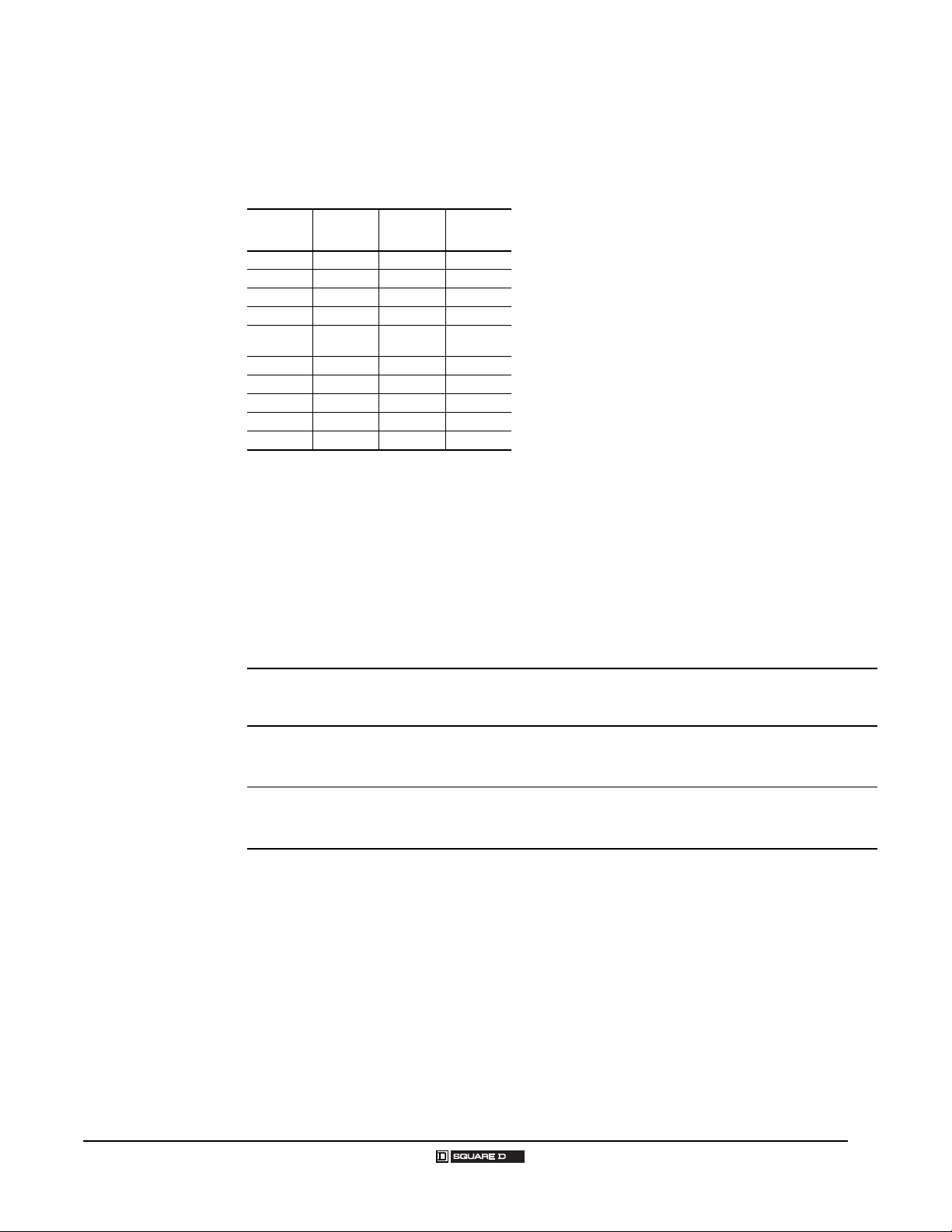
TYPE T TRANSFORMERS
Type T VA Ratings
UL, cUL, CSA and NOM VA
Rating
25 25
50 50
75 75
100 100
150 150
200 200
250 160
300 200
350 250
500 300
750 500
1000 630
1500 1000
2000 1500
3000 2000
5000 3000
CE
VA Rating
Type T Listings
Listing File VA Range
UL E61239, Guide XPTQ2 25–5000
cUL E61239 1500–5000
CSA LR37055, Guide 184-N-90 25–1000
947923, EN 61 558/01.89 (TUV
EN
ref: 00941-RAG/sg
E9371495E01)
9579078, EN 61 558/01.89 (TUV
ref: 00941-RAG/sg
E9471921E01)
9579078, EN 61 558/01.89 (TUV
ref: 00941-RAG/sg
E9471921.02E01)
25–200
250–1000
1500–3000
The Type T units are designed for the global market and are the best choice
when size and cost are of concern. This is our most popular and complete
offering of industrial control transformers. The following features are
included:
• 50/60 Hz rated
• Customer installed accessories (Finger-Safe covers, fuse blocks, fuse
clips)
• Type T transformers are designed with various temperature classes:
— 25–150 VA with a 55° C temperature rise, 105° C insulation
— 200–350 VA with a 80° C temperature rise, 130° C insulation
— 500–5000 VA with a 115° C temperature rise, 180° C insulation
Schneider Electric manufactures a wide variety of voltage combinations for
control transformers. The voltage combinations are expressed as “Voltage
Codes”, and are embedded within the catalog number of the transformer.
Standard codes are listed. If the voltage combination you need is not listed,
please call your Schneider Electric distributor for assistance.
CE Marking
Industrial control transformers (ICTs) entering the European Union (EU)
after January 1, 1997 are required by EU standards to have CE marking or
Declaration of Conformity to CE. EU documentation requires compliance
with specification EN 61 558 of the Low Voltage Directive. Type T ICTs from
Schneider Electric comply with this specification and are third party tested to
TÜV standards, which adhere to, and are accepted by, EU standards. A
Declaration of Conformity for all Type T units is available upon request.
Because of different overload criteria in the CE specification,
Schneider Elecric dual rates these transformers for UL VA, cUL VA, CSA
VA, NOM VA and CE VA ratings (see “Type T VA Ratings” table). Because
they are widely used with control circuit panels, ICTs are also required to
comply with EN 60 204 and EN 61 558 in these applications. The Type T
transformer line complies with EN 60 204 when Fingersafe
installed.
For more information regarding CE marking, please contact your local
Schneider Electric field sales office.
®
covers are
4
© 1999–2005 Schneider Electric All Rights Reserved 08/2005
Page 5
Selection Guide
Industrial Control Transformers
Type T Transformers
Example:
This example assumes the following:
• Two NEMA size 0 contactors do not start together, but one
could be ON when the other starts.
• One NEMA size 2 contactor can start with either of the
other contactors.
• One pilot light at 2 VA
1. VA and inrush are:
NEMA 0: sealed 27 VA; inrush 245 VA
NEMA 2: sealed 37 VA; inrush 311 VA; pilot light 2 VA
2. Total VA: 27 + 27 + 37 + 2 = 93 VA
3. Total inrush VA: 245 + 311 + 27 + 2 = 582 VA
4. From Regulation Chart for Type T at right below:
100 VA minimum unit; inrush 499 VA will not work at 90%
150 VA (next standard size); inrush 666 VA will work at 95%
1. Determine inrush and sealed VA of each coil in the control circuit and VA
of all other components.
2. Total all sealed VA of all operating coils and other loads VA (determines
minimal VA size required for the circuit).
3. Total the inrush VA of all coils that are starting at the same time and all
loads and coils that are running (using the regulation chart to give
possible units to be used).
4. Take VA size from step 2, go to standard VA size in chart below. Make
sure inrush VA from chart is greater than total VA from step 3. If not, go
to next larger VA size and repeat.
If your supply voltage is stable and fluctuates less than 5%, we recommend
you use the 90% secondary voltage column. If your supply voltage is not
stable and fluctuates more than 10%, we recommend you use the 95%
secondary voltage column. We recommend that you never use the 85%
secondary voltage column since magnetic devices lose life expectancy if
they are continuously started at 85% of rated voltage.
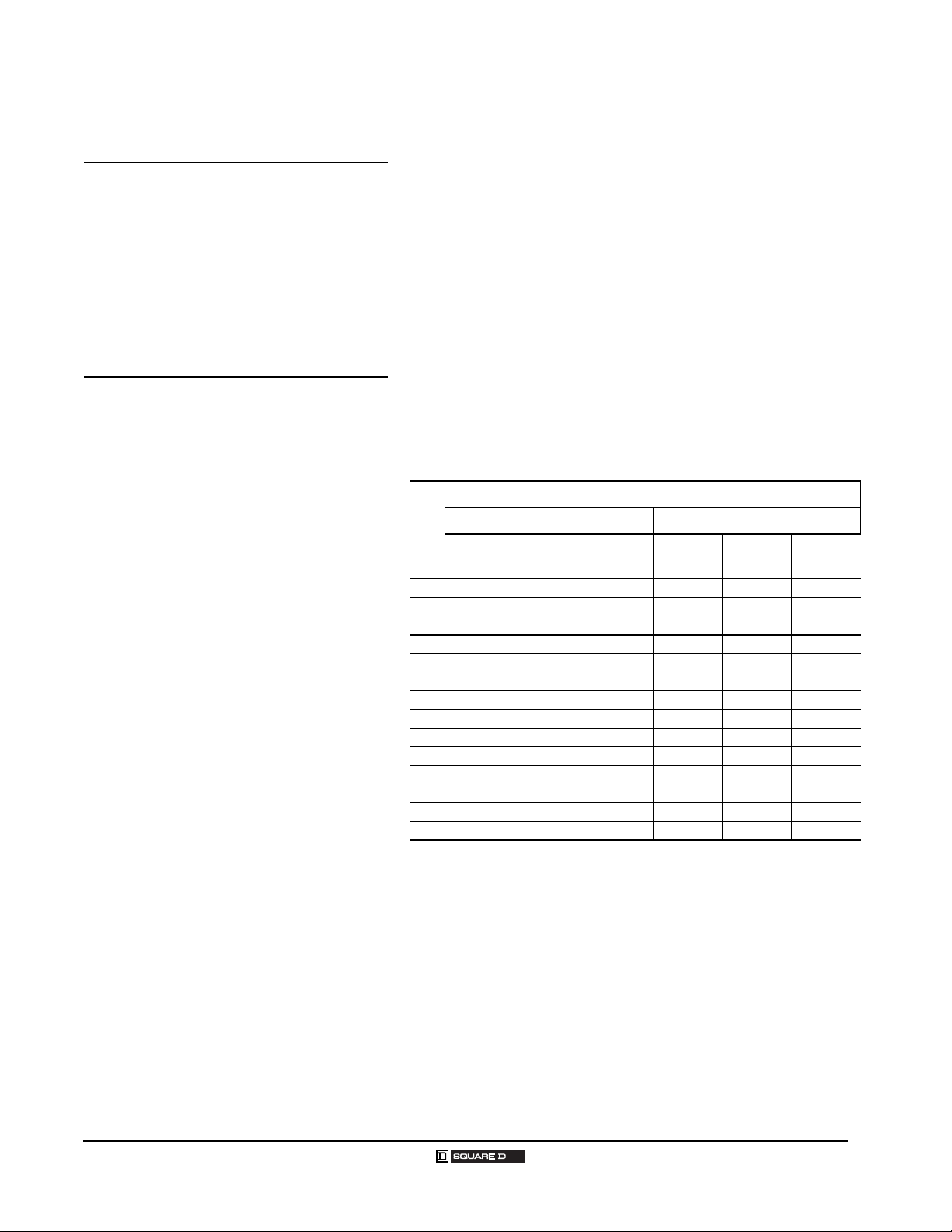
Regulation Chart for Type T
Secondary Voltage
VA
Inrush UL VA at 20% Power Factor Inrush UL VA at 40% Power Factor
95% 90% 85% 95% 90% 85%
50 193 266 339 151 215 282
75 271 396 520 210 318 430
100 339 499 659 266 404 549
150 666 893 1120 529 731 942
200 588 815 1041 459 659 866
250 1416 1910 2388 1057 1494 1936
300 1634 2184 2709 1194 1681 2169
350 1894 2592 3261 1392 2005 2621
500 3197 4104 4981 2374 3195 4019
750 3770 5515 7231 2887 4391 5945
1000 6587 9079 11430 4706 6886 9051
1500 19324 23983 28607 15066 19361 23756
2000 31384 38777 46161 24794 31630 38667
3000 26539 39934 52713 19355 30721 42216
5000 53111 85265 116277 39368 66309 93882
08/2005
© 1999–2005 Schneider Electric All Rights Reserved
5
Page 6
Industrial Control Transformers
Type T Transformers
Use the following table to quickly find a Type T transformer for a 120 volt load for your specific application. First, find your source
and load voltages. Then, go to the indicated pages for details on the transformer(s) matching those voltages.
Type T Transformers for 120 Volt Loads
Source
Voltage
110 110 D24, D55 9, 13 277 115 D18 11 440 110/220 D31 13
110 220 D55 13 277 120 D4, D60 9, 14 460 95 D32, D50 11, 12
110 110/220 D55 13 277 240 D60 14 460 115
115 115 D24, D55 9, 13 277 120/240 D60 14 460 125 D50 12
115 230 D55 13 364 85 D50 12 460 230 D31 13
115 115/230 D55 13 364 100 D50 12 460 115/230 D31 13
120 120 D24, D55 9, 13 364 110 D50 12 480 99 D50 12
120 240 D55 13 380 91 D50 12 480 100 D32 11
120 120/240 D55 13 380 95 D18 11 480 120
190 110 D95 11 380 110 D6, D50 9, 12 480 130 D50 12
200 115 D93, D95 9, 11 380 115 D18, D33 11, 14 480 240 D31 13
208 85 D50 12 380 120 D40, D50 11, 12 480 120/240 D31 13
208 95 D18 11 380 230 D33 14 500 85 D50 12
208 100 D50 12 380 115/230 D33 14 500 100 D50 12
208 110 D50 12 400 95 D50 12 500 110 D50 12
208 115 D20, D18 10, 11 400 115 D33 14 550 90 D32 11
208 120 D3, D40 9, 11 400 120 D103, D50 9, 12 550 91 D50 12
220 90 D32 11 400 125 D50 12 550 110
220 91 D50 12 400 230 D33 14 550 120 D50 12
220 110
220 120 D50 12 415 110 D17 9 550 110/220 D37 14
220 220 D31, D55 13 415 115 D33 14 575 95 D32, D50 11, 12
220 110/220 D31, D55 13 415 230 D33 14 550 110/220 D37 14
230 95 D32, D50 11, 12 415 115/230 D33 14 575 95 D32, D50 11, 12
230 115
230 125 D50 12 416 120 D40, D50 11, 12 575 125 D50 12
230 230 D31, D55 13 416 130 D50 12 575 230 D37 14
230 115/230 D31, D55 13 420 85 D50 12 575 115/230 D37 14
240 99 D50 12 420 100 D50 12 600 99 D50 12
240 100 D32 11 420 110 D50 12 600 100 D32 11
240 120
240 130 D50 12 440 91 D50 12 600 130 D50 12
240 240 D31, D55 13 440 110
240 120/240 D31, D55 13 440 120 D50 12 600 120/240 D37 14
277 95 D18 11 440 220 D31 13
Load
Voltage
Voltage
Code(s)
D1, D32,
D95, D50,
D31, D55
D1, D20,
D32, D95,
D50, D31,
D55
D1, D32,
D40, D95,
D50, D31,
D55
Go To
Page(s)
8, 11, 12,
13
8, 10, 11,
12, 13
8, 11, 12,
13
Source
Voltage
400 115/230 D33 14 550 220 D37 14
416 99 D50 12 575 115
440 90 D32 11 600 120
Load
Voltage
Voltage
Code(s)
D1, D32,
D95, D50,
D31
Go To
Page(s)
8, 11, 12,
13
Source
Voltage
600 240 D37 14
Load
Voltage
Voltage
Code(s)
D1, D20,
D32, D95,
D50, D31
D1, D32,
D40, D95,
D50, D31
D5, D32,
D50, D37
D5, D32,
D50, D37
D5, D32,
D50, D37
Go To
Page(s)
8, 10, 11,
12, 13
8, 11, 12,
13
9, 11, 12,
14
9, 11, 12,
14
9, 11, 12,
14
6
© 1999–2005 Schneider Electric All Rights Reserved 08/2005
Page 7
Industrial Control Transformers
Type T Transformers
Use the following table to quickly find a Type T transformer for a 24 volt load for your specific
application. First, find your source and load voltages. Then, go to the indicated pages for details on the
transformer(s) matching those voltages.
Type T Transformers for 24 Volt Loads
Source
Voltage
115 24 D89 15
120 24 D23, D7 15, 16
208 24 D14, D19 16, 17
230 24 D89, D112 15, 16
240 24
277 24 D25, D19 16, 17
380 24 D88, D19 16, 17
460 24 D92 15
480 24 D2, D19 15, 17
600 24 D16 16
Load
Voltage
Voltage
Code(s)
D2, D23,
D19
Go To
Page(s)
15, 17
Custom-Built Type T Transformers
For voltage combinations not listed, Schneider Electric offers custom-built Type T transformers. Type T
units are limited to the following:
Primary Voltage Range: 120 to 600 Volts
Secondary Voltage Range: 12 to 277 Volts (25 to 1000VA)
12/24 to 277 Volts (25 to 2000VA)
24/48 to 277 Volts (25 to 5000VA)
Single
Dual
Single Dual
25VA to
5000VA
25VA to
5000VA
25VA to
5000VA
25VA to
5000VA
One Primary Tap
(two voltages)
Voltages with 20%
25VA to 5000VA
Voltages greater then
20% 25VA to 3000VA
Voltages with 20%
25VA to 5000VA
Voltages greater then
20% 25VA to 3000VA
Two Primary Taps
(three voltages
Voltages with 20%
25VA to 5000VA
Voltages greater then
20% 25VA to 3000VA
Voltages with 20%
25VA to 5000VA
Voltages greater then
20% 25VA to 3000VA
Three Primary
Taps
(four voltages)
25VA to 3000VA 25VA to 3000VA
25VA to 3000VA 25VA to 3000VA
Four Primary
Taps
(five Voltages)
Schneider Electric also offers Secondary Tapped units and Multiple Winding Secondary units. Since
the sizing of these units are determined by the secondary loading, they are limited to 3000VA total
secondary capacity in the 9070 Type T product.
To request a price quotation from Schneider Electric for a custom-built Type T transformer, use the
price quote sheet on page 26.
08/2005
© 1999–2005 Schneider Electric All Rights Reserved
7
Page 8
Industrial Control Transformers
Type T Transformers
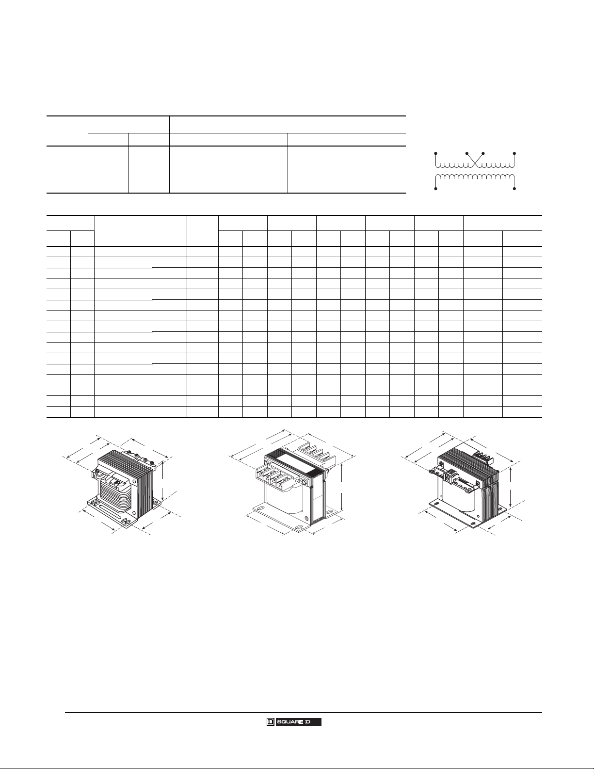
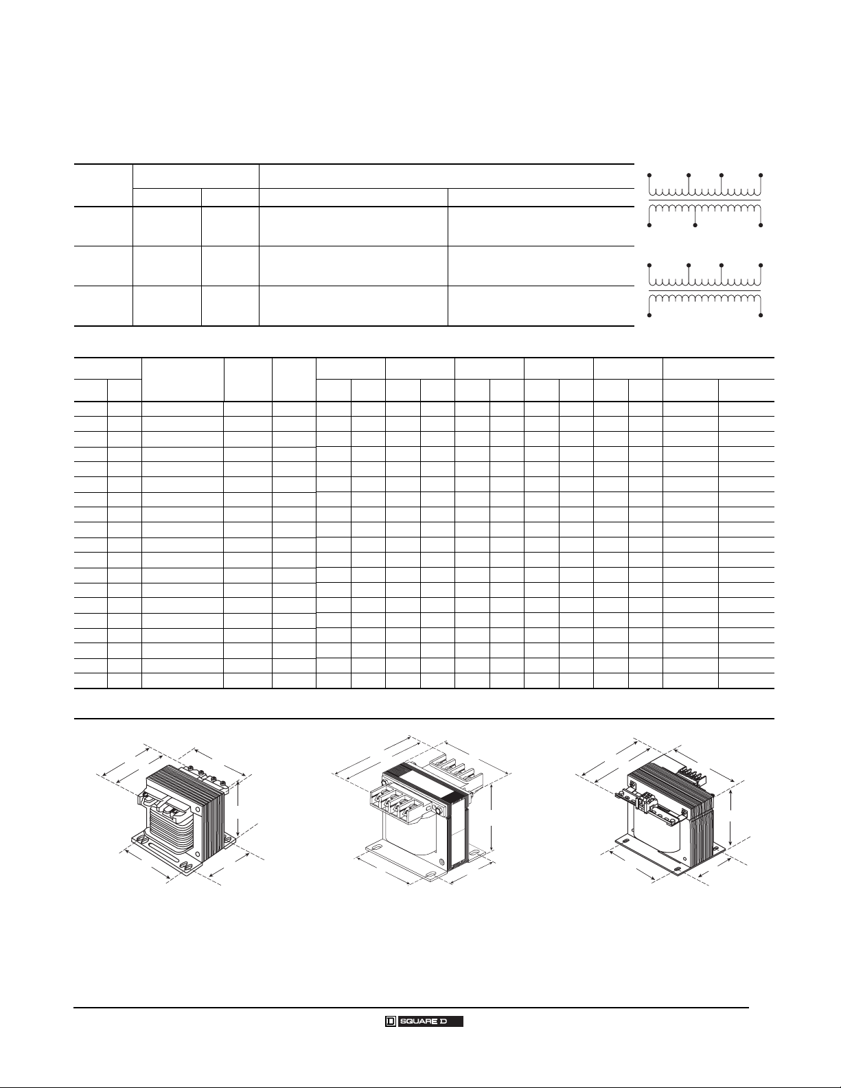
120 Volt Control Secondary
Voltage and Connection Options
Voltage
Code
D1
Dimensions
VA
UL CE IN
25 25 9070T25D1 1 I 3.09 79 3.00 76 2.58 66 2.00 51 2.50 64 0.20 x 0.38 5 x 10
50 50 9070T50D1 1 I 3.09 79 3.00 76 2.58 66 2.00 51 2.50 64 0.20 x 0.38 5 x 10
75 75 9070T75D1 1 I 3.34 85 3.38 86 2.89 73 2.38 61 2.81 71 0.20 x 0.48 5 x 12
100 100 9070T100D1 1 I 3.34 85 3.38 86 2.89 73 2.38 61 2.81 71 0.20 x 0.48 5 x 12
150 150 9070T150D1 1 I 3.59 91 3.75 95 3.20 81 2.88 73 3.13 80 0.20 x 0.38 5 x 10
200 200 9070T200D1 1 I 3.59 91 3.75 95 3.20 81 2.88 73 3.13 80 0.20 x 0.38 5 x 10
250 160 9070T250D1 2 I 5.30 135 3.75 95 3.21 82 2.88 73 3.13 80 0.20 x 0.38 5 x 10
300 200 9070T300D1 2 I 4.74 120 4.50 114 3.84 98 2.56 65 3.75 95 0.20 x 0.38 5 x 10
350 250 9070T350D1 2 I 5.11 130 4.50 114 3.84 98 3.00 76 3.75 95 0.20 x 0.38 5 x 10
500 300 9070T500D1 2 I 5.49 139 4.50 114 3.84 98 3.56 90 3.75 95 0.20 x 0.38 5 x 10
750 500 9070T750D1 2 I 5.61 143 5.25 133 4.51 115 3.43 87 4.38 111 0.28 x 0.56 7 x 14
1000 630 9070T1000D1 2 I 6.30 160 5.25 133 4.51 115 4.31 109 4.38 111 0.28 x 0.56 7 x 14
1500 1000 9070T1500D1 2 I 5.92 150 7.06 179 6.17 157 4.13 105 5.81 148 0.28 x 0.56 7 x 14
2000 1500 9070T2000D1 2 I 7.17 182 7.06 179 6.17 157 4.56 116 5.81 148 0.28 x 0.56 7 x 14
3000 2000 9070T3000D1 3 I 7.24 184 9.00 229 8.75 222 4.63 118 7.63 194 0.44 x 1.13 11 x 29
5000 3000 9070T5000D1 3 I 9.15 232 9.00 229 8.75 222 6.56 167 7.63 194 0.44 x 1.13 11 x 29
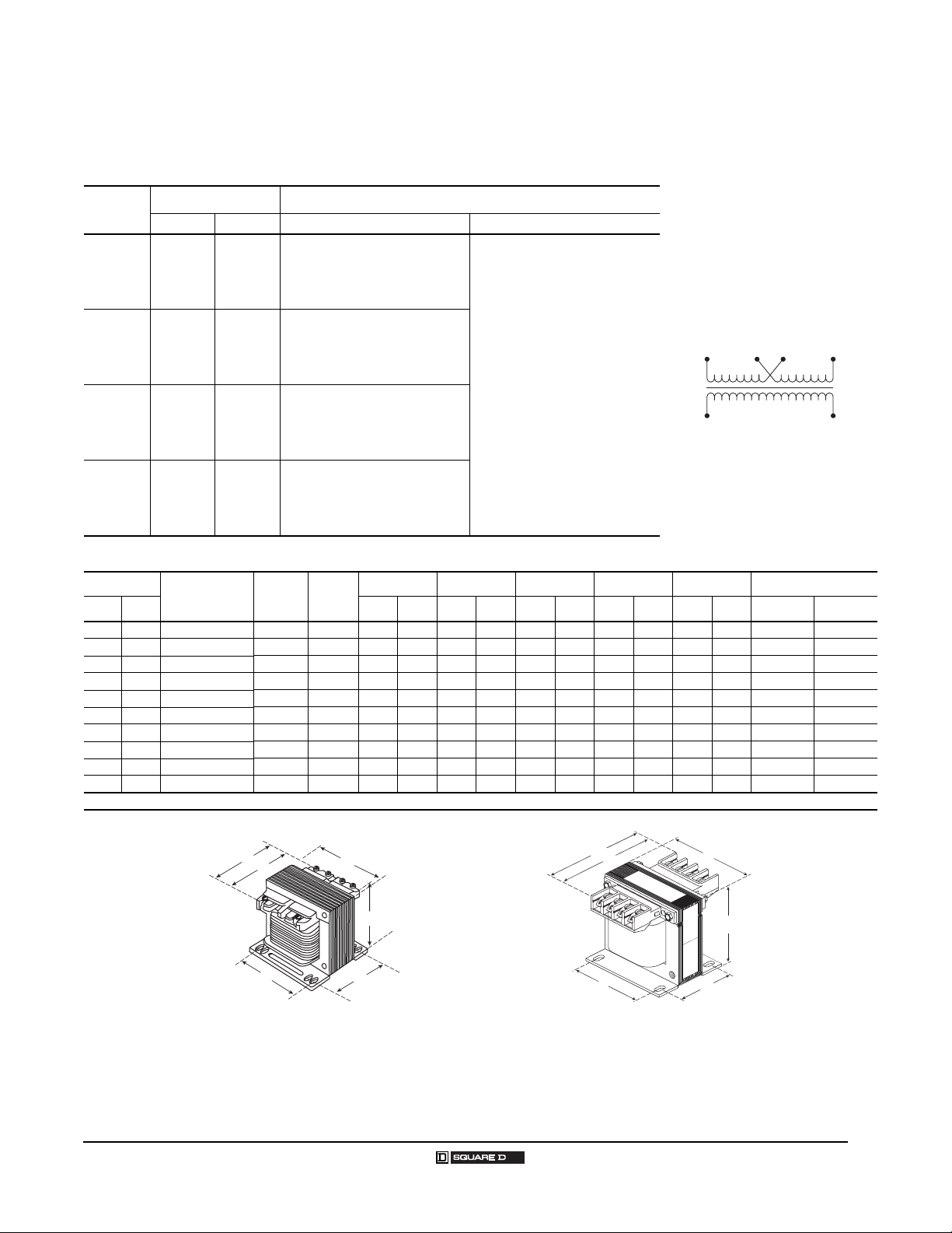
Voltages Connections
Primary Secondary Primary Secondary
220 x 440
230 x 460
240 x 480
Catalog
Number
220/230/240 V:Connect to H1 and H4
110
115
120
440/460/480 V:Connect to H1 and H4
Figure
Jumper H1 with H3
Jumper H2 with H4
Jumper H2 with H3
Acc.
Key
Connect to X1 and X2
ABCE F Slots
mm
IN
mm
IN
mm
H1
X2 X1
IN
mm
IN
mm
H2H3 H4
IN
mm
D
D
A
F
B
C
E
A
F
Figure 2Figure 1
B
C
E
D
A
F
B
E
Figure 3
8
© 1999–2005 Schneider Electric All Rights Reserved 08/2005
C
Page 9
Industrial Control Transformers
Type T Transformers
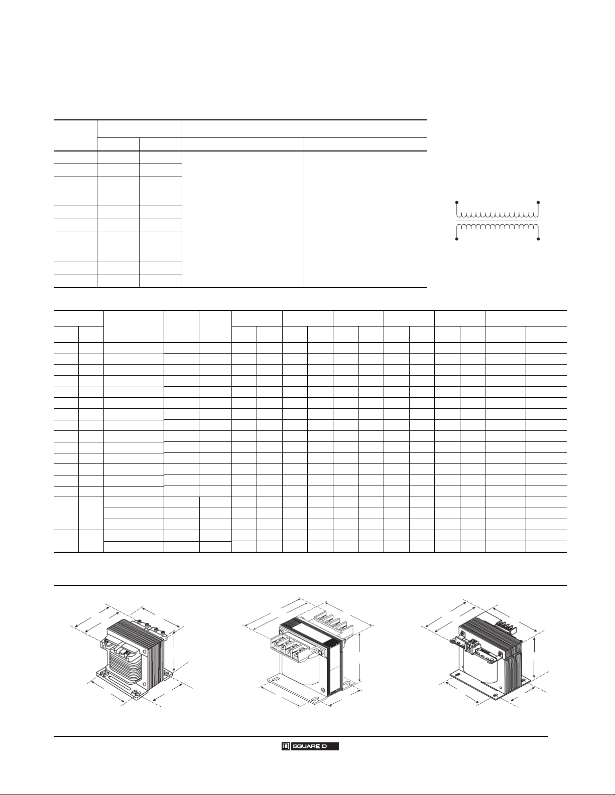
120 Volt Control Secondary
Voltage and Connection Options
Voltage
Code
D3 208 120
D4 277 120
D5
D6 380 110
D17 415 110
D24
D93 200 115
D103 400 120
Dimensions
VA
UL CE IN
25 25 9070T25t 1 I 3.09 79 3.00 76 2.58 66 2.00 51 2.50 64 0.20 x 0.38 5 x 10
50 50 9070T50t 1 I 3.09 79 3.00 76 2.58 66 2.00 51 2.50 64 0.20 x 0.38 5 x 10
75 75 9070T75t 1 I 3.34 85 3.38 86 2.89 73 2.38 61 2.81 71 0.20 x 0.48 5 x 12
100 100 9070T100t 1 I 3.34 85 3.38 86 2.89 73 2.38 61 2.81 71 0.20 x 0.48 5 x 12
150 150 9070T150t 1 I 3.59 91 3.75 95 3.20 81 2.88 73 3.13 80 0.20 x 0.38 5 x 10
200 200 9070T200t 1 I 3.59 91 3.75 95 3.20 81 2.88 73 3.13 80 0.20 x 0.38 5 x 10
250 160 9070T250t 2 I 5.301353.75953.21822.88733.13800.20 x 0.385 x 10
300 200 9070T300t 2 I 4.74 120 4.50 114 3.84 98 2.56 65 3.75 95 0.20 x 0.38 5 x 10
350 250 9070T350t 2 I 5.11 130 4.50 114 3.84 98 3.00 76 3.75 95 0.20 x 0.38 5 x 10
500 300 9070T500t 2 I 5.49 139 4.50 114 3.84 98 3.56 90 3.75 95 0.20 x 0.38 5 x 10
750 500 9070T750t 2 I 5.61 143 5.25 133 4.51 115 3.43 87 4.38 111 0.28 x 0.56 7 x 14
1000 630 9070T1000t 2 I 6.30 160 5.25 133 4.51 115 4.31 109 4.38 111 0.28 x 0.56 7 x 14
1500 1000 9070T1500t 2 I 5.92 150 7.06 179 6.17 157 4.13 105 5.81 148 0.28 x 0.56 7 x 14
2000 1500 9070T2000t 2 I 7.17 182 7.06 179 6.17 157 4.56 116 5.81 148 0.28 x 0.56 7 x 14
3000 2000
5000 3000
1
Complete the catalog number by replacing the t with the correct Voltage Code from the “Voltage and Connection Options” table above.
2
Complete the catalog number by replacing the t with Voltage Code D3 or D4 from the “Voltage and Connection Options” table above.
3
Complete the catalog number by replacing the t with Voltage Code D5, D6, D17, D93, or D103 from the “Voltage and Connection Options” table above.
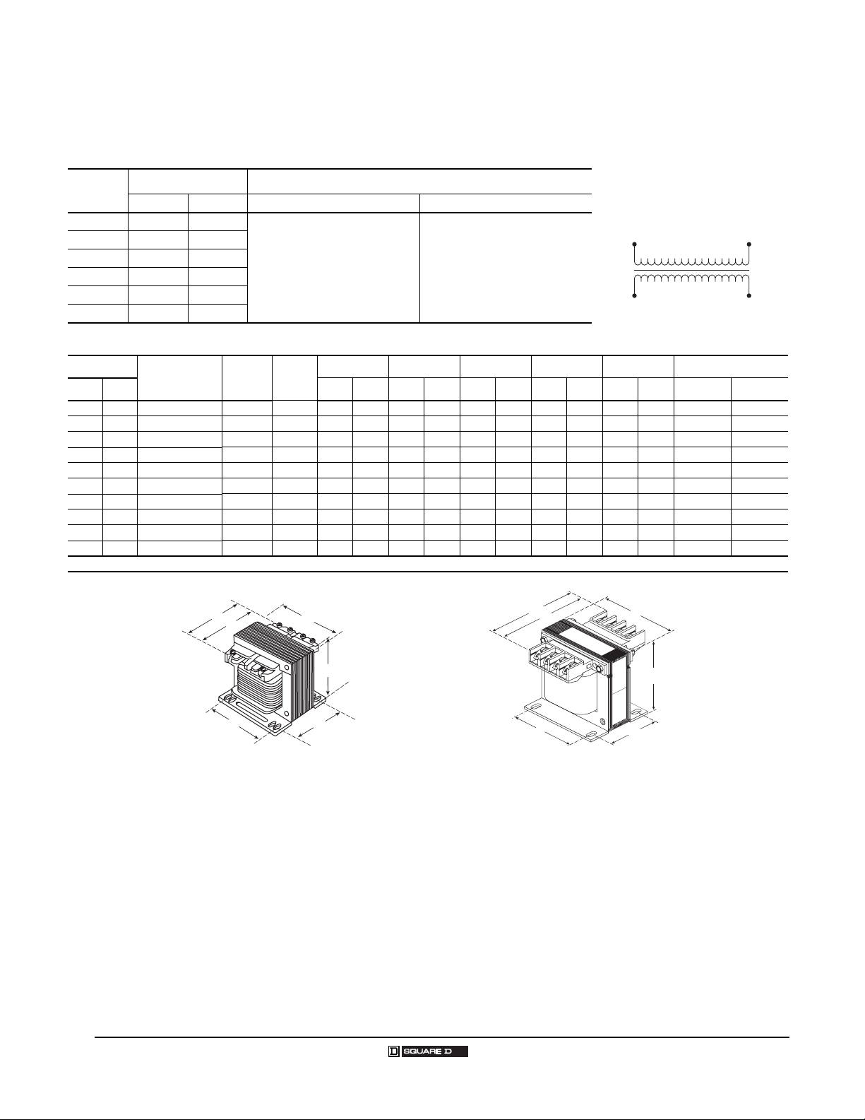
Voltages Connections
Primary Secondary Primary Secondary
550
575
600
110
115
120
Catalog
Number
9070T3000t
9070T3000t
9070T3000D24 3 N/A 8.08 205 9.00 229 8.75 222 4.63 118 7.63 194 0.44 x 1.13 11 x 29
9070T5000t 3 I 9.15 232 9.00 229 8.75 222 6.56 167 7.63 194 0.44 x 1.13 11 x 29
9070T5000D24 3 N/A 9.99 254 9.00 229 8.75 222 6.56 167 7.63 194 0.44 x 1.13 11 x 29
110
115
120
Connect to H1 and H2 Connect to X1 and X2
110
115
120
Figure
1
2
3
Acc.
Key
2 I 6.38 162 9.00 229 7.63 194 4.63 118 7.63 194 0.44 x 1.13 11 x 29
3 I 7.24 184 9.00 229 8.75 222 4.63 118 7.63 194 0.44 x 1.13 11 x 29
ABCEF Slots
mm
IN
mm
IN
mm
IN
mm
H1
X2 X1
IN
mm
H2
IN
mm
08/2005
D
D
A
F
B
C
E
A
F
Figure 2Figure 1
B
C
E
D
A
F
B
C
E
Figure 3
9
© 1999–2005 Schneider Electric All Rights Reserved
Page 10
Industrial Control Transformers
Type T MultiTap Transformers
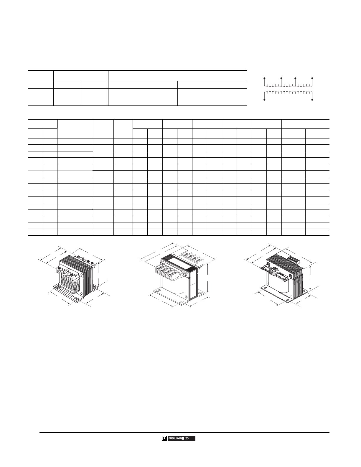
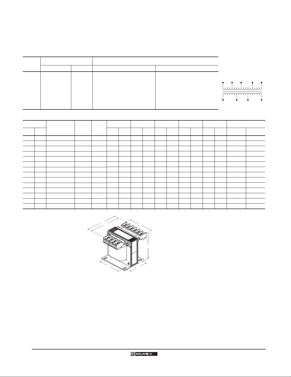
120 Volt Control Secondary
Voltage and Connection Options
Voltage
Code
D20 208/230/460 115
Dimensions
VA
UL CE IN
25 25 9070T25D20 1 II 3.09 79 3.00 76 2.58 66 2.00 51 2.50 64 0.20 x 0.38 5 x 10
50 50 9070T50D20 1 II 3.34 85 3.38 86 2.89 73 2.38 61 2.81 71 0.20 x 0.48 5 x 12
75 75 9070T75D20 1 II 3.34 85 3.38 86 2.89 73 2.38 61 2.81 71 0.20 x 0.48 5 x 12
100 100 9070T100D20 1 II 3.59 91 3.75 95 3.20 81 2.88 73 3.13 80 0.20 x 0.38 5 x 10
150 150 9070T150D20 1 II 3.59 91 3.75 95 3.20 81 2.88 73 3.13 80 0.20 x 0.38 5 x 10
200 200 9070T200D20 2 II 4.70 119 3.75 95 3.20 81 2.88 73 3.13 80 0.20 x 0.38 5 x 10
250 160 9070T250D20 2 II 4.74 120 4.50 114 3.84 98 2.56 65 3.75 95 0.20 x 0.38 5 x 10
300 200 9070T300D20 2 II 5.11 130 4.50 114 3.84 98 3.00 76 3.75 95 0.20 x 0.38 5 x 10
350 250 9070T350D20 2 II 5.49 139 4.50 114 3.84 98 3.56 90 3.75 95 0.20 x 0.38 5 x 10
500 300 9070T500D20 2 II 5.61 143 5.25 133 4.51 115 3.43 87 4.38 111 0.28 x 0.56 7 x 14
750 500 9070T750D20 2 II 6.30 160 5.25 133 4.51 115 4.31 109 4.38 111 0.28 x 0.56 7 x 14
1000 630 9070T1000D20 2 II 5.92 150 7.06 179 6.17 157 4.13 105 5.81 148 0.28 x 0.56 7 x 14
1500 1000 9070T1500D20 2 II 7.17 182 7.06 179 6.17 157 4.56 116 5.81 148 0.28 x 0.56 7 x 14
2000 1500 9070T2000D20 2 II 6.38 162 9.00 229 7.63 194 4.63 118 7.63 194 0.44 x 1.13 11 x 29
3000 2000 9070T3000D20 2 II 8.31 211 9.00 229 7.63 194 6.56 167 7.63 194 0.44 x 1.13 11 x 29
Voltages Connections
Primary Secondary Primary Secondary
208: Connect to H1 and H2
Catalog
Number
230: Connect to H1 and H3
460: Connect to H1 and H4
Figure
1
Acc.
Key
ABCE F Slots
mm
IN
Connect to X1 and X2
mm
IN
mm
H1
X2 X1
IN
mm
IN
mm
H3 H4H2
IN
mm
D
D
A
F
B
C
E
A
F
Figure 2Figure 1
B
C
E
D
A
F
B
C
E
Figure 3
10
© 1999–2005 Schneider Electric All Rights Reserved 08/2005
Page 11
Industrial Control Transformers
Type T MultiTap Transformers
120 Volt Secondary
Voltage and Connection Options
Voltage
Code
D18 208/277/380 95/115
D32
D95
Dimensions
VA
UL CE IN
25 25 9070T25t 1 II 3.09793.00762.58662.00512.50640.20 x 0.385 x 10
50 50 9070T50t 1 II 3.34853.38862.89732.38612.81710.20 x 0.485 x 12
75 75 9070T75D32 1 II 3.34 85 3.38 86 2.89 73 2.38 61 2.81 71 0.20 x 0.48 5 x 12
75 75 9070T75t
100 100 9070T100t 1 II 3.59913.75953.20812.88733.13800.20 x 0.385 x 10
150 150 9070T150D32 2 II 4.70 119 3.75 95 3.20 81 2.88 73 3.13 80 0.20 x 0.38 5 x 10
150 150 9070T150t
200 200 9070T200t 2 II 4.74 120 4.50 114 3.84 98 2.56 65 3.75 95 0.20 x 0.38 5 x 10
250 160 9070T250D32 2 II 5.11 130 4.50 114 3.84 98 3.00 76 3.75 95 0.20 x 0.38 5 x 10
250 160 9070T250t
300 200 9070T300D32 2 II 5.49 139 4.50 114 3.84 98 3.56 90 3.75 95 0.20 x 0.38 5 x 10
300 200 9070T300t
350 250 9070T350t 2 II 5.49 139 4.50 114 3.84 98 3.56 90 3.75 95 0.20 x 0.38 5 x 10
500 300 9070T500t 2 II 5.61 143 5.25 133 4.51 115 3.43 87 4.38 111 0.28 x 0.56 7 x 14
750 500 9070T750t 2 II 6.30 160 5.25 133 4.51 115 4.31 109 4.38 111 0.28 x 0.56 7 x 14
1000 630 9070T1000t 2 II 5.92 150 7.06 179 6.17 157 4.13 105 5.81 148 0.28 x 0.56 7 x 14
1500 1000 9070T1500t 2 II 7.17 182 7.06 179 6.17 157 4.56 116 5.81 148 0.28 x 0.56 7 x 14
2000 1500 9070T2000t 2 II 6.38 162 9.00 229 7.63 194 4.63 118 7.63 194 0.44 x 1.13 11 x 29
3000 2000 9070T3000t 3 II 9.15 232 9.00 229 8.75 222 6.56 167 7.63 194 0.44 x 1.13 11 x 29
1
Complete the catalog number by replacing the t with the correct Voltage Code from the “Voltage and Connection Options” table above.
2
Complete the catalog number by replacing the t with Voltage Code D18 or D95 from the “Voltage and Connection Options” table above.
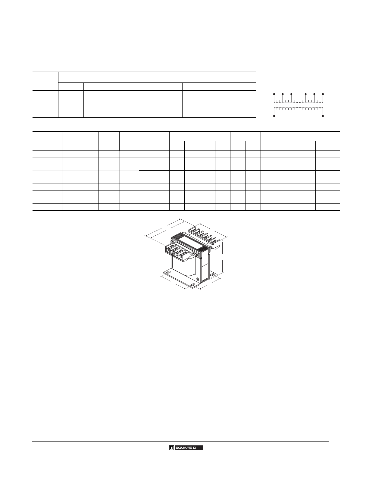
Voltages Connections
Primary Secondary Primary Secondary
220/440/550
230/460/575
240/480/600
190/220/440
200/230/460
208/240/480
Catalog
Number
2
1
2
2
2
208: Connect to H1 and H2
277: Connect to H1 and H3
380: Connect to H1 and H4
90/110
95/115
100/120
220 or 230 or 240: Connect to H1 and H2
440 or 460 or 480: Connect to H1 and H3
550 or 575 or 660: Connect to H1 and H4
110
190 or 200 or 208: Connect to H1 and H2
115
220 or 230 or 240: Connect to H1 and H3
120
440 or 460 or 480: Connect to H1 and H4
Figure
Acc.
Key
1 II 3.59913.75953.20812.88733.13800.20 x 0.385 x 10
1 II 3.59913.75953.20812.88733.13800.20 x 0.385 x 10
2 II 4.74 120 4.50 114 3.84 98 2.56 65 3.75 95 0.20 x 0.38 5 x 10
2 II 5.11 130 4.50 114 3.84 98 3.00 76 3.75 95 0.20 x 0.38 5 x 10
ABCEF Slots
mm
IN
95: Connect to X1 and X2
115: Connect to X1 and X3
90 or 95 or 100: Connect to X1 and X2
110 or 115 or 120: Connect to X1 and X3
110 or 115 or 120: Connect to X1 and X2
mm
IN
mm
IN
mm
H1
X3 X2 X1
H1
X2 X1
IN
mm
H3 H4H2
H3 H4H2
IN
mm
08/2005
D
D
A
F
B
C
E
A
F
Figure 2Figure 1
B
C
E
D
A
F
B
C
E
Figure 3
11
© 1999–2005 Schneider Electric All Rights Reserved
Page 12
Industrial Control Transformers
Type T MultiTap Transformers
Universal
Voltage and Connection Options
Voltage
Code
208/364/420/500
D50
220/380/440/550
230/400/460/575
240/416/480/600
Dimensions
VA
UL CE IN
25 25 9070T25D50 4 III 4.43 113.0 3.38 85.9 2.89 73.4 2.38 61.0 2.81 71.4 0.20 x 0.48 5 x 12
50 50 9070T50D50 4 III 4.43 113.0 3.38 85.9 2.89 73.4 2.38 61.0 2.81 71.4 0.20 x 0.48 5 x 12
75 75 9070T75D50 4 III 4.70 119.4 3.75 95.3 3.20 81.3 2.88 73.2 3.13 80.0 0.20 x 0.38 5 x 10
100 100 9070T100D50 4 III 4.70 119.4 3.75 95.3 3.20 81.3 2.88 73.2 3.13 80.0 0.20 x 0.38 5 x 10
150 150 9070T150D50 4 III 4.74 120.4 4.50 114.3 3.84 98.0 2.56 65.0 3.75 95.3 0.20 x 0.38 5 x 10
200 200 9070T200D50 4 III 5.11 129.8 4.50 114.3 3.84 98.0 3.00 76.2 3.75 95.3 0.20 x 0.38 5 x 10
250 160 9070T250D50 4 III 5.11 129.8 4.50 114.3 3.84 98.0 3.00 76.2 3.75 95.3 0.20 x 0.38 5 x 10
300 200 9070T300D50 4 III 5.49 139.4 4.50 114.3 3.84 98.0 3.56 90.4 3.75 95.3 0.20 x 0.38 5 x 10
350 250 9070T350D50 4 III 5.61 142.5 5.25 133.4 4.51 114.6 3.43 87.1 4.38 111.3 0.28 x 0.56 7 x 14
500 300 9070T500D50 4 III 5.61 142.5 5.25 133.4 4.51 114.6 3.43 87.1 4.38 111.3 0.28 x 0.56 7 x 14
750 500 9070T750D50 4 III 6.30 160.0 5.25 133.4 4.51 114.6 4.31 110.0 4.38 111.3 0.28 x 0.56 7 x 14
1000 630 9070T1000D50 4 III 5.92 150.4 7.06 179.3 6.17 156.7 4.13 104.9 5.81 147.6 0.28 x 0.56 7 x 14
1500 1000 9070T1500D50 4 III 7.17 182.1 7.06 179.3 6.17 156.7 4.56 115.8 5.81 147.6 0.28 x 0.56 7 x 14
2000 1500 9070T2000D50 4 III 6.38 162.1 9.00 228.6 7.63 193.8 4.63 117.6 7.63 193.8 0.44 x 1.13 11 x 29
Voltages Connections
Primary Secondary Primary Secondary
Catalog
Number
85/100/110
91/110/120
95/115/125
99/120/130
Figure
208 or 220 or 230 or 240:Connect to H1
364 or 380 or 400 or 416:Connect to H1
420 or 440 or 460 or 480:Connect to H1
500 or 550 or 575 or 600:Connect to H1
Acc.
Key
and H2
and H3
and H4
and H5
85 or 91 or 95 or 99: Connect to X1
100 or 110 or 115 or 120:Connect to X1
110 or 120 or 125 or 130:Connect to X1
ABCEF Slots
mm
IN
mm
IN
mm
IN
and X2
and X3
and X4
mm
H1
X4 X3 X2 X1
IN
mm
H3 H5H4H2
IN
mm
D
A
F
B
C
E
Figure 4
12
© 1999–2005 Schneider Electric All Rights Reserved 08/2005
Page 13
Industrial Control Transformers
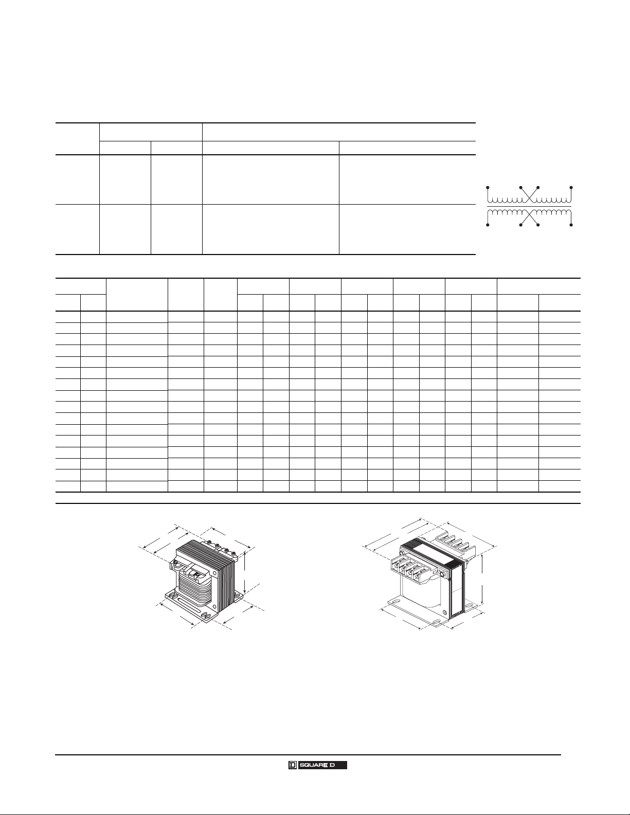
Type T Transformers with Dual Secondary
120/240 Volt Secondary
Voltage and Connection Options
Voltage
Code
D31
D55
-
Dimensions
VA
UL CE IN
25 25 9070T25t 1 I 3.09 79 3.00 76 2.58 66 2.00 51 2.50 64 0.20 x 0.38 5 x 10
50 50 9070T50t 1 I 3.09 79 3.00 76 2.58 66 2.00 51 2.50 64 0.20 x 0.38 5 x 10
75 75 9070T75t 1 I 3.34 85 3.38 86 2.89 73 2.38 61 2.81 71 0.20 x 0.48 5 x 12
100 100 9070T100t 1 I 3.34 85 3.38 86 2.89 73 2.38 61 2.81 71 0.20 x 0.48 5 x 12
150 150 9070T150t 1 I 3.59 91 3.75 95 3.20 81 2.88 73 3.13 80 0.20 x 0.38 5 x 10
200 200 9070T200t 1 I 3.59 91 3.75 95 3.20 81 2.88 73 3.13 80 0.20 x 0.38 5 x 10
250 160 9070T250t 2 I 5.301353.75953.21822.88733.13800.20 x 0.385 x 10
300 200 9070T300t 2 I 4.74 120 4.50 114 3.84 98 2.56 65 3.75 95 0.20 x 0.38 5 x 10
350 250 9070T350t 2 I 5.11 130 4.50 114 3.84 98 3.00 76 3.75 95 0.20 x 0.38 5 x 10
500 300 9070T500t 2 I 5.49 139 4.50 114 3.84 98 3.56 90 3.75 95 0.20 x 0.38 5 x 10
750 500 9070T750t 2 I 5.61 143 5.25 133 4.51 115 3.43 87 4.38 111 0.28 x 0.56 7 x 14
1000 630 9070T1000t 2 I 6.30 160 5.25 133 4.51 115 4.31 109 4.38 111 0.28 x 0.56 7 x 14
1500 1000 9070T1500t 2 I 5.92 150 7.06 179 6.17 157 4.13 105 5.81 148 0.28 x 0.56 7 x 14
2000 1500 9070T2000t 2 I 7.17 182 7.06 179 6.17 157 4.56 116 5.81 148 0.28 x 0.56 7 x 14
3000 2000 9070T3000t 2 I 6.38 162 9.00 229 7.63 194 4.63 118 7.63 194 0.44 x 1.13 11 x 29
5000 3000 9070T5000t 2 I 8.31 211 9.00 229 7.63 194 6.56 167 7.63 194 0.44 x 1.13 11 x 29
1
Complete the catalog number by replacing the t with the correct Voltage Code from the “Voltage and Connection Options” table above.
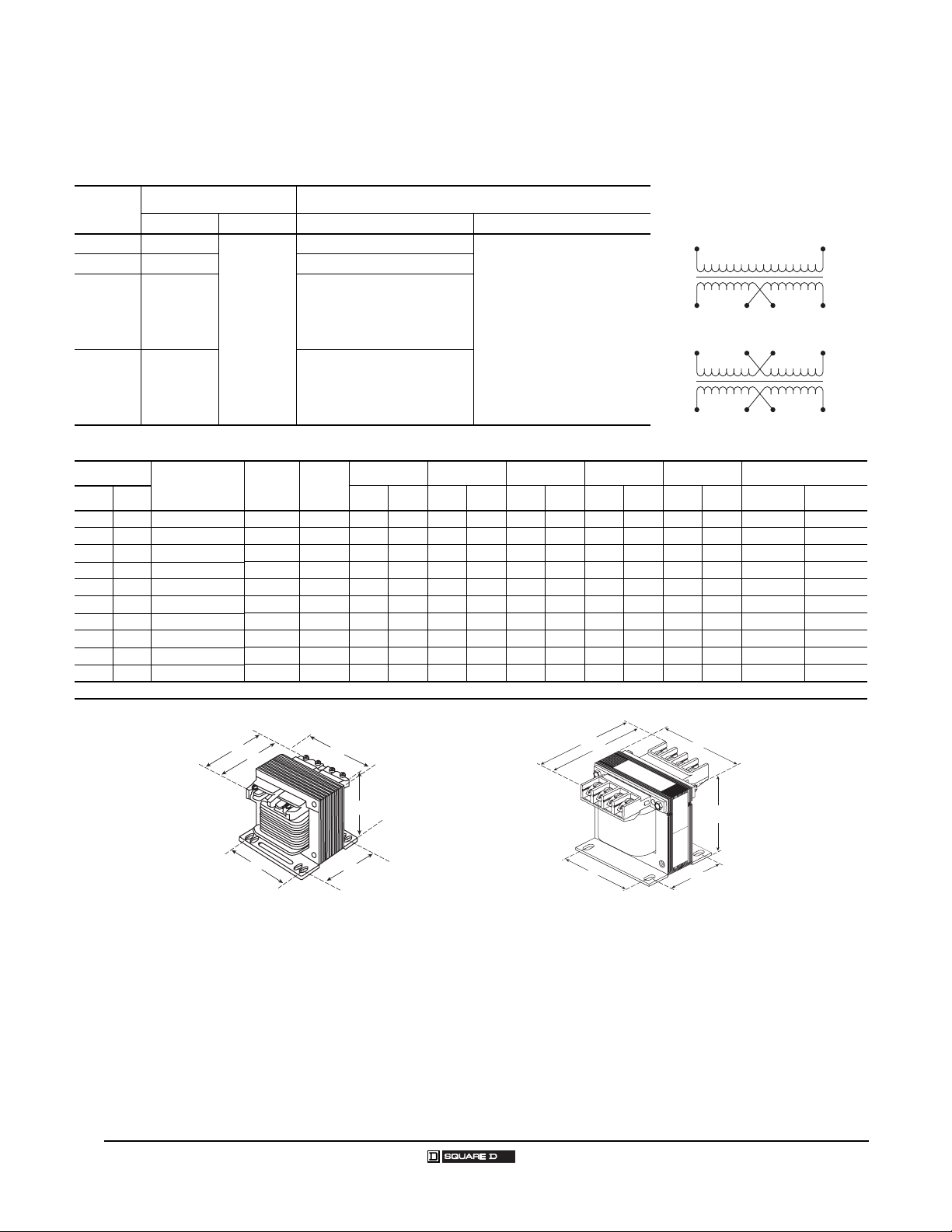
Voltages Connections
Primary Secondary Primary Secondary
220 x 440
230 x 460
240 x 480
110 x 220
115 x 230
120 x 240
Catalog
Number
110/220
115/230
120/240
110 x 220
115 x 230
120 x 240
1
Figure
220 or 230 or 240:Connect to H1 and H4
440 or 460 or 480:Connect to H1 and H4
110 or 115 or 120:Connect to H1 and H4
220 or 230 or 240:Connect to H1 and H4
Acc.
Key
Jumper H1 with H3
Jumper H2 with H4
Jumper H2 with H3
Jumper H1 with H3
Jumper H2 with H4
Jumper H2 with H3
ABCEF Slots
mm
IN
110 or 115 or 120:Connect to X1 and X4
220 or 230 or 240:Connect to X1 and X4
110 or 115 or 120:Connect to X1 and X4
220 or 230 or 240:Connect to X1 and X4
mm
IN
mm
Jumper X1 with X3
Jumper X2 with X4
Jumper X2 with X3
Jumper X1 with X3
Jumper X2 with X4
Jumper X2 with X3
IN
mm
IN
H3 H2
H1
X4 X2 X3
mm
IN
mm
H4
X1
08/2005
D
D
A
F
B
C
E
A
F
B
C
E
Figure 2Figure 1
© 1999–2005 Schneider Electric All Rights Reserved
13
Page 14
Industrial Control Transformers
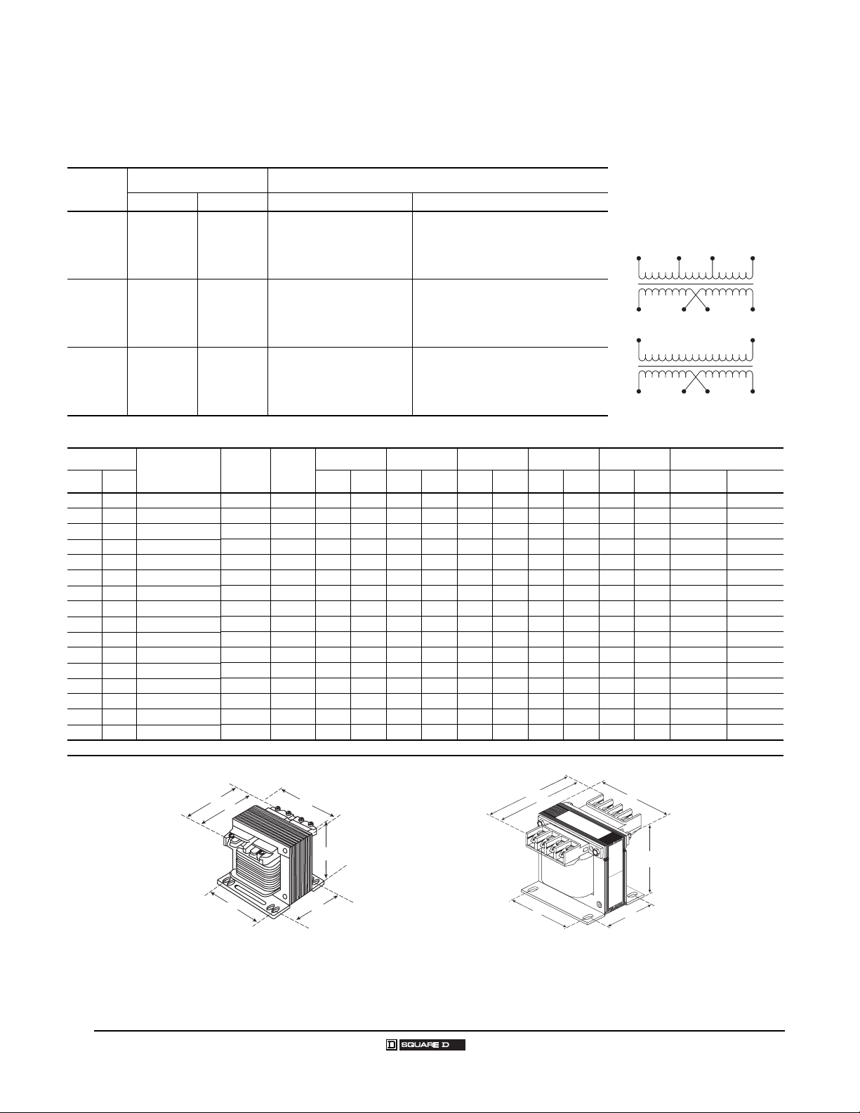
Type T Transformers with Dual Secondary
120/240 Volt Secondary
Voltage and Connection Options
Voltage
Code
D33 380/400/415 115/230
D37 550/575/600
D60 277 120/240 277: Connect to H1 and H2
Dimensions
VA
UL CE IN
25 25 9070T25t 1 I 3.09 79 3.00 76 2.58 66 2.00 51 2.50 64 0.20 x 0.38 5 x 10
50 50 9070T50t 1 I 3.09 79 3.00 76 2.58 66 2.00 51 2.50 64 0.20 x 0.38 5 x 10
75 75 9070T75t 1 I 3.34 85 3.38 86 2.89 73 2.38 61 2.81 71 0.20 x 0.48 5 x 12
100 100 9070T100t 1 I 3.34 85 3.38 86 2.89 73 2.38 61 2.81 71 0.20 x 0.48 5 x 12
150 150 9070T150t 1 I 3.59 91 3.75 95 3.20 81 2.88 73 3.13 80 0.20 x 0.38 5 x 10
200 200 9070T200t 1 I 3.59 91 3.75 95 3.20 81 2.88 73 3.13 80 0.20 x 0.38 5 x 10
250 160 9070T250t 2 I 5.30 135 3.75 95 3.21 82 2.88 73 3.13 80 0.20 x 0.38 5 x 10
300 200 9070T300t 2 I 4.74 120 4.50 114 3.84 98 2.56 65 3.75 95 0.20 x 0.38 5 x 10
350 250 9070T350t 2 I 5.11 130 4.50 114 3.84 98 3.00 76 3.75 95 0.20 x 0.38 5 x 10
500 300 9070T500t 2 I 5.49 139 4.50 114 3.84 98 3.56 90 3.75 95 0.20 x 0.38 5 x 10
750 500 9070T750t 2 I 5.61 143 5.25 133 4.51 115 3.43 87 4.38 111 0.28 x 0.56 7 x 14
1000 630 9070T1000t 2 I 6.30 160 5.25 133 4.51 115 4.31 109 4.38 111 0.28 x 0.56 7 x 14
1500 1000 9070T1500t 2 I 5.92 150 7.06 179 6.17 157 4.13 105 5.81 148 0.28 x 0.56 7 x 14
2000 1500 9070T2000t 2 I 7.17 182 7.06 179 6.17 157 4.56 116 5.81 148 0.28 x 0.56 7 x 14
3000 2000 9070T3000t 2 I 6.38 162 9.00 229 7.63 194 4.63 118 7.63 194 0.44 x 1.13 11 x 29
5000 3000 9070T5000t 2 I 8.31 211 9.00 229 7.63 194 6.56 167 7.63 194 0.44 x 1.13 11 x 29
1
Complete the catalog number by replacing the t with the correct Voltage Code from the “Voltage and Connection Options” table above.
Voltages Connections
Primary Secondary Primary Secondary
Catalog
Number
1
110/220
115/230
120/240
Figure
380: Connect to H1 and H2
400: Connect to H1 and H3
415: Connect to H1 and H4
550 or 575 or 600: Connect to
Acc.
Key
H1 and H2
ABCEF Slots
mm
115: Connect to X1 and X4
230: Connect to X1 and X4
110 or 115 or 120:Connect to X1 and X4
220 or 230 or 240:Connect to X1 and X4
120: Connect to X1 and X4
240: Connect to X1 and X4
IN
mm
Jumper X1 with X3
Jumper X2 with X4
Jumper X2 with X3
Jumper X1 with X3
Jumper X2 with X4
Jumper X2 with X3
Jumper X1 with X3
Jumper X2 with X4
Jumper X2 with X3
IN
mm
H1 H3 H4H2
X4 X2 X3 X1
H1
X4 X2 X3 X1
IN
mm
IN
mm
IN
H2
mm
D
D
A
F
B
C
E
A
F
B
C
E
Figure 2Figure 1
14
© 1999–2005 Schneider Electric All Rights Reserved 08/2005
Page 15
24 Volt Secondary
Voltage and Connection Options
Voltage
Code
D2 240 x 480 24
D23 120 x 240 24
D89 115 x 230 24
D92 230 x 460 24
Voltages Connections
Primary Secondary Primary Secondary
240: Connect to H1 and H4
Jumper H1 with H3
Jumper H2 with H4
480: Connect to H1 and H4
Jumper H2 with H3
120: Connect to H1 and H4
Jumper H1 with H3
Jumper H2 with H4
240: Connect to H1 and H4
Jumper H2 with H3
115: Connect to H1 and H4
Jumper H1 with H3
Jumper H2 with H4
230: Connect to H1 and H4
Jumper H2 with H3
230: Connect to H1 and H4
Jumper H1 with H3
Jumper H2 with H4
460: Connect to H1 and H4
Jumper H2 with H3
Industrial Control Transformers
Type T Transformers with 24 Volt Secondary
H1
Connect to X1 and X2
X2 X1
H2H3 H4
Dimensions
VA
UL CE IN
25 25 9070T25t 1 I 3.09 79 3.00 76 2.58 66 2.00 51 2.50 64 0.20 x 0.38 5 x 10
50 50 9070T50t 1 I 3.09 79 3.00 76 2.58 66 2.00 51 2.50 64 0.20 x 0.38 5 x 10
75 75 9070T75t 1 I 3.34 85 3.38 86 2.89 73 2.38 61 2.81 71 0.20 x 0.48 5 x 12
100 100 9070T100t 1 I 3.34 85 3.38 86 2.89 73 2.38 61 2.81 71 0.20 x 0.48 5 x 12
150 150 9070T150t 1 I 3.59 91 3.75 95 3.20 81 2.88 73 3.13 80 0.20 x 0.38 5 x 10
200 200 9070T200t 1 I 3.59 91 3.75 95 3.20 81 2.88 73 3.13 80 0.20 x 0.38 5 x 10
250 160 9070T250t 2 I 5.301353.75953.21822.88733.13800.20 x 0.385 x 10
300 200 9070T300t 2 I 4.74 120 4.50 114 3.84 98 2.56 65 3.75 95 0.20 x 0.38 5 x 10
350 250 9070T350t 2 I 5.11 130 4.50 114 3.84 98 3.00 76 3.75 95 0.20 x 0.38 5 x 10
500 300 9070T500t 2 I 5.49 139 4.50 114 3.84 98 3.56 90 3.75 95 0.20 x 0.38 5 x 10
1
Complete the catalog number by replacing the t with the correct Voltage Code from the “Voltage and Connection Options” table above.
Catalog
Number
Figure
1
D
A
F
Acc.
Key
B
ABCEF Slots
mm
IN
mm
IN
mm
IN
mm
IN
mm
D
A
C
E
F
B
C
E
IN
mm
Figure 2Figure 1
08/2005
© 1999–2005 Schneider Electric All Rights Reserved
15
Page 16
Industrial Control Transformers
Type T Transformers with 24 Volt Secondary
24 Volt Secondary
Voltage and Connection Options
Voltage
Code
D7 120 24
D14 208 24
D16 600 24
D25 277 24
D88 380 24
D112 230 24
Dimensions
VA
UL CE IN
25 25 9070T25t 1 I 3.09 79 3.00 76 2.58 66 2.00 51 2.50 64 0.20 x 0.38 5 x 10
50 50 9070T50t 1 I 3.09 79 3.00 76 2.58 66 2.00 51 2.50 64 0.20 x 0.38 5 x 10
75 75 9070T75t 1 I 3.34 85 3.38 86 2.89 73 2.38 61 2.81 71 0.20 x 0.48 5 x 12
100 100 9070T100t 1 I 3.34 85 3.38 86 2.89 73 2.38 61 2.81 71 0.20 x 0.48 5 x 12
150 150 9070T150t 1 I 3.59 91 3.75 95 3.20 81 2.88 73 3.13 80 0.20 x 0.38 5 x 10
200 200 9070T200t 1 I 3.59 91 3.75 95 3.20 81 2.88 73 3.13 80 0.20 x 0.38 5 x 10
250 160 9070T250t 2 I 5.30 135 3.75 95 3.21 82 2.88 73 3.13 80 0.20 x 0.38 5 x 10
300 200 9070T300t 2 I 4.74 120 4.50 114 3.84 98 2.56 65 3.75 95 0.20 x 0.38 5 x 10
350 250 9070T350t 2 I 5.11 130 4.50 114 3.84 98 3.00 76 3.75 95 0.20 x 0.38 5 x 10
500 300 9070T500t 2 I 5.49 139 4.50 114 3.84 98 3.56 90 3.75 95 0.20 x 0.38 5 x 10
1
Complete the catalog number by replacing the t with the correct Voltage Code from the “Voltage and Connection Options” table above.
Voltages Connections
Primary Secondary Primary Secondary
Connect to H1 and H2 Connect to X1 and X2
Catalog
Number
Fig.
1
Acc.
Key
ABCEF Slots
mm
IN
mm
IN
mm
H1
X2 X1
IN
mm
IN
mm
H2
IN
mm
D
D
A
F
B
C
E
A
F
B
C
E
Figure 2Figure 1
16
© 1999–2005 Schneider Electric All Rights Reserved 08/2005
Page 17
Industrial Control Transformers
Type T Transformers with 24 Volt Secondary
24 Volt Secondary
Voltage and Connection Options
Voltage
Code
D19
Dimensions
VA
UL CE IN
50 50 9070T50D19 4 III 4.43 113.0 3.38 85.9 2.89 73.4 2.38 61.0 2.81 71.4 0.20 x 0.48 5 x 12
75 75 9070T75D19 4 III 4.70 119.4 3.75 95.3 3.20 81.3 2.88 73.2 3.13 80.0 0.20 x 0.38 5 x 10
100 100 9070T100D19 4 III 4.70 119.4 3.75 95.3 3.20 81.3 2.88 73.2 3.13 80.0 0.20 x 0.38 5 x 10
150 150 9070T150D19 4 III 4.70 119.4 3.75 95.3 3.20 81.3 2.88 73.2 3.13 80.0 0.20 x 0.38 5 x 10
200 200 9070T200D19 4 III 4.74 120.4 4.50 114.3 3.84 98.0 2.56 65.0 3.75 95.3 0.20 x 0.38 5 x 10
250 160 9070T250D19 4 III 5.11 129.8 4.50 114.3 3.84 98.0 3.00 76.2 3.75 95.3 0.20 x 0.38 5 x 10
300 200 9070T300D19 4 III 5.11 129.8 4.50 114.3 3.84 98.0 3.00 76.2 3.75 95.3 0.20 x 0.38 5 x 10
350 250 9070T350D19 4 III 5.49 139.4 4.50 114.3 3.84 98.0 3.56 90.4 3.75 95.3 0.20 x 0.38 5 x 10
500 300 9070T500D19 4 III 5.61 142.5 5.25 133.4 4.51 114.6 3.43 87.1 4.38 111.3 0.28 x 0.56 7 x 14
Voltages Connections
Primary Secondary Primary Secondary
208
240
277
380
480
Catalog
Number
24
1
208: Connect to H1 and H2
240: Connect to H1 and H3
277: Connect to H1 and H4
380: Connect to H1 and H5
480: Connect to H1 and H6
Figure
Acc.
Key
Connect to X1 and X2
ABCEF Slots
mm
IN
mm
IN
mm
H1
X2 X1
IN
mm
IN
mm
H4 H6H5H2 H3
IN
mm
Figure 4
D
A
F
B
C
E
08/2005
© 1999–2005 Schneider Electric All Rights Reserved
17
Page 18
Industrial Control Transformers
Type T Transformers with 24 Volt Secondary
Type T Units with Dual 12/24 Volt Secondary
Voltage and Connection Options
Voltage
Code
D13 120
D36 600 Connect to H1 and H2
D54 120 x 240
D59 240 x 480
Dimensions
VA
UL CE IN
25 25 9070T25t 1 I 3.09 79 3.00 76 2.58 66 2.00 51 2.50 64 0.20 x 0.38 5 x 10
50 50 9070T50t 1 I 3.09 79 3.00 76 2.58 66 2.00 51 2.50 64 0.20 x 0.38 5 x 10
75 75 9070T75t 1 I 3.34 85 3.38 86 2.89 73 2.38 61 2.81 71 0.20 x 0.48 5 x 12
100 100 9070T100t 1 I 3.34 85 3.38 86 2.89 73 2.38 61 2.81 71 0.20 x 0.48 5 x 12
150 150 9070T150t 1 I 3.59 91 3.75 95 3.20 81 2.88 73 3.13 80 0.20 x 0.38 5 x 10
200 200 9070T200t 1 I 3.59 91 3.75 95 3.20 81 2.88 73 3.13 80 0.20 x 0.38 5 x 10
250 160 9070T250t 2 I 5.30 135 3.75 95 3.21 82 2.88 73 3.13 80 0.20 x 0.38 5 x 10
300 200 9070T300t 2 I 4.74 120 4.50 114 3.84 98 2.56 65 3.75 95 0.20 x 0.38 5 x 10
350 250 9070T350t 2 I 5.11 130 4.50 114 3.84 98 3.00 76 3.75 95 0.20 x 0.38 5 x 10
500 300 9070T500t 2 I 5.49 139 4.50 114 3.84 98 3.56 90 3.75 95 0.20 x 0.38 5 x 10
1
Complete the catalog number by replacing the t with the correct Voltage Code from the “Voltage and Connection Options” table above.
Voltages Connections
Primary Secondary Primary Secondary
Connect to H1 and H2
120: Connect to H1 and H4
Catalog
Number
Jumper H1 with H3
Jumper H2 with H4
12/24
Fig.
1
240: Connect to H1 and H4
Jumper H2 with H3
240: Connect to H1 and H4
Jumper H1 with H3
Jumper H2 with H4
480: Connect to H1 and H4
Jumper H2 with H3
Acc.
Key
ABCEF Slots
mm
IN
12: Connect to X1 and X4
Jumper X1 with X3
Jumper X2 with X4
24: Connect to X1 and X4
Jumper X2 with X3
mm
IN
mm
H1
X4 X2 X3 X1
H3 H2
H1
X4 X2 X3
IN
mm
IN
mm
H2
H4
X1
IN
mm
D
D
A
F
B
C
E
A
F
B
C
E
Figure 2Figure 1
18
© 1999–2005 Schneider Electric All Rights Reserved 08/2005
Page 19

Industrial Control Transformers
Multiple Secondary
MULTIPLE SECONDARY
Designed to meet the needs for both 24 V control and 120 V control. Available in the 9070 Type T
product line, with all the type T features.
Tapped Secondary D15: 24 V rated for 20% capacity and 120 V rated for 80% capacity when
simultaneous loading, or 100% loading when 120 V only.
20% rating at 24 V or 100% rating at 120 V gives equal output current from the device.
VA 24 V amps 120 V amps
50 .416 .416
75 .625 .625
100 .833 .833
150 1.25 1.25
200 1.67 1.67
250 2.08 2.08
300 2.5 2.5
350 2.9 2.9
500 4.17 4.17
750 6.25 6.25
1000 8.3 8.3
1500 12.5 12.5
2000 16.7 16.7
3000 25 25
5000 41.7 41.7
Tapped Secondary D65: Both outputs fully rated for non-simultaneous loading, and simultaneous rated
for any combination that does not exceed the nameplate VA rating.
Separate Windings Options: All voltage codes offer fully rated non-simultaneous loading, and
simultaneous rated for any combination that does not exceed the nameplate VA rating.
Features of separate windings:
1. Allows two isolated control circuits, 24 V and 120 V, from the same device
2. Wire sizing for circuits for each voltage not highest current for common when simultaneous loading.
(no common)
3. If a common is required, it can be obtained with a jumper kit.
08/2005
© 1999–2005 Schneider Electric All Rights Reserved
19
Page 20

Industrial Control Transformers
Multiple Secondary
Type T Units with Dual 24/120 Volt Secondary (Tapped Units)
Voltage and Connection Options
Voltage
Code
D15 240 x 480
Dimensions
VA
UL CE IN
50 50 9070T50D15 1 I 3.09 79 3.00 76 2.58 66 2.00 51 2.50 64 .20 x .38 5 x 10 50 10 40 10
75 75 9070T75D15 1 I 3.34 85 3.38 86 2.89 73 2.38 61 2.81 71 .20 x .48 5 x 12 75 15 60 10
100 100 9070T100D15 1 I 3.34 85 3.38 86 2.89 73 2.38 61 2.81 71 .20 x .48 5 x 12 100 20 80 20
150 150 9070T150D15 1 I 3.59 91 3.75 95 3.20 81 2.88 73 3.13 80 .20 x .38 5 x 10 150 30 120 30
200 200 9070T200D15 1 I 3.59 91 3.75 95 3.20 81 2.88 73 3.13 80 .20 x .38 5 x 10 200 40 160 40
250 160 9070T250D15 2 I 5.30 135 3.75 95 3.21 82 2.88 73 3.13 80 .20 x .38 5 x 10 250 50 200 50
300 200 9070T300D15 2 I 4.74 120 4.50 114 3.84 98 2.56 65 3.75 95 .20 x .38 5 x 10 300 60 240 60
350 250 9070T350D15 2 I 5.11 130 4.50 114 3.84 98 3.00 76 3.75 95 .20 x .38 5 x 10 350 70 280 70
500 300 9070T500D15 2 I 5.49 139 4.50 114 3.84 98 3.56 90 3.75 95 .20 x .38 5 x 10 500 100 400 100
750 500 9070T750D15 2 I 5.61 143 5.25 133 4.51 115 3.43 87 4.38 111 .28 x .56 7 x 14 750 150 600 150
1000 630 9070T1000D15 2 I 6.30 160 5.25 133 4.51 115 4.31 109 4.38 111 .28 x .56 7 x 14 1000 200 800 200
1500 1000 9070T1500D15 2 I 5.92 150 7.06 179 6.17 157 4.13 105 5.81 148 .28 x .56 7 x 14 1500 300 1200 300
2000 1500 9070T2000D15 2 I 7.17 182 7.06 179 6.17 157 4.56 116 5.81 148 .28 x .56 7 x 14 2000 400 1600 400
3000 2000 9070T3000D15 2 I 6.38 162 9.00 229 7.63 194 4.63 118 7.63 194
5000 3000 9070T5000D15 3 I 9.15 232 9.00 229 8.75 222 6.56 167 7.63 194
Voltages Connections
Primary Secondary Primary Secondary
240: Connect to H1 and H4
Jumper H1 with H3
Jumper H2 with H4
480: Connect to H1 and H4
Jumper H2 with H3
23 or 24 or 25: Connect to X1 and X2
110 or 115 or 120: Connect to X1 and X3
ABCEF Slots
mm
IN
mm
IN
mm
IN
mm
IN
mm
Catalog
Number
23/110
24/115
25/120
Fig.
Acc.
Key
IN
.44 x 1.13
.44 x 1.13
H3 H2
H1
X3 X2
120
24
Only
Only
Max
Max
VA
VA
mm
UL UL 120V 24V
11 x 29 3000 600 2400 600
11 x 29 5000 1000 4000 1000
H4
X1
Simultaneous
Loading Max
UL VA
D
D
A
F
B
C
E
A
F
Figure 2Figure 1
B
C
E
D
A
F
B
E
Figure 3
20
© 1999–2005 Schneider Electric All Rights Reserved 08/2005
C
Page 21

Industrial Control Transformers
Multiple Secondary
Type T Units with Dual 24/120 Volt Secondary (Tapped Units)
Voltage and Connection Options
Voltage
Code
D65
Dimensions
VA
UL CE IN
50 50 9070T50D65 1 II 3.34 85 3.38 86 2.89 73 2.38 61 2.81 71 .20 x .48 5 x 12 50 50
75 75 9070T75D65 1 II 3.59 91 3.75 95 3.20 81 2.88 73 3.13 80 .20 x .38 5 x 10 75 75
100 100 9070T100D65 1 II 3.59 91 3.75 95 3.20 81 2.88 73 3.13 80 .20 x .38 5 x 10 100 100
150 150 9070T150D65 1 II 3.59 91 3.75 95 3.20 81 2.88 73 3.13 80 .20 x .38 5 x 10 150 150
200 200 9070T200D65 2 II 5.11 130 4.50 114 3.84 98 3.00 76 3.75 95 .20 x .38 5 x 10 200 200
250 160 9070T250D65 2 II 5.11 130 4.50 114 3.84 98 3.00 76 3.75 95 .20 x .38 5 x 10 250 250
300 200 9070T300D65 2 II 5.49 139 4.50 114 3.84 98 3.56 90 3.75 95 .20 x .38 5 x 10 300 300
350 250 9070T350D65 2 II 5.61 143 5.25 133 4.51 115 3.43 87 4.38 111 .28 x .56 7 x 14 350 350
500 300 9070T500D65 2 II 5.61 143 5.25 133 4.51 115 3.43 87 4.38 111 .28 x .56 7 x 14 500 500
Voltages Connections
Primary Secondary Primary Secondary
200/220/440
208/230/460
217/240/480
Catalog
Number
23/110
24/115
25/120
Fig.
200 or 208 or 217:Connect to H1 and H2
220 or 230 or 240:Connect to H1 and H3
440 or 460 or 480:Connect to H1 and H4
Acc.
ABCEF Slots
Key
mm
IN
mm
23 or 24 or 25: Connect to X1 and X2
110 or 115 or 120:Connect to X1 and X3
IN
mm
IN
mm
IN
mm
H1 H3 H4H2
X3 X2 X1
115
Only
Max
VA
IN
mm
UL UL 115V 24V
24
Only
Max
VA
Simultaneous
Loading Max
UL VA
Any
combination
that does not
exceed
Primary Max
VA
For example,
T350
200VA (120V)
150VA (24V)
D
D
A
F
B
C
E
A
F
B
C
E
Figure 2Figure 1
08/2005
© 1999–2005 Schneider Electric All Rights Reserved
21
Page 22

Industrial Control Transformers
Multiple Secondary
Type T Units with Dual 24/120 Volt Secondary (Separate Windings)
Voltage and Connection Options
Voltage
Code
D114
Dimensions
VA
UL CE IN
50 50 9070T50D114 1 I 3.34 85 3.38 86 2.89 73 2.38 61 2.81 71 .20 x .48 5 x 12 50 50
75 75 9070T75D114 1 I 3.59 91 3.75 95 3.20 81 2.88 73 3.13 80 .20 x .38 5 x 10 75 75
100 100 9070T100D114 1 I 3.59 91 3.75 95 3.20 81 2.88 73 3.13 80 .20 x .38 5 x 10 100 100
150 150 9070T150D114 1 I 3.59 91 3.75 95 3.20 81 2.88 73 3.13 80 .20 x .38 5 x 10 150 150
200 200 9070T200D114 2 I 4.74 120 4.50 114 3.84 98 2.56 65 3.75 95 .20 x .38 5 x 10 200 200
250 160 9070T250D114 2 I 4.74 120 4.50 114 3.84 98 2.56 65 3.75 95 .20 x .38 5 x 10 250 250
300 200 9070T300D114 2 I 5.11 130 4.50 114 3.84 98 3.00 76 3.75 95 .20 x .38 5 x 10 300 300
350 250 9070T350D114 2 I 5.49 139 4.50 114 3.84 98 3.56 90 3.75 95 .20 x .38 5 x 10 350 350
500 300 9070T500D114 2 I 5.61 143 5.25 133 4.51 115 3.43 87 4.38 111 .28 x .56 7 x 14 500 500
Voltages Connections
Primary Secondary Primary Secondary
220 x 440
230 x 460
240 x 480
Catalog
Number
23/110
24/115
25/120
Fig.
220/230/240: Connect to H1 and H4
440/460/480: Connect to H1 and H4
Acc.
Key
Jumper H1 with H3
Jumper H2 with H4
Jumper H2 with H3
23/24/25: Connect to X1 and X2
110/115/120: Connect to X3 and X4
ABCEF Slots
mm
IN
mm
IN
mm
IN
mm
IN
mm
IN
H3 H2
H1
X4 X3 X2 X1
115
Only
Max
VA
mm
UL UL 115V 24V
24
Only
Max
VA
H4
Simultaneous
Loading Max
UL VA
Any
combination
that does not
exceed
Primary Max
VA
For example,
T350
200VA (120V)
150VA (24V)
D
D
A
F
B
C
E
A
F
B
C
E
Figure 2Figure 1
22
© 1999–2005 Schneider Electric All Rights Reserved 08/2005
Page 23

Type T Units with Dual 24/120 Volt Secondary (Separate Windings)
Industrial Control Transformers
Multiple Secondary
Voltage and Connection Options
Voltage
Code
D115 208/277 24/115
D116
D119 380/400/415 24/115
Voltages Connections
Primary Secondary Primary Secondary
550
575
600
23/110
24/115
25/120
208: Connect to H1 and H2
277: Connect to H1 and H3
Connect to H1 and H2
380: Connect to H1 and H2
400: Connect to H1 and H3
415: Connect to H1 and H4
24: Connect to X1 and X2
115: Connect to X3 and X4
23/24/25: Connect to X1 and X2
110/115/120: Connect to X3 and X4
24: Connect to X1 and X2
115: Connect to X3 and X4
H1 H2 H3
X4 X3 X2 X1
H1 H2
X4 X3 X2 X1
H1 H3 H4H2
X4 X3 X2 X1
Dimensions
115
VA
Catalog
Number
1
Key
Acc.
Fig.
UL CE IN
50 50 9070T50t 1 I 3.34 85 3.38 86 2.89 73 2.38 61 2.81 71 .20 x .48 5 x 12 50 50
75 75 9070T75t 1 I 3.59 91 3.75 95 3.20 81 2.88 73 3.13 80 .20 x .38 5 x 10 75 75
100 100 9070T100t 1 I 3.59 91 3.75 95 3.20 81 2.88 73 3.13 80 .20 x .38 5 x 10 100 100
150 150 9070T150t 1 I 3.59 91 3.75 95 3.20 81 2.88 73 3.13 80 .20 x .38 5 x 10 150 150
200 200 9070T200t 2 I 4.74 120 4.50 114 3.84 98 2.56 65 3.75 95 .20 x .38 5 x 10 200 200
250 160 9070T250t 2 I 4.74 120 4.50 114 3.84 98 2.56 65 3.75 95 .20 x .38 5 x 10 250 250
300 200 9070T300t 2 I 5.11 130 4.50 114 3.84 98 3.00 76 3.75 95 .20 x .38 5 x 10 300 300
350 250 9070T350t 2 I 5.49 139 4.50 114 3.84 98 3.56 90 3.75 95 .20 x .38 5 x 10 350 350
500 300 9070T500t 2 I 5.61 143 5.25 133 4.51 115 3.43 87 4.38 111 .28 x .56 7 x 14 500 500
1
Complete the catalog number by replacing the t with the correct Voltage Code from the “Voltage and Connection Options” table above.
ABCEF Slots
mm
IN
mm
IN
mm
IN
mm
IN
mm
IN
Only
Max
VA
mm
UL UL 115V 24V
24
Only
Max
VA
Simultaneous
Loading Max
UL VA
Any
combination
that does not
exceed
Primary Max
VA
For example,
T350
200VA (120V)
150VA (24V)
08/2005
D
D
A
F
B
C
E
A
F
B
C
E
Figure 2Figure 1
© 1999–2005 Schneider Electric All Rights Reserved
23
Page 24

Industrial Control Transformers
Multiple Secondary
Type T Units with Dual 24/120 Volt Secondary (Separate Windings)
Voltage and Connection Options
Voltage
Code
D117
D118
Dimensions
VA
UL CE IN
50 50 9070T50t 1 II 3.34853.38862.89732.38612.8171.20 x .485 x 12 50 50
75 75 9070T75t 1 II 3.59913.75953.20812.88733.1380.20 x .385 x 10 75 75
100 100 9070T100t 1 II 3.59913.75953.20812.88733.1380.20 x .385 x 10 100 100
150 150 9070T150t 1 II 3.59913.75953.20812.88733.1380.20 x .385 x 10 150 150
200 200 9070T200t 2 II 4.74 120 4.50 114 3.84 98 2.56 65 3.75 95 .20 x .38 5 x 10 200 200
250 160 9070T250t 2 II 4.74 120 4.50 114 3.84 98 2.56 65 3.75 95 .20 x .38 5 x 10 250 250
300 200 9070T300t 2 II 5.11 130 4.50 114 3.84 98 3.00 76 3.75 95 .20 x .38 5 x 10 300 300
350 250 9070T350t 2 II 5.49 139 4.50 114 3.84 98 3.56 90 3.75 95 .20 x .38 5 x 10 350 350
500 300 9070T500t 2 II 5.61 143 5.25 133 4.51 115 3.43 87 4.38 111 .28 x .56 7 x 14 500 500
1
Complete the catalog number by replacing the t with the correct Voltage Code from the “Voltage and Connection Options” table above.
Voltages Connections
Primary Secondary Primary Secondary
200/220/400
208/230/460
217/240/480
220/440/550
230/460/575
240/480/600
Catalog
Number
23/110
24/115
25/120
23/110
24/115
25/120
Fig.
1
200/208/217: Connect to H1 and H2
220/230/240: Connect to H1 and H3
400/460/480: Connect to H1 and H4
220/230/240: Connect to H1 and H2
440/460/480: Connect to H1 and H3
550/575/600: Connect to H1 and H4
Acc.
ABCEF Slots
Key
mm
IN
mm
23/24/25: Connect to X1 and X2
110/115/120: Connect to X3 and X4
IN
mm
IN
mm
IN
mm
IN
H1 H3 H4H2
X4 X3 X2 X1
115
Only
Only
Max
Max
VA
mm
UL UL 115V 24V
24
VA
Simultaneous
Loading Max
UL VA
Any
combination
that does not
exceed
Primary Max
VA
For example,
T350
200VA (120V)
150VA (24V)
D
D
A
F
B
C
E
A
F
B
C
E
Figure 2Figure 1
24
© 1999–2005 Schneider Electric All Rights Reserved 08/2005
Page 25

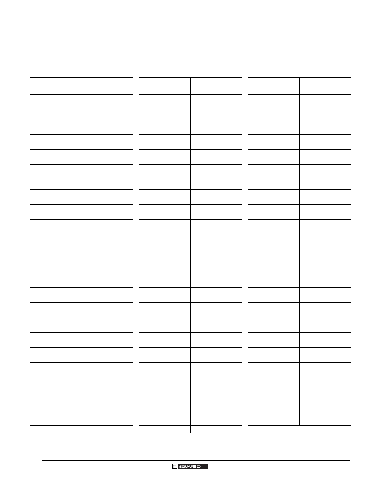
TYPE T PERFORMANCE DATA
Industrial Control Transformers
Type T Transformers
Catalog
Number
9070T25D1 4.5 3.7 8.2 3.81 75.3 3.84 10.9 28 22 19 16 15 25.0 30.0
9070T50D1 4.5 7.1 11.6 7.97 81.1 8.01 10.5 40 29 21 17 15 24.1 28.9
9070T75D1 7.3 6.8 14.1 4.94 84.2 5.00 15.9 48 38 31 26 25 28.0 33.6
9070T100D1 7.3 10.2 17.5 6.82 85.1 6.9 15.4 60 45 34 27 25 26.8 32.2
9070T150D1 10.5 10.8 21.3 4.77 87.6 5.25 20.2 73 57 45 38 36 31.2 37.4
9070T200D1 10.5 19.5 30.0 7.70 86.9 7.83 18.0 102 73 53 40 36 19.7 23.7
9070T250D1 14.1 17.8 31.9 5.73 88.7 5.73 3.5 109 82 63 52 48 22.9 27.5
9070T300D1 13.3 18.8 32.1 5.60 90.3 5.62 6.0 110 82 61 49 45 11.0 13.2
9070T350D1 16.4 19.9 36.3 5.07 90.6 5.08 4.9 124 94 73 60 56 16.0 19.2
9070T500D1 20.7 30.6 51.3 5.47 90.7 5.48 5.3 175 129 97 77 71 12.9 15.5
9070T750D1 30.8 37.9 68.7 4.57 91.6 4.58 5.7 235 178 138 113 105 17.4 20.9
9070T1000D1 35.4 51.3 86.7 4.83 92.0 4.84 6.0 296 219 165 132 121 10.3 12.3
9070T1500D1 51.5 51.3 102.8 3.25 93.6 3.30 8.0 351 274 220 187 176 10.5 12.6
9070T2000D1 81.8 50.0 131.8 2.31 93.8 2.31 6.3 450 375 322 290 279 15.6 18.8
9070T3000D1 81.9 67.2 149.1 2.24 96.1 2.04 9.3 532 415 338 294 285 7.7 9.3
9070T5000D1 143.3 83.7 227.0 1.67 95.6 1.52 7.2 781 648 558 507 495 8.5 10.2
9070T50D3 4.5 7.1 11.6 7.97 81.1 8.01 10.5 40 29 21 17 15 24.1 28.9
9070T75D3 7.3 6.8 14.1 4.94 84.2 5.00 15.9 48 38 31 26 25 28.0 33.6
9070T100D3 7.3 10.2 17.5 6.82 85.1 6.90 15.4 60 45 34 27 25 26.8 32.2
9070T150D3 10.5 10.8 21.3 4.77 87.6 5.25 20.2 73 57 45 38 36 31.2 37.4
9070T200D3 10.5 19.5 30.0 7.70 86.9 7.83 18.0 102 73 53 40 36 19.7 23.7
9070T250D3 14.1 17.8 31.9 5.73 88.7 5.73 3.5 109 82 63 52 48 22.9 27.5
9070T300D3 13.3 18.8 32.1 5.60 90.3 5.62 6.0 110 82 61 49 45 11.0 13.2
9070T350D3 16.4 19.9 36.3 5.07 90.6 5.08 4.9 124 94 73 60 56 16.0 19.2
9070T500D3 20.7 30.6 51.3 5.47 90.7 5.48 5.3 175 129 97 77 71 12.9 15.5
9070T750D3 30.8 37.9 68.7 4.57 91.6 4.58 5.7 235 178 138 113 105 17.4 20.9
9070T1000D3 35.4 51.3 86.7 4.83 92.0 4.84 6.0 296 219 165 132 121 10.3 12.3
9070T1500D3 51.5 51.3 102.8 3.25 93.6 3.30 8.0 351 274 220 187 176 10.5 12.6
9070T2000D3 81.8 50.0 131.8 2.31 93.8 2.31 6.3 450 375 322 290 279 15.6 18.8
9070T3000D3 81.9 74.5 156.4 2.37 95 2.39 11.9 534 423 343 296 280 7.7 9.3
9070T5000D3
Core
Watts
Coil
Watts
FL Total
Watts
Reg
1.0PF
Eff
100%
%IZ X/R
100% 75% 50% 25%
No
Load
60HZ 50HZ
BTU/hr Inrush (x FL RMS)
9070T50D20 7.3 6.8 14.1 4.94 84.2 5.00 15.9 48 38 31 26 25 28.0 33.6
9070T75D20 7.3 10.2 17.5 6.82 85.1 6.90 15.4 60 45 34 27 25 26.8 32.2
9070T100D20 10.5 10.8 21.3 4.77 87.6 5.25 20.2 73 57 45 38 36 31.2 37.4
9070T150D20 10.5 19.5 30.0 7.70 86.9 7.83 18.0 102 73 53 40 36 19.7 23.7
9070T200D20 14.1 17.8 31.9 5.73 88.7 5.73 3.5 109 82 63 52 48 22.9 27.5
9070T250D20 13.3 18.8 32.1 5.60 90.3 5.62 6.0 110 82 61 49 45 11.0 13.2
9070T300D20 16.4 19.9 36.3 5.07 90.6 5.08 4.9 124 94 73 60 56 16.0 19.2
9070T350D20 20.7 30.6 51.3 5.47 90.7 5.48 5.3 175 129 97 77 71 12.9 15.5
9070T500D20 30.8 37.9 68.7 4.57 91.6 4.58 5.7 235 178 138 113 105 17.4 20.9
9070T750D20 35.4 51.3 86.7 4.83 92.0 4.84 6.0 296 219 165 132 121 10.3 12.3
9070T1000D20 51.5 51.3 102.8 3.25 93.6 3.30 8.0 351 274 220 187 176 10.5 12.6
9070T1500D20 81.8 50.0 131.8 2.31 93.8 2.31 6.3 450 375 322 290 279 15.6 18.8
9070T2000D20 81.9 74.5 156.4 2.37 95.0 2.39 11.9 534 423 343 296 280 7.7 9.3
9070T3000D20 143.3 84.8 228.1 1.63 95.6 1.64 11.8 779 652 562 507 489 8.5 10.2
08/2005
© 1999–2005 Schneider Electric All Rights Reserved
25
Page 26

Industrial Control Transformers
Type T Transformers
TYPE T - SPECIAL QUOTE REQUEST SHEET
Determine VA by Load Requirements
Dual or CT Secondary
Secondary Voltages: ____ x ____ or ____ CT
Amps at higher of the two voltages ________
Tapped Unit Separate Windings
Secondary 1: ______ Volts ______ Amps Secondary 1: ______ Volts ______ Amps
Secondary 2: ______ Volts ______ Amps Secondary 2: ______ Volts ______ Amps
Secondary 3: ______ Volts ______ Amps Secondary 3: ______ Volts ______ Amps
Secondary 4: ______ Volts ______ Amps
Secondary 5: ______ Volts ______ Amps
Secondary Simultaneous Loading?
If Yes: VA Sizing ______
S1: V x A + S2: V x A + S3: V x A + S4: V x A + S5: V x A
If No: VA Sizing ______
Largest VA of the secondary listed above: V x A
Dual Primary _____ x _____ Volts
Tapped Unit
Primary 1: _____ Volts
Primary 2: _____ Volts
Primary 3: _____ Volts
Primary 4: _____ Volts
Primary 5: _____ Volts
Technical Data
Regulation Requirements: ______ VA @ ______ PF for ______% Voltage Drop
BTU Requirements: ______ No Load Max ______ Total Full Load Max
Dimensions
If dimensions are critical, provide them below (or supply a drawing with dimensions clearly marked):
Maximum size in inches: _____ H ____ W _____ D
All units will have standard Type T features:
Temperature Rise, Insulation Material, Terminal Board, cULus and CE Marked,
Footprints for VA frame created above.
26
© 1999–2005 Schneider Electric All Rights Reserved 08/2005
Page 27

Industrial Control Transformers
TYPE EO TRANSFORMERS
Type EO Transformers
Type EO VA Ratings
Type
60 Hz 50 Hz
EO17 25 25
EO1 50 35
EO18 75 75
EO2 100
EO3 150 120
EO19 200 200
EO15 250 200
EO4 300 240
EO16 350 280
EO51 500 400
EO61 750 500
EO71 1000 900
EO81 1500 1300
EO91 2000 1800
EO10 3000 3000
EO11 5000 5000
Example:
This example assumes the following:
• Two NEMA size 0 contactors do not start together, but one
could be ON when the other starts.
• One NEMA size 2 contactor can start with either of the
other contactors.
• One pilot light at 2 VA
1. VA and inrush are:
NEMA 0: sealed 27 VA; inrush 245 VA
NEMA 2: sealed 37 VA; inrush 311 VA; pilot light 2 VA
2. Total VA: 27 + 27 + 37 + 2 = 93 VA
3. Total inrush VA: 245 + 311 + 27 + 2 = 582 VA
4. From Regulation Chart for Type EO at right below:
100 VA minimum unit; inrush 606 VA will not work at 90%
150 VA (next standard size); inrush 755 VA will work at 95%
VA
70
The Type EO units are designed with exceptional voltage regulation. These
control transformers are constructed using traditional materials and
manufacturing techniques, and are designed for 25 VA to 5000 VA with a
55° C temperature rise. When exceptional regulation and very low
temperature rise are an absolute necessity, choose the Type EO units.
Type EO Listings
Listing File VA Range
UL E61239 25–5000
CSA LR37055, Guide 184-N-90 25–5000
Selection Guide
1. Determine inrush and sealed VA of each coil in the control circuit and VA
of all other components.
2. Total all sealed VA of all operating coils and other loads VA (determines
minimal VA size required for the circuit).
3. Total the inrush VA of all coils that are starting at the same time and all
loads and coils that are running (using the regulation chart to give
possible units to be used).
4. Take VA size from step 2, go to standard VA size in chart below. Make
sure inrush VA from chart is greater than total VA from step 3. If not, go
to next larger VA size and repeat.
If your supply voltage is stable and fluctuates less than 5%, we recommend
you use the 90% secondary voltage column. If your supply voltage is not
stable and fluctuates more than 10%, we recommend you use the 95%
secondary voltage column. We recommend that you never use the 85%
secondary voltage column since magnetic devices lose life expectancy if
they are continuously started at 85% of rated voltage.
Regulation Chart for Type EO
Secondary Voltage
VA
Inrush UL VA at 20% Power Factor Inrush UL VA at 40% Power Factor
95% 90% 85% 95% 90% 85%
25 95 ... 146 60 ... 119
50 164 213 277 123 168 225
75 387 487 622 284 375 798
100 479 606 770 346 463 613
150 755 1177 1532 567 930 1252
200 1260 1883 2419 910 1462 1950
250 1530 2327 2995 1115 1811 2419
300 2030 2981 3800 1455 2290 3038
350 2920 4586 5981 2180 3637 4903
500 4230 5984 7707 3120 4661 6229
750 7430 11460 14736 5380 8907 11891
1000 10300 16873 21734 7450 13145 17571
1500 19200 30042 39217 14500 23859 32179
2000 27750 45194 60022 21750 36901 50994
3000 31800 82333 108205 26750 66072 89509
5000 86100 148768 202077 72600 126887 175552
08/2005
© 1999–2005 Schneider Electric All Rights Reserved
27
Page 28

Industrial Control Transformers
Type EO Transformers
Use the following tables to quickly find a Type EO transformer for your specific application. First, find
your source and load voltages in either the 120 or 24 Volt table below. Then, go to the indicated pages
for details on the transformer(s) matching those voltages.
Type EO Transformers for 120 Volt Loads
Source
Voltage
110 110 D24 30
115 115 D24 30
120 120 D24 30
200 115 D93 30
208 120 D3 30
220 110 D1 29
230 115 D1 29
240 120 D1 29
277 120 D4 30
380 110 D6 30
400 120 D103 30
415 110 D17 30
440 110 D1 29
460 115 D1 29
480 120 D1 29
550 110 D5 30
575 115 D5 30
600 120 D5 30
Load
Voltage
Voltage
Code(s)
Go To
Page(s)
Type EO Transformers for 24 Volt Loads
Source
Voltage
115 24 D89 31
120 24 D23, D7 31, 32
208 24 D14 20
230 24 D89, D112 31, 32
240 24 D2, D23 31, 31
277 24 D25 32
380 24 D88 32
460 24 D92 31
480 24 D2 31
600 24 D16 32
Load
Voltage
Voltage
Code(s)
Go To
Page(s)
28
© 1999–2005 Schneider Electric All Rights Reserved 08/2005
Page 29

Industrial Control Transformers
Type EO Transformers
120 Volt Control Secondary
Voltage and Connection Options
Voltage
Code
D1
1
Jumper kit (two jumpers) supplied with unit.
Dimensions
VA
25 9070EO17D1 6 3.31 84 3.00 76 2.50 64 1.75 44 2.50 64 0.20 x 0.38 5 x 10
50 9070EO1D1 6 3.31 84 3.00 76 2.50 64 2.00 51 2.50 64 0.20 x 0.38 5 x 10
75 9070EO18D1 6 3.78 96 3.38 86 2.81 71 2.19 56 2.81 71 0.20 x 0.38 5 x 10
100 9070EO2D1 6 3.78 96 3.38 86 2.81 71 2.38 60 2.81 71 0.20 x 0.38 5 x 10
150 9070EO3D1 6 4.44 113 3.75 95 3.13 80 2.88 73 3.13 80 0.20 x 0.38 5 x 10
200 9070EO19D1 6 4.81 122 4.50 114 3.75 95 2.5 63 3.75 95 0.20 x 0.38 5 x 10
250 9070EO15D1 6 5.19 132 4.50 114 3.75 95 2.88 73 3.75 95 0.20 x 0.38 5 x 10
300 9070EO04D1 6 5.56 141 4.50 114 3.75 95 3.81 97 3.75 95 0.20 x 0.38 5 x 10
350 9070EO16D1 6 6.19 157 4.50 114 3.75 95 3.81 97 3.75 95 0.20 x 0.38 5 x 10
500 9070EO51D1 6 6.56 167 5.25 133 4.38 111 3.81 97 4.38 111 0.28 x 0.56 7 x 14
750 9070EO61D1 6 7.94 202 5.25 133 4.38 111 5.13 130 4.38 111 0.28 x 0.56 7 x 14
1000 9070EO71D1 6 7.94 202 6.00 152 5.00 127 4.75 121 5.00 127 0.28 x 0.56 7 x 14
1500 9070EO81D1 6 8.59 218 7.06 179 6.03 153 5.88 149 5.81 148 0.44 x 0.69 11 x 18
2000 9070EO91D1 6 9.22 234 7.06 179 6.03 153 6.50 165 5.81 148 0.44 x 0.69 11 x 18
3000 9070EO10D1 6 9.44 239 9.00 229 7.50 191 5.88 149 7.63 194 0.44 x 0.69 11 x 18
5000 9070EO11D1 6 12.06 306 9.00 229 7.50 191 8.50 216 7.63 194 0.44 x 0.69 11 x 18
Number
Voltages Connections
Primary Secondary Primary Secondary
220 x 440
230 x 460
240 x 480
Catalog
110
115
120
Figure
220/230/240: Connect to H1 and H4
440/460/480: Connect to H1 and H4
ABCEF Slots
IN
Jumper H1 with H3
Jumper H2 with H4
Jumper H2 with H3
mm
IN
mm
Connect to X1 and X2
1
IN
mm
H1
X2 X1
IN
mm
IN
mm
IN
H2H3 H4
mm
08/2005
Figure 6
29
© 1999–2005 Schneider Electric All Rights Reserved
Page 30

Industrial Control Transformers
Type EO Transformers
120 Volt Control Secondary
Voltage and Connection Options
Voltage
Code
D3 208 120
D4 277 120
D5
D6 380 110
D17 415 110
D24
D93 200 115
D103 400 120
Dimensions
VA
25 9070EO17t 6 3.31 84 3.00 76 2.50 64 1.75 44 2.50 64 0.20 x 0.38 5 x 10
50 9070EO1t 6 3.31 84 3.00 76 2.50 64 2.00 51 2.50 64 0.20 x 0.38 5 x 10
75 9070EO18t 6 3.78 96 3.38 86 2.81 71 2.19 56 2.81 71 0.20 x 0.38 5 x 10
100 9070EO2t 6 3.78 96 3.38 86 2.81 71 2.38 60 2.81 71 0.20 x 0.38 5 x 10
150 9070EO3t 6 4.44 113 3.75 95 3.13 80 2.88 73 3.13 80 0.20 x 0.38 5 x 10
200 9070EO19t 6 4.81 122 4.50 114 3.75 95 2.5 63 3.75 95 0.20 x 0.38 5 x 10
250 9070EO15t 6 5.19 132 4.50 114 3.75 95 2.88 73 3.75 95 0.20 x 0.38 5 x 10
300 9070EO04t 6 5.56 141 4.50 114 3.75 95 3.81 97 3.75 95 0.20 x 0.38 5 x 10
350 9070EO16t 6 6.19 157 4.50 114 3.75 95 3.81 97 3.75 95 0.20 x 0.38 5 x 10
500 9070EO51t 6 6.56 167 5.25 133 4.38 111 3.81 97 4.38 111 0.28 x 0.56 7 x 14
750 9070EO61t 6 7.94 202 5.25 133 4.38 111 5.13 130 4.38 111 0.28 x 0.56 7 x 14
1000 9070EO71t 6 7.94 202 6.00 152 5.00 127 4.75 121 5.00 127 0.28 x 0.56 7 x 14
1500 9070EO81t 6 8.59 218 7.06 179 6.03 153 5.88 149 5.81 148 0.44 x 0.69 11 x 18
2000 9070EO91t 6 9.22 234 7.06 179 6.03 153 6.50 165 5.81 148 0.44 x 0.69 11 x 18
3000 9070EO10t 6 9.44 239 9.00 229 7.50 191 5.88 149 7.63 194 0.44 x 0.69 11 x 18
5000 9070EO11t 6 12.06 306 9.00 229 7.50 191 8.50 216 7.63 194 0.44 x 0.69 11 x 18
1
Complete the catalog number by replacing the t with the correct Voltage Code from the “Voltage and Connection Options” table above.
Number
Voltages Connections
Primary Secondary Primary Secondary
550
575
600
110
115
120
Catalog
1
110
115
120
110
115
120
Figure
Connect to H1 and H2 Connect to X1 and X2
ABCEF Slots
mm
IN
IN
mm
IN
mm
H1
X2 X1
IN
mm
IN
mm
IN
H2
mm
Figure 6
30
© 1999–2005 Schneider Electric All Rights Reserved 08/2005
Page 31

Industrial Control Transformers
Type EO Transformers
24 Volt Control Secondary
Voltage and Connection Options
Voltage
Code
D2 240 x 480
D23 120 x 240
D89 115 x 230
D92 230 x 460
Dimensions
VA
25 9070EO17t 6 3.31 84 3.00 76 2.50 64 1.75 44 2.50 64 0.20 x 0.38 5 x 10
50 9070EO1t 6 3.31 84 3.00 76 2.50 64 2.00 51 2.50 64 0.20 x 0.38 5 x 10
75 9070EO18t 6 3.78 96 3.38 86 2.81 71 2.19 56 2.81 71 0.20 x 0.38 5 x 10
100 9070EO2t 6 3.78 96 3.38 86 2.81 71 2.38 60 2.81 71 0.20 x 0.38 5 x 10
150 9070EO3t 6 4.44 113 3.75 95 3.13 80 2.88 73 3.13 80 0.20 x 0.38 5 x 10
200 9070EO19t 6 4.81 122 4.50 114 3.75 95 2.5 63 3.75 95 0.20 x 0.38 5 x 10
250 9070EO15t 6 5.19 132 4.50 114 3.75 95 2.88 73 3.75 95 0.20 x 0.38 5 x 10
300 9070EO04t 6 5.56 141 4.50 114 3.75 95 3.81 97 3.75 95 0.20 x 0.38 5 x 10
350 9070EO16t 6 6.19 157 4.50 114 3.75 95 3.81 97 3.75 95 0.20 x 0.38 5 x 10
500 9070EO51t 6 6.56 167 5.25 133 4.38 111 3.81 97 4.38 111 0.28 x 0.56 7 x 14
750 9070EO61t 6 7.94 202 5.25 133 4.38 111 5.13 130 4.38 111 0.28 x 0.56 7 x 14
1000 9070EO71t 6 7.94 202 6.00 152 5.00 127 4.75 121 5.00 127 0.28 x 0.56 7 x 14
1500 9070EO81t 6 8.59 218 7.06 179 6.03 153 5.88 149 5.81 148 0.44 x 0.69 11 x 18
1
Complete the catalog number by replacing the t with the correct Voltage Code from the “Voltage and Connection Options” table above.
Number
Voltages Connections
Primary Secondary Primary Secondary
Catalog
240 or 120 or 115 or 230:Connect to H1 and H4
24
480 or 240 or 230 or 460:Connect to H1 and H4
ABCEF Slots
1
Fig.
mm
IN
Jumper H1 with H3
Jumper H2 with H4
Jumper H2 with H3
IN
mm
Connect to X1 and X2
IN
mm
IN
mm
H1
X2 X1
IN
mm
IN
H2H3 H4
mm
08/2005
Figure 6
31
© 1999–2005 Schneider Electric All Rights Reserved
Page 32

Industrial Control Transformers
Type EO Transformers
24 Volt Control Secondary
Voltage and Connection Options
Voltage
Code
D7 120
D14 208
D16 600
D25 277
D88 380
D112 230
Dimensions
VA
25 9070EO17t 6 3.31 84 3.00 76 2.50 64 1.75 44 2.50 64 0.20 x 0.38 5 x 10
50 9070EO1t 6 3.31 84 3.00 76 2.50 64 2.00 51 2.50 64 0.20 x 0.38 5 x 10
75 9070EO18t 6 3.78963.38 862.81712.19562.81 710.20 x 0.38 5 x 10
100 9070EO2t 6 3.78963.38 862.81712.38602.81 710.20 x 0.38 5 x 10
150 9070EO3t 6 4.44 113 3.75 95 3.13 80 2.88 73 3.13 80 0.20 x 0.38 5 x 10
200 9070EO19t 6 4.81 122 4.50 114 3.75 95 2.5 63 3.75 95 0.20 x 0.38 5 x 10
250 9070EO15t 6 5.19 132 4.50 114 3.75 95 2.88 73 3.75 95 0.20 x 0.38 5 x 10
300 9070EO04t 6 5.56 141 4.50 114 3.75 95 3.81 97 3.75 95 0.20 x 0.38 5 x 10
350 9070EO16t 6 6.19 157 4.50 114 3.75 95 3.81 97 3.75 95 0.20 x 0.38 5 x 10
500 9070EO51t 6 6.56 167 5.25 133 4.38 111 3.81 97 4.38 111 0.28 x 0.56 7 x 14
750 9070EO61t 6 7.94 202 5.25 133 4.38 111 5.13 130 4.38 111 0.28 x 0.56 7 x 14
1000 9070EO71t 6 7.94 202 6.00 152 5.00 127 4.75 121 5.00 127 0.28 x 0.56 7 x 14
1500 9070EO81t 6 8.59 218 7.06 179 6.03 153 5.88 149 5.81 148 0.44 x 0.69 11 x 18
1
Complete the catalog number by replacing the t with the correct Voltage Code from the “Voltage and Connection Options” table above.
Number
Voltages Connections
Primary Secondary Primary Secondary
24 Connect to H1 and H2 Connect to X1 and X2
Catalog
1
Fig.
ABCEF Slots
IN
mm
IN
mm
IN
mm
H1
X2 X1
IN
mm
IN
mm
IN
H2
mm
Figure 6
32
© 1999–2005 Schneider Electric All Rights Reserved 08/2005
Page 33

TYPE EO PERFORMANCE DATA
Industrial Control Transformers
Type EO Transformers
Catalog
Number
9070EO17D1 2.25 2.25 4.50 6.37% 84.75% 7.38 0.151 15.35 10.84 9.16 8.32 7.68 44.70
9070EO1D1 3.50 4.20 7.70 7.35% 86.66% 7.69 0.158 26.27 20.66 16.20 13.19 11.94 44.70
9070EO18D1 4.25 4.85 9.10 5.63% 89.18% 5.62 0.079 31.05 25.45 20.79 17.45 14.50 32.30
9070EO2D1 4.91 7.29 12.20 6.53% 89.13% 6.21 0.056 41.63 30.86 24.07 20.59 16.75 26.50
9070EO3D1 8.53 6.77 15.30 4.40% 90.74% 4.16 0.173 52.20 43.02 36.73 32.53 29.10 52.60
9070EO19D1 8.38 8.52 16.90 4.04% 92.21% 3.72 0.111 57.66 46.69 38.68 33.48 28.59 40.60
9070EO15D1 9.83 10.37 20.20 4.10% 92.52% 3.73 0.119 68.92 55.46 45.77 39.58 33.54 39.00
9070EO4D1 6.50 10.00 16.50 3.75% 94.79% 3.61 0.075 56.30 43.20 31.47 24.85 22.18 51.10
9070EO16D1 17.75 8.85 26.60 2.85% 92.94% 2.44 0.188 90.76 80.23 69.07 62.61 60.56 59.70
9070EO51D1 17.51 14.69 32.20 2.91% 93.95% 2.72 0.13 109.87 87.55 69.97 61.54 59.74 37.20
9070EO61D1 23.67 19.53 43.20 2.72% 94.55% 2.31 0.113 147.40 114.30 91.41 83.37 80.76 43.40
9070EO71D1 18.12 15.78 33.90 2.01% 96.72% 2.02 0.125 115.67 98.130 77.00 64.93 61.83 57.10
9070EO81D1 38.51 24.89 63.40 1.66% 95.94% 1.63 0.188 216.32 180.18 153.47 138.03 131.40 37.50
9070EO91D1 53.09 30.01 83.10 1.50% 96.01% 1.25 0.300 283.54 238.94 204.12 184.07 181.14 41.80
9070EO10D1 31.36 27.64 59.00 1.20% 98.07% 1.13 0.227 201.31 178.51 137.86 114.75 107.00 36.40
9070EO11D1 61.44 45.56 107.00 0.89% 97.90% 0.79 0.514 365.08 300.12 249.03 219.66 209.63 37.20
Core
Watts
Coil
Watts
FL Total
Watts
Reg
1.0PF
Eff
100%
%IZ X/R
100% 75% 50% 25%
No
Load
60HZ
BTU/hr Inrush (x FL RMS)
08/2005
© 1999–2005 Schneider Electric All Rights Reserved
33
Page 34

Industrial Control Transformers
Transformers with Leads
TRANSFORMERS WITH LEADS
Transformers with leads instead of screw terminals are available. The lead length is 24 inches. See the
following chart for VA sizes and voltage combinations. Please contact your Schneider Electric
representative for further details.
Voltage and Connection Options
Voltage
Code
D3 208
D4 277 120
D5
D6 380 110
D8
D9
D17 415 110
D24
D93 200 115
D103 400 120
Primary
Voltage
550
575
600
220
230
240
440
460
480
110
115
120
Connection
Connect to H1 and H2
Secondary
Voltage
120
110
115
120
110
115
120
110
115
120
110
115
120
Connection
Connect to X1 and X2
Class 9070 Type EL, KL
Catalog
VA
Number
50 9070EL1 2.2 1 2.63 67 3.00 76 2.50 64 2.00 51 2.50 64
100 9070EL2 3.8 1.7 3.00 76 3.38 86 2.81 71 2.38 60 2.81 71
150 9070EL3 6.0 2.7 3.63 92 3.75 95 3.13 80 2.88 73 3.13 80
300 9070KL300 8.0 3.6 3.50 89 4.50 114 3.75 95 3.81 97 3.75 95
Weight A B C E F Slots
lbs. kg IN mm IN mm IN mm IN mm IN mm IN mm
H1
X2 X1
0.20 x 0.38
0.20 x 0.38
0.20 x 0.38
0.20 x 0.38
5 x 10
5 x 10
5 x 10
5 x 10
H2
G
H
A
E
F
C
B
34
© 1999–2005 Schneider Electric All Rights Reserved 08/2005
Page 35

Industrial Control Transformers
Fuse Protection
FUSE PROTECTION
UL Standards and the National Electric Code require primary protection for Control Transformers, and
many applications require secondary protection. Historically, the fuse options supplied by transformer
manufacturers were designed for Line-to-Line primary (480 V) and Line-to-Neutral secondary (120 V).
Schneider Electric’s new line of fuse options lets customers obtain both factory installed and field
installed fuse blocks. Factory installation saves you time and labor. For both options, the transformer
footprint is identical to a Type T or Type EO transformer of equivalent voltage, because the fuse block
is mounted above the transformer or on the transformer terminal blocks. This frees up space normally
used by separate fuse blocks.
Schneider Electric offers the most complete offering of fuse options to meet all applications for
protection of the transformers and load applications. These are broken down into Line-to-Line and
Line-to-Neutral protection options for both primary and secondary. Due to space limitations of the
transformers, not all options are available for every VA size. Also, all fuse blocks supplied by
Schneider Electric are 30 amp fuse blocks, which limits the VA for each voltage.
All primary fuse blocks supplied by Schneider Electric require rejection style fuses. Rejection style
fuses offer 100,000 AIC protection to comply with UL Standards. (Non-rejection style primary fuse
blocks are available by request only and can be quoted through your Schneider Electric field sales
office.)
Primary Secondary
Voltage
550/575/600 25–5000 VA 25–5000 VA 277 25–5000 VA
440/460/480 25–5000 VA 25–5000 VA 220/230/240 25–5000 VA
380/400/415 25–5000 VA 25–5000 VA 208 25–5000 VA
277 25–5000 VA 25–3000 VA 110/115/120 25–2000 VA
220/230/240 25–5000 VA 25–3000 VA 48 25–1000 VA
208 25–5000 VA 25–2000 VA 24 25–500 VA
110/115/120 25–2000 VA 25–1500 VA 12 25–250 VA
VA Range without
Primary Protection
VA Range with
Primary Protection
Voltage
VA Range with
Secondary
Protection
Matrix for Choosing Proper Fuse Configuration
Primary Without
Protection
Secondary Line-to-Line
Secondary Line-to-Neutral
Secondary Without Protection
Primary Line-to-Line Primary Line-to-Neutral
No factory installed option Type TF with R12 S22
Type TF Type TF with R11 S12
Type TF with R02 Type TF with R01 Type T product line
Primary voltages requiring Line-to-Line protection: 200/208/220/230/240/380/400/
415/440/460/480/550/575/600
Primary voltages requiring line-to-neutral protection: 100/110/115/120/277/347
Europe: 220/230/240
Secondary voltages requiring line-to-line protection: 208/220/230/240
Secondary voltages requiring line-to-neutral protection: 120/277
Europe: 220/230/240
NOTE: The following secondary voltages could be either line-to-line or line-to-neutral: 12/24/48
08/2005
© 1999–2005 Schneider Electric All Rights Reserved
35
Page 36

Industrial Control Transformers
3
3
H3
H3
H3
X3
H3
Fuse Protection
Applications for Line-to-Line Primary protection and Line-to-Line Secondary protection,
H
X
Example would be 480 to 120/240 (Voltage Code D31)
Available as field installed only for 9070 Type T
Must order one 9070FB2A(B) - Primary
Must order one 9070S22A(B) - Secondary
Application for Line-to-Line Primary protection and Line-to-Neutral Secondary protection
Example would be 480 to 120 (Voltage Code D1)
Available as factory and field installed
Factory installed - 9070 Type TF or 9070 Type EOF
Field installed - 9070 Type T: 9070FB3A or 9070FB3B
Application for Line-to-Line Primary protection and no secondary protection
Example would be 480 to 24 (voltage Code D2)
Available as factory and field installed
Factory installed - 9070 Type TF with R02 suffix or 9070 Type EOF with R02 suffix
Field installed - 9070 Type T: 9070FB2A or 9070FB2B
Application for no Primary protection and Line-to-Line Secondary
Example would be 480 to 120/240 (voltage Code D31)
Primary protection done else where in the circuit
Factory installed - 9070 Type T or 9070 Type EO with S22 Suffix
Field installed - 9070 Type T: 9070S22A or 9070S22B
Application for Line-to-Neutral Primary and Line-to-Line Secondary
Example would be 277 to 120/240
Factory installed - 9070 Type TF with R12 suffix or 9070 Type EOF with R12 suffix
Field installed - 9070 Type T: 9070R12A or 9070R12B
36
© 1999–2005 Schneider Electric All Rights Reserved 08/2005
Page 37

Industrial Control Transformers
H3
Fuse Protection
Application for No Primary protection and Line-to-Neutral Secondary
Example would be 480 to 120 (voltage Code D1)
Primary protection done elsewhere in the circuit
Factory installed options
1. 9070 Type T with S12 suffix or 9070 Type EO with S12 suffix
Secondary Fuse Block - midget fuses
2. 9070 Type T with SF25 suffix
Secondary Fuse Block - glass type fuses
3. 9070 Type T with SF41 suffix
Secondary Fuse Clips mounted on terminal block
Field installed options
1. 9070 Type T:
— Midget Type Fuse Block: 9070FB1A or 9070FB1B
— Midget Type Fuse Clips: 9070SF41A or 9070SF41B (Limited to single secondary only)
— Glass type fuse block: 9070SF25A or 9070SF25B
— Glass type fuse holder: 9070AP2
— Side mounted 2-inch x 9/16-inch: 9070AP1
2. 9070 Type EO:
— Side mounted 2-inch x 9/16-inch: 9070AP1
— Glass type fuse holder: 9070AP2
— Midget type fuse clips: 9070AP3 or 9070AP4
Application for Line-to-Neutral Primary and Line-to-Neutral Secondary
Example would be 277 to 120 (Voltage Code D4)
Factory installed - 9070 Type TF with R11 suffix or 9070 Type EOF with R11 suffix
Field installed - 9070 Type T: 9070R11A or 9070R11B
Application for Line-to-Neutral Primary and no secondary
Example would be 277 to 24 (Voltage Code D24)
Factory installed - 9070 Type TF with R01 suffix or 9070 Type EOF with R01 suffix
Field installed - 9070 Type T: 9070R01A or 9070R01B
08/2005
© 1999–2005 Schneider Electric All Rights Reserved
37
Page 38

Industrial Control Transformers
Fuse Protection
Fuse Protection Options
Protection Example Factory Installed Option(s) Field Installed Option(s)
Line-to-Line Primary and Secondary 480 to 120/240 (Voltage Code D31) Not available
Line-to-Line Primary and Line-to-Neutral Secondary 480 to 120 (Voltage Code D1) 9070 Type TF or 9070 Type EOF 9070 Type T: 9070FB3A or 9070FB3B
Line-to-Line Primary and No Secondary 480 to 24 (Voltage Code D2)
No Primary and Line-to-Line Secondary 480 to 120/240 (Voltage Code D31)
Line-to-Neutral Primary and Line-to-Line Secondary 277 to 120/240 (Voltage Code D60)
No Primary and Line-to-Neutral Secondary 480 to 120 (voltage Code D1)
Line-to-Neutral Primary and Line-to-Neutral
Secondary
Line-to-Neutral Primary and No Secondary 277 to 24 (Voltage Code D24)
277 to 120 (Voltage Code D4)
9070 Type TF with R02 suffix or
9070 Type EOF with R02 suffix
9070 Type T or 9070 Type EO
with S22 Suffix
9070 Type TF with R12 suffix or
9070 Type EOF with R12 suffix
9070 Type T with S12 suffix or
9070 Type EO with S12 suffix
Secondary Fuse Block - midget
fuses
9070 Type T with SF25 suffix
Secondary Fuse Block - glass
type fuses
9070 Type T with SF41 suffix
Secondary Fuse Clips mounted
on terminal block
9070 Type TF with R11 suffix or
9070 Type EOF with R11 suffix
9070 Type TF with R01 suffix or
9070 Type EOF with R01 suffix
9070FB2A(B) - Primary
9070S22A(B) - Secondary
9070 Type T: 9070FB2A or 9070FB2B
9070 Type T: 9070S22A or 9070S22B
9070 Type T: 9070R12A or 9070R12B
9070 Type T:
Midget type fuse block: 9070FB1A or
9070FB1B
Midget type fuse clips: 9070SF41A or
9070SF41B (Limited to single
secondary only)
Glass type fuse block: 9070SF25A or
9070SF25B
Glass type fuse holder: 9070AP2
Side mounted 2-inch x 9/16-inch:
9070AP1
9070 Type EO:
Side mounted 2-in. x 9/16-in.:
9070AP1
Glass type fuse holder: 9070AP2
Midget type fuse clips: 9070AP3 or
9070AP4
9070 Type T: 9070R11 or 9070R11
9070 Type T: 9070R01A or 970R01B
Description of Accessory Keys
Catalog Number
Accessory Key I Accessory Keys II, III, IV Description
9070FB2A 9070FB2B
9070R10A 9070R10B
9070FB3A 9070FB3B
9070R11A 9070R11B
9070R12A 9070R12B
9070FB1A 9070FB1B
9070S22A 9070S22B
9070SF41A 9070SF41B
9070SF25A 9070SF25B
9070AP1 9070FB
907AP2 9070FB
Two pole fuse block with rejection clips for primary fusing, field mounted on terminal board via Fingersafe
cover, 1-1/2-inch x 13/32-inch midget fuse
One pole fuse block with rejection clips for primary fusing, field mounted on terminal board via fingersafe
cover, 1-1/2-inch x 13/32-inch midget fuse
Three pole fuse block, two poles with rejection clips for primary fusing and one pole standard clips for
secondary fusing, field mounted on terminal board via Fingersafe cover, 1-1/2-inch x 13/32-inch midget fuse
Two pole fuse block, one pole with rejection clips for primary fusing and one with standard clips for secondary
fusing, field mounted on terminal board via Fingersafe cover, 1-1/2-inch x 13/32-inch midget fuse
Three pole fuse block,one pole with rejection clips for primary fusing and two poles standard clips for
secondary fusing, field mounted on terminal board via Fingersafe cover, 1-1/2-inch x 13/32-inch midget fuse
One pole fuse block with standard clips for secondary fusing, field mounted on terminal board via Fingersafe
cover, 1-1/2-inch x 13/32-inch midget fuse
Two pole fuse block with standard clips for secondary fusing, field mounted on terminal board via Fingersafe
cover, 1-1/2-inch x 13/32-inch midget fuse
Secondary Fuse Clips mounted on terminal board, prevents the use of Fingersafe covers, only field
installable on single voltage secondary units
1-1/2-inch x 13/32-inch midget fuse
One pole fuse block with standard clips for secondary fusing, field mounted using Fingersafe cover notches,
prevents the use of fingersafe covers,
1-1/4-inch x 1/4-inch glass fuse
One pole fuse block with standard clips for secondary fusing, field mounted next to transformer using same
mounting hardware, 2-inch x 9/16-inch fuse
One pole twist fuse block with standard clips for secondary fusing, field mounted next to transformer using
same mounting hardware,
1-1/4-inch x 1/4-inch glass fuse
38
© 1999–2005 Schneider Electric All Rights Reserved 08/2005
Page 39

Fuse Sizing, Description, and Catalog Number (by manufacturer)
Industrial Control Transformers
Fuse Protection
Size Description
Manufacturer
Bussman Littlefuse Gould-Shawmut
1-1/2-inch x 13/32-inch
“Midget Fuse”
1-1/2-inch x 13/32-inch
“Midget Fuse”
1-1/4-inch x 1/4-inch Time Delay TDC-11; MDL; MDQ: MDA
Time Delay, Rejection Type
Class CC
Time Delay FNM; FNQ FLQ; FLM; FLA ATQ; TRM; GFN
FNQ-R
LP-CC
KLDR
KLMR
3AG: 313/315
3AB: 326/325
ATDR
ATQR
ATMR
GDL
NOTES:
• These fuses are not supplied by Schneider Electric.
• This table is provided for primary fusing recommendation ONLY. Secondary fusing must be specified by the customer.
• All primary fuse options offered by Schneider Electric require rejection type fuses.
Accessories
Fingersafe® Covers (not supplied with unit)
Class Type
VA Accessory Key
IIIIII
1
Description
FSC-1
9070
1
Kits must be ordered separately. Also supplied in bulk packages of 100 individual covers.
Add “B” to Type number if ordering bulk (available only on FSC-1B and FSC-2B)
FSC-2
FSC-23
25–200 VA
250–5000 VA
N/A
25–100 VA
150–5000 VA
N/A
N/A
N/A
25–5000 VA
2 covers per kit
Fuse Puller—For ease in installing fuses and finger protection, used with fuse blocks with 1-1/2 in. x 13/32 in. fuses
Class Type
IIIIII
9070 FP-1 ALL ALL ALL
VA Accessory Key
Description
Fuse puller kit may help comply with CE
specifications, 3 pullers per kit.
08/2005
© 1999–2005 Schneider Electric All Rights Reserved
39
Page 40

Industrial Control Transformers
Fuse Protection
Primary Fusing to Meet NEC
Recommended Fuse Sizes for the PRIMARY (use class CC time delay fuses) to Meet NEC
120 Volts 240 Volts 480 Volts 600 Volts
VA
Primary
Current
Amperes
25 0.21 1/2 1/2 0.10 1/4 1/4 0.05 1/8 1/8 0.04 1/10 1/10
50 0.41 1 1 0.21 1/2 1/2 0.10 2/10 2/10 0.08 2/10 2/10
75 0.63 1-1/2 1-1/2 0.31 6/10 6/10 0.16 3/10 3/10 0.13 3/10 3/10
100 0.83 2 2 0.42 1 1 0.21 1/2 1/2 0.17 4/10 4/10
150 1.25 3 3 0.63 1-1/2 1-1/2 0.31 6/10 6/10 0.25 6/10 6/10
200 1.67 4 4 0.83 2 2 0.42 1 1 0.33 8/10 8/10
250 2.08 5 3-2/10 1.04 2-1/2 2-1/2 0.52 1-1/2 1-1/4 0.42 1 1
300 2.50 6-1/4 4 1.25 3 3 0.63 2 1-1/2 0.50 1-1/8 1-1/8
350 2.92 7 4-1/2 1.46 3-1/2 3-1/2 0.73 2-1/2 1-8/10 0.58 1-4/10 1-4/10
500 4.17 10 6-1/4 2.08 5 3-2/10 1.04 3 2-1/2 0.83 2 2
750 6.25 15 10 3.13 7-1/2 5 1.56 3-1/2 3-1/2 1.25 3 3
1000 8.33 20 12 4.17 10 6-1/4 2.08 5 3-2/10 1.67 4 4
1500 12.50 N/A 15 6.25 15 10 3.13 7-1/2 5 2.50 6-1/4 4
2000 16.66 N/A 20 8.33 20 12 4.17 10 6 1/4 3.33 8 5
Fuse
Rating with
Secondary
Protection
Fuse
Rating
without
Secondary
Protection
Primary
Current
Amperes
Fuse
Rating with
Secondary
Protection
Fuse
Rating
without
Secondary
Protection
Primary
Current
Amperes
Fuse
Rating with
Secondary
Protection
Fuse
Rating
without
Secondary
Protection
Primary
Current
Amperes
Fuse
Rating with
Secondary
Protection
Fuse
Rating
without
Secondary
Protection
NOTES:
• Recommended fuse sizes per NEC Article 450-3.
• Transformers with primary only, select protection at 125%, if a standard size rating is not available, go to next higher rating.
• Transformers with primary only and current rating is less than 9 A, select protection at no more than 167%.
• Transformers with primary only and current rating is less than 2 A, select protection at no more than 300%.
• Transformers with primary and secondary, select primary protection at not more than 250% and secondary at 125%.
If a standard size rating is not available, go to next higher standard rating.
40
© 1999–2005 Schneider Electric All Rights Reserved 08/2005
Page 41

Industrial Control Transformers
Primary Fusing to Meet CE
Recommended Fuse Sizes for the PRIMARY (use time delay fuses) for CE Applications
Fuse Protection
CE VA Rating
Primary Voltage
120 V 208 V 240 V 277 V 380 V 416 V 480 V 600 V
25 1/2 3/102/102/101/101/101/101/10
50 1 6/10 1/2 4/10 3/10 3/10 2/10 2/10
75 1-1/28/106/106/104/104/103/103/10
100 2 1-1/8 1 8/10 6/10 6/10 1/2 4/10
150 3 1-8/10 1-1/2 1-1/4 8/10 8/10 6/10 6/10
160 3-2/10 1-8/10 1-6/10 1-4/10 1 8/10 8/10 6/10
200 4 2-1/4 2 1-8/10 1-1/4 1v1/8 1 8/10
250 3-2/10 3 2-1/2 2 1-6/10 1-1/2 1-1/4 1
300 4 3-1/2 3 2-1/2 1- 8/10 1-8/10 1-1/2 1-1/8
500 6-1/4 4 3-2/10 4-1/2 3-2/10 3 2-1/2 2
630 10 6 5 4-1/2 4-1/2 4-1/2 3-1/2 3
1000 12 8 6-1/4 6 4 4 3-2/10 4
1500 15 12 10 9 6-1/4 6 5 4
2000 20 12 12 12 8 8 6-1/4 5
3000n/a30252015151212
NOTE: Recommended fuse sizes according to testing, EN 60-742.
Secondary Fusing to Meet NEC and CE
Recommended Fuse Sizes for the SECONDARY to Meet NEC and CE
24 Volts 120 Volts 240 Volts
VA
25 1.04 8/10 0.21 3/10 0.10 15/100
50 2.08 3 0.42 6/10 0.21 3/10
75 3.13 5 0.63 1 0.31 1/2
100 4.17 6 0.83 1-1/4 0.42 6/10
150 6.25 10 1.25 2 0.63 1
200 8.33 12 1.67 2-1/2 0.83 1-1/4
250 10.42 15 2.08 3 1.04 1-3/4
300 12.50 20 2.50 4 1.25 2
350 14.58 20 2.92 5 1.46 2-1/2
500 20.83 30 4.17 7 2.08 3
750 n/a n/a 6.25 10 3.13 5
1000 n/a n/a 8.33 12 4.17 7
1500 n/a n/a 12.50 15 6.25 10
2000 n/a n/a 16.67 20 8.33 12
Secondary
Current Rating
Fuse Rating
Secondary
Current Rating
Fuse Rating
Secondary
Current Rating
Fuse Rating
NOTES:
• Recommended fuse sizes according to NEC Article 450-3.
• Secondary select protection at 125%, if a standard size rating is not available, go to next higher standard size rating.
• Current rating is less than 9 A, select protection at not more than 167%.
08/2005
© 1999–2005 Schneider Electric All Rights Reserved
41
Page 42

Industrial Control Transformers
H3
Type TF Transformers
120 Volt Control Secondary—Primary and Secondary Fuse Block
Voltage and Connection Options
Voltage
Code
D1
Dimensions
VA
UL CE IN
25 25 9070TF25D1 7 I 3.09 79 3.00 76 4.00 102 2.00 51 2.50 64 0.20 x 0.38 5 x 10
50 50 9070TF50D1 7 I 3.09 79 3.00 76 4.00 102 2.00 51 2.50 64 0.20 x 0.38 5 x 10
75 75 9070TF75D1 7 I 3.34 85 3.38 86 4.18 106 2.38 61 2.81 71 0.20 x 0.48 5 x 12
100 100 9070TF100D1 7 I 3.34 85 3.38 86 4.18 106 2.38 61 2.81 71 0.20 x 0.48 5 x 12
150 150 9070TF150D1 7 I 3.59 91 3.75 95 4.50 114 2.88 73 3.13 80 0.20 x 0.38 5 x 10
200 200 9070TF200D1 7 I 3.59 91 3.75 95 4.50 114 2.88 73 3.13 80 0.20 x 0.38 5 x 10
250 160 9070TF250D1 8 I 5.30 135 3.75 95 4.50 114 2.88 73 3.13 80 0.20 x 0.38 5 x 10
300 200 9070TF300D1 8 I 4.74 120 4.50 114 5.13 130 2.56 65 3.75 95 0.20 x 0.38 5 x 10
350 250 9070TF350D1 8 I 5.11 130 4.50 114 5.13 130 3.00 76 3.75 95 0.20 x 0.38 5 x 10
500 300 9070TF500D1 8 I 5.49 139 4.50 114 5.13 130 3.56 90 3.75 95 0.20 x 0.38 5 x 10
750 500 9070TF750D1 8 I 5.61 143 5.25 133 5.80 147 3.43 87 4.38 111 0.28 x 0.56 7 x 14
1000 630 9070TF1000D1 8 I 6.30 160 5.25 133 5.80 147 4.31 109 4.38 111 0.28 x 0.56 7 x 14
1500 1000 9070TF1500D1 8 I 5.92 150 7.06 179 7.46 190 4.13 105 5.81 148 0.28 x 0.56 7 x 14
2000 1500 9070TF2000D1 8 I 7.17 182 7.06 179 7.46 190 4.56 116 5.81 148 0.28 x 0.56 7 x 14
Voltages Connections
Primary Secondary Primary Secondary
220 x 440
230 x 460
240 x 480
Catalog
Number
110
115
120
220 or 230 or 240: Connect to H1 and H4
440 or 460 or 480: Connect to H1 and H4
Fig.
Acc.
Key
Jumper H1 with H3
Jumper H2 with H4
Jumper H2 with H3
Connect to X1 and X2
ABCE F Slots
mm
IN
mm
IN
mm
IN
mm
IN
mm
IN
mm
Figure 7
D
A
F
B
C
G
E
D
A
F
B
C
G
E
Figure 8
42
© 1999–2005 Schneider Electric All Rights Reserved 08/2005
Page 43

Industrial Control Transformers
Type TF Transformers
MultiTap for 120 Volt Control Secondary—Primary and Secondary Fuse Block
Voltage and Connection Options
Voltage
Code
D20
Dimensions
VA
UL CE IN
25 259070TF25D20 7 II 3.09793.00764.00662.00512.50640.20 x 0.385 x 10
50 509070TF50D20 7 II 3.34853.38864.18732.38612.81710.20 x 0.485 x 12
75 759070TF75D20 7 II 3.34853.38864.18732.38612.81710.20 x 0.485 x 12
100 100 9070TF100D20 7 II 3.59 91 3.75 95 4.50 81 2.88 73 3.13 80 0.20 x 0.38 5 x 10
150 150 9070TF150D20 7 II 3.59 91 3.75 95 4.50 81 2.88 73 3.13 80 0.20 x 0.38 5 x 10
200 200 9070TF200D20 8 II 4.70 119 3.75 95 4.50 114 2.88 73 3.13 80 0.20 x 0.38 5 x 10
250 160 9070TF250D20 8 II 4.74 120 4.50 114 5.13 98 2.56 65 3.75 95 0.20 x 0.38 5 x 10
300 200 9070TF300D20 8 II 5.11 130 4.50 114 5.13 98 3.00 76 3.75 95 0.20 x 0.38 5 x 10
350 250 9070TF350D20 8 II 5.49 139 4.50 114 5.13 98 3.56 90 3.75 95 0.20 x 0.38 5 x 10
500 300 9070TF500D20 8 II 5.61 143 5.25 133 5.80 115 3.43 87 4.38 111 0.28 x 0.56 7 x 14
750 500 9070TF750D20 8 II 6.30 160 5.25 133 5.80 115 4.31 109 4.38 111 0.28 x 0.56 7 x 14
1000 630 9070TF1000D20 8 II 5.92 150 7.06 179 7.46 157 4.13 105 5.81 148 0.28 x 0.56 7 x 14
1500 1000 9070TF1500D20 8 II 7.17 182 7.06 179 7.46 157 4.56 116 5.81 148 0.28 x 0.56 7 x 14
2000 1500 9070TF2000D20 8 II 6.38 162 9.00 229 8.92 227 4.63 118 7.63 194 0.44 x 1.13 11 x 29
Voltages Connections
Primary Secondary Primary Secondary
208
230
460
Catalog
Number
115
Fig.
208: Connect to H1 and H2
230: Connect to H1 and H3
460: Connect to H1 and H4
Acc.
Key
ABCEF Slots
mm
IN
Connect to X1 and X2
mm
IN
mm
IN
mm
IN
mm
IN
mm
Figure 7
D
A
F
B
C
G
E
D
A
F
B
C
G
E
Figure 8
08/2005
© 1999–2005 Schneider Electric All Rights Reserved
43
Page 44

Industrial Control Transformers
2.10
3.13
1.62
2.07
1.98
3.21
Field Installed Fuse Options
FIELD INSTALLED FUSE OPTIONS
Primary Fusing
FB2A
FB2B
44
© 1999–2005 Schneider Electric All Rights Reserved 08/2005
Page 45

R01A
3.13
2.10
1.38
3.21
2.07
1.56
Industrial Control Transformers
Field Installed Fuse Options
08/2005
R01B
45
© 1999–2005 Schneider Electric All Rights Reserved
Page 46

Industrial Control Transformers
3.13
2.10
2.39
3.21
2.75
2.07
Field Installed Fuse Options
Primary and Secondary Fusing
FB3A
FB3B
46
© 1999–2005 Schneider Electric All Rights Reserved 08/2005
Page 47

R11A
2.10
3.13
1.62
2.07
1.98
3.21
Industrial Control Transformers
Field Installed Fuse Options
08/2005
R11B
47
© 1999–2005 Schneider Electric All Rights Reserved
Page 48

Industrial Control Transformers
3.13
2.10
2.39
3.21
2.75
2.07
Field Installed Fuse Options
Primary and Secondary Fusing
R12A
R12B
48
© 1999–2005 Schneider Electric All Rights Reserved 08/2005
Page 49

Secondary Fusing
3.13
2.10
1.38
3.21
2.07
1.56
Industrial Control Transformers
Field Installed Fuse Options
FB1A
FB1B
08/2005
© 1999–2005 Schneider Electric All Rights Reserved
49
Page 50

Industrial Control Transformers
2.10
3.13
1.62
2.07
1.98
3.21
Field Installed Fuse Options
S22A
S22B
50
© 1999–2005 Schneider Electric All Rights Reserved 08/2005
Page 51

SF25A
0.67
0.95
0.52
2.31
0.97
Industrial Control Transformers
Field Installed Fuse Options
08/2005
SF25B
51
© 1999–2005 Schneider Electric All Rights Reserved
Page 52

Industrial Control Transformers
2.17
3.02
1.46
.13
.21
1.67
2.73
1.70
.21
.13
Field Installed Fuse Options
2.17
.13
.21
AP1
AP2
.13
.21
1.67
3.02
1.46
2.73
1.70
52
© 1999–2005 Schneider Electric All Rights Reserved 08/2005
Page 53

Secondary Fuse Clips
Jumper
0.47
0.44
0.70
0.25
0.45
0.88
0.54
0.49
0.71
0.78
0.92
0.25
Jumper
SF41A
Industrial Control Transformers
Field Installed Fuse Options
08/2005
SF41B
53
© 1999–2005 Schneider Electric All Rights Reserved
Page 54

Industrial Control Transformers
S
32
0.375
.
6
s
S
32
0.438
.
s
S
32
0.438
.
s
I
I
I
I
V
V
Jumper
0.25
0.45
0.88
0.78
0.92
0.25
Jumper
0.78
0.92
0.25
Jumper
5
3.44
Field Installed Fuse Options
Terminal Blocks
25200 VA: Key
25150 VA: Key I
2.2
crew size:6-
Ring lug:#6 stud with a
Torque:
crew size:8-
Ring lug:#8 stud with a
Torque: 13-16 in-lb
in. max O.D
-9 in-lb
in. max O.D
2505000 VA: Key
2005000 VA: Key I
All four pole: Key III and I
All six pole: Key III and I
crew size:8-
Ring lug:#8 stud with a
in. max O.D
Torque: 13-16 in-lb
54
© 1999–2005 Schneider Electric All Rights Reserved 08/2005
Page 55

Industrial Control Transformers
Application
APPLICATION
In preparation for connecting power to the primary side of dual voltage
single-phase transformers, it's necessary to first wire the two windings in
either series or parallel to match the incoming voltage. An example of this is
common transformers with a primary voltage description of 240 x 480. The
windings are rated for the lower of the two voltages show on either side of
the 'x'. Connecting the windings in series allows for the higher of the two
voltages. Connecting the windings in parallel allows for the lower of the two
voltages.
Example of Series and Parallel Connections
Jumper
H1
X4
Jumper
Series Connections
Jumper
H1
X4
Jumper Jumper
Parallel Connections
NOTE: This diagram is for illustration
purposes only. Actual units will have
different combinations. See diagrams for
actual connections.
H2H3
X3X2
Jumper
H2H3
X3X2
H4
X1
H4
X1
08/2005
© 1999–2005 Schneider Electric All Rights Reserved
55
Page 56

Industrial Control Transformers
Application
Example of a typical application
OEM customer base source voltages in United States: 208, 240, or 480 volts (From past shipments
•
480 is 65% of the business, 208 is 20%, and 240 is 10%)
• 5% of business goes into Canada and needs 600 volts; customer always knows when equipment
goes to Canada.
• Load requirement is for a 500VA transformer, load is 120 volt control
For this customer, Schneider Electric has the following solutions:
Solution 1
Three standard units with interchangeable dimensions
9070T500D1—240 x 480 to 120; handles 75% of business. For details, see the tables on page 8.
9070T500D3—208 to 120; handles 20% of business. For details, see the tables on page 9.
9070T500D5—600 to 120; handles 5% of business. For details, see the tables on page 9.
Solution 2
Two MultiTap units with interchangeable dimensions
9070T500D20—208/230/460 to 115; handles 95% of business {US Voltage Code}. For details, see
the tables on page 10.
9070T500D32—230/460/575 to 95/115; handles 5% of business {North American Voltage Code};
covers 460 and 575 Canadian sources. For details, see the tables on page 11.
Solution 3
One Universal Control Transformer
9070T500D50—240/416/480/600 to 99/120/130. For details, see the tables on page 12.
56
© 1999–2005 Schneider Electric All Rights Reserved 08/2005
Page 57

Industrial Control Transformers
Application
Technical Data
50/60 Hertz
Transformers that are dual rated for 50/60 Hz are truly global units and no derating is required for
voltages or VA. (Type T are 50/60 Hz; Type EO are 60 Hz with de-rating for 50 Hz).
Base Plates
The development of welded cores has allowed the incorporation of base plates on larger VA
transformers. Base plates are usually welded to the core of the transformer for a solid connection to
the transformer. They allow manufacturers to offer more standardized mounting for specific VA sizes
by allowing multiple core stacks. Available for Type T transformers only.
Touch-Safe Terminals
Being able to offer touch-safe terminals is increasing in importance. Currently all equipment that must
comply with EN 60-204 (Machine and Low Voltage Directives) must have some type of barrier for live
parts. Besides the CE standard listed above, domestic customers are requiring barriers on live parts
with voltages above 460 V. These customers allow Plexiglas™ covers to be installed for these barriers.
®
Type T transformers can be made Fingersafe
screwdriver or other flat tool. Covers are sold separately.
Formed Terminal Board
by using snap-on covers that are removable with a
Formed terminal boards are used on multiple VA ranges and different voltage combinations. This
allows the manufacturer to punch jumpers for customer interconnections and gives the customer the
same basic layout for all units. The snap-on covers for touch-safe terminations also are available on
units with formed terminal boards. Available for Type T transformers only.
Varnish Vacuum Impregnation
This is a manufacturing process for the core and coil of industrial control transformers. The transformer
is put into a tank of varnish, then the varnish is put into a vacuum, causing the varnish to be forced
throughout the coil and core. After being vacuum impregnated, the units are cured in an oven to seal
the varnish. The varnish is absorbed by any paper insulation system and coats other insulation with
another layer of electrical strength. The process causes the coil to have a very tight connection
because it is completely bonded and mechanically very strong. The cores are also tightly bonded with
the varnish, causing the units to have better heat transfer and less vibration noise.
Schneider Electric uses this process on all control transformers, using a clear varnish with optimum
electrical characteristics.
08/2005
© 1999–2005 Schneider Electric All Rights Reserved
57
Page 58

Industrial Control Transformers
Frequently Asked Questions
FREQUENTLY ASKED QUESTIONS
Question Answer
When A Multitap Unit Might Be For You:
1. Transformer will be installed in a device whose source voltage is unknown at time of shipment
2. Space is not critical (MultiTaps are larger than standard units)
3. You sell to markets with multiple source voltages
Should you consolidate your control
transformer to a MultiTap or Universal
Control Transformer?
Can a 9070 type T or TF control transformer
be used in a back (reverse) feed application
as a step-up transformer?
Does Schneider Electric provide fuses for the
primary and the secondary of a 9070 Type TF
industrial control transformer?
My 9070 Type T or TF industrial control
transformer has four terminals on both the
primary and secondary, but only markings on
the wiring diagram of H1and H2 on the
primary and X1 and X2 on the secondary.
Which terminal do I use?
How do the 9070-FB3A, 9070-FB2A, and
9070-FB-1A fuse blocks mount on a 9070
Type T control transformer when factory
installed? When field installed?
Does Schneider Electric offer epoxy
encapsulated versions of its 9070 Type T and
TF control power transformers?
What is the sound level for a 9070 Type T
control transformer?
Are replacement jumper kits offered for
Schneider Electric’s 9070 Type T and TF
industrial control transformers?
Do 9070 industrial control transformers
contain any materials, such as PCBs, lead, or
other heavy metals, that would require
special disposal means
What does a “triple rating” mean in terms of
an industrial control transformers voltage
code?
What is the maximum fuse ampere rating that
can be used in a factory or field installed fuse
block or fuse clip for a 9070 Type T control
transformer?
On a 9070 Type T or TF industrial control
transformer with more than one secondary
voltage available, can more than one
secondary voltage be utilized or only one?
4. Reduced number of parts will offset premium for MultiTap units
When A MultiTap Unit Might Not Be Beneficial
1. High percentage of your business is 240 x 480 source voltage
2. Space is an issue
3. Source voltage is always known at time of shipment
4. Source voltage changes other components in the control circuit
5. Premium for MultiTap does not get offset by having fewer parts
No, they cannot. Industrial control transformers terminals are specifically marked “primary” and ”secondary”. As such,
the National Electrical Code (NEC) and Underwriters Laboratories (UL) prohibit connecting the source to other than
the primary terminals. Also, since industrial control transformers utilize compensated windings to accomodate the high
regulation inherent in such small transformers, the resulting voltage ratio would be lower than desired. In other words,
if a control transformer were reverse fed, the output voltage would be lower than desired.
While the 9070 Type TF industrial control transformer comes with a three-pole fuse block (two rejection type Class CC
fuses for the primary, and one non-rejection type midget fuse for the secondary), Schneider Electric does not provide
the fuses. Proper fuse selection is the installer’s responsibility and is dictated by NEC table 450-3(b) and any specific
application parameters that exist with any industrial control transformer installation.
The nameplate of your Schneider Electric 9070 Type T or TF industrial control transformer clearly marks out that the
outside terminals of each side are used for the customer installed wire connections. Schneider Electric makes a
standard four- or six-terminal block for various transformer designs for commercial cost effectiveness. With only two
terminals being used, it is standard practice for it to always be the outside terminals. Several different transformer
voltage and wiring arrangements are shown in this catalog.
When factory installed on a 9070 Type TF control transformer, they mount on the center of the core on factory
installed studs. When field installed by the customer on a 9070 Type T control transformer, they mount over one of the
terminal strips using hardware supplied with the fuse block kit. (There are no studs on the 9070 Type T, only on the
Type TF.)
Schneider Electric does not offer epoxy encapsulated industrial control transformers. The 9070 Type T and TF
industrial control transformer is the premier offering in the industry and is suitable for virtually any installation
appropriate for a CPT.
Sound levels for general purpose and control transformers are per NEMA ST-20 sound levels. For Type T control
transformers, this level is 40dB maximum.
Yes. Replacement jumper kits contain two jumpers per kit and must be ordered in minimum quantities of 50 kits.
Use kit number 30033-027-53 for Accessory Key I (25–200 VA) and Accessory Key II (25–150 VA).
Use kit number 30033-027-54 for Accessory Key I (250–5000 VA), Accessory Key II (200–3000 VA), and Accessory
Key III ( 25–3000 VA).
Schneider Electric 9070 Type T and TF industrial control transformers do not contain any material that would require
any special disposal means and can be disposed of in the normal manner. Since the majority of the transformer is built
of recyclable material (steel, copper, etc.), Schneider Electric urges the customer to recycle the unit if possible.
A triple rating on the control transformer`s voltage code basically means that the transformer is designed to
successfully operate at voltages slightly different than the nominal voltage at its full VA capacity. This is done to allow
for different voltage systems that require the same voltage ratios, say 4:1 or 2:1.
Example: The 9070T250D1 is a triple rated voltage code unit that can supply 250VA with the following input voltages
and the corresponding output:
Input: 240 or 480 Output: 120
Input: 230 or 460 Output: 115
Input: 220 or 440 Output: 110
The maximum ampere rating of the fuse blocks and fuse clips offered by Schneider Electric for the 9070 Type T
control transformers is 30 amps. If higher fuse ratings are required, then the customer will have to provide the
supplementary fuse holder provisions.
The capabilities of the various 9070 Type T and TF tranformers vary widely. Some units can only have one voltage out
with a given voltage in. Others can have more than one. Contact your Schneider Electric representative for
assistance.
If a satisfactory model is not available, Schneider Electric has the capability of building virtually any industrial control
transformer a customer may need.
58
© 1999–2005 Schneider Electric All Rights Reserved 08/2005
Page 59

Question Answer
The CE mark is the official marking required by the European Community for all Electric and Electronic equipment that
What does the CE VA rating mean in
selecting a 9070 Type T control transformer?
An installer had been told by an electrical
engineer to ground a 9070 Type T control
transformer’s frame to the enclosure with a
star washer. If this is so important, why does
Schneider Electric plate the base of the
transformer?
Does a Schneider Electric 9070 Type T or TF
industrial control transformer have any
continuous overload capacity? What about
momentary overloads due to high inrush
loads, such as may occur with a coil on a
contactor?
Does a 9070 Type T or TF transformer need
to have its impedance listed on its nameplate
to be used in any particular area in the world?
What is the difference between a 9070 Type
T and Type EO control power transformer?
What is the difference between an old 9070
Type K transformer and a new 9070 Type T?
Does Schneider Electric offer finger safe
covers for use with 9070 Type T and TF
transformer fuse blocks?
Can a 9070 Type T control power transformer
or a general purpose transformer be used to
provide power for 24V lighting, 120V to 24V
application?
will be sold, or put into service for the first time, anywhere in the European community. CE VA is the rated capacity of
the control transformer according to the CE standard. By bearing the CE marking, a transformer can be sold into any
of the participating European countries without having to first clear with that country whether it will accept the UL
rating.
The 9070s base is plated to keep it from rusting. Schneider Electric does not provide grounding provisions on
transformer, as grounding is the responsibility of the installer per NEC requirements.
Transformers are 100% rated devices. As such, they do not have any continuous overload capacity. They are
specifically designed for momentary currrent draw in excess of their rating for high inrush type loads.
Industrial control transformers do not have to list their impedance on their nameplate. They can be used anywhere in
the world where their UL, CSA, or CE listing allows, or where they are allowed by the local jurisdiction.
The 9070 Type T is the current design and has both factory and field installed accessories available (such as fuse
blocks, fingersafe covers, fuse pullers, etc.). The Type EO is an established design with better regulation, but does not
have any available accessories.
The CE rated, NOM approved Type T transformer replaces the Type K, which is no longer available. The Type T
matches the Type K in function and form, but not necessarily in fit, i.e., the dimensions may vary.
The fuse puller accessories (9070FP1) do offer some protection when used and the fuse is in place, however they do
not qualify the block for any additional standards. While the fuse block is CE marked, the fuse puller kit does not
comply with European standards for finger safe as it does not require a tool to remove it. However, this may not be
critical as Schneider Electric does not recommend shipping our fuse block or 9070TF to Europe, as the fuses used
there are different than those used in North America. Thus, the customer should supply their own fuse block suitable
for the European fuses when the transformer is to be used in Europe.
The NEC requires the transformer feeding the low voltage lighting system to be a part of the UL listed lighting system
as assembled by the Original Equipment Manufacturer (OEM). A contractor, distributor, or end user cannot assemble
their own low voltage lighting system and comply with the NEC without going through UL. If the OEM has a particular
transformer listed in their UL file, then that unit may be used.
So if the Schneider Electric 9070 Type T device is part of a lighting system that is UL listed, the answer is yes.
Industrial Control Transformers
Frequently Asked Questions
08/2005
© 1999–2005 Schneider Electric All Rights Reserved
59
Page 60

Schneider Electric USA
1010 Airpark Center Drive
Nashville, TN 37217 USA
1-888-Square D
1-888-778-2733
www.us.SquareD.com
9070CT9901R8/05 © 1999–2005 Schneider Electric All Rights Reserved
Replaces 9070CT9901 dated 12/1999
08/2005
 Loading...