

Page 1

Altivar 71
Network braking units
User’s manual
VW3 A7 201 ... 241
11/2010
1757361
www.schneider-electric.com
Page 2

Page 3

Contents
Before you begin______________________________________________________________________________________________ 4
Steps for setting up the braking unit_______________________________________________________________________________ 5
Checking the installation__________________________________________________________ ______________________________ 6
Recommendations ___________________________________________________________________________________________ 13
Characteristics ______________________________________________________________________________________________ 14
Sizing _____________________________________________________________________________________________________ 15
Dimensions________________________________________________________________________________ _________________ 19
Mounting and temperature conditions ____________________________________________________________________________ 21
Recommendations for the electrical installation_____________________________________________________________________ 22
Connection diagrams, fuses and associated cables__________________________________________________________________ 23
Operation on a neutral IT (isolated or impedance grounded neutral) system_______________________________________________ 28
Electromagnetic compatibility and wiring __________________________________________________________________________ 29
Starting tests________________________________________________________________________________________________ 33
Configuration _______________________________________________________________________________________________ 34
Troubleshooting _____________________________________________________________________________________________ 36
1757361 11/2010 3
Page 4

Before you begin
Read and understand these instructions before performing any procedure with this
braking unit.
DANGER
HAZARDOUS VOLTAGE
• Read and understand this User’s Manual before installing or operating the braking
unit. Installation, adjustment, repair, an d maintenance must be performed by qualifi ed
personnel.
• The user is responsible for compliance with all international and national electrical
standards in force concerning protective grounding of all equipment.
• Many parts in this equipment, including printe d circuit boards, o perate at line voltage .
DO NOT TOUCH.
Use only electrically insulated tools.
• DO NOT touch unshielded components or terminal strip screw connections with
voltage present.
• DO NOT short across terminals PA and PC or across the DC bus capacitors.
• Install and close all the covers before applying power or starting and stopping the
drive.
• Before servicing the braking unit
- Disconnect the power and the control power supply.
- Place a “DO NOT TURN ON” label on the disconnect at the head of the installation.
- Lock the disconnect in the open position.
• Disconnect the power supply, including the 230 V control power supply, before
working on the equipment. Wait for the charging LED to go of f. Then follow the DC bus
voltage measurement procedure described in the drive Installation Manual to verify
that the DC voltage is less than 45 VDC. The LEDs on the speed drive are not
accurate indicators of the absence of DC bus voltage.
Electric shock will result in death or serious injury.
4 1757361 11/2010
Page 5

Steps for setting up the braking unit
Steps 1 to 4 must
be performed with
the power off
b 1 Take delivery of the braking unit (see page 13)
v Check that the catalog number printed on the label is the same
as that on the purchase order.
v Remove the braking unit from its packaging and check that it has
not been damaged in transit.
b 2 Check the line voltage (see page 14)
v Check that the line voltage is compatible with the voltage
range of the braking unit
b 3 Install the braking unit (see page 21)
v Mount the braking unit in accordance with the
instructions in this document
v Install any internal and external options
b 4 Wire the braking unit (see page 23)
v Connect the braking unit to the 3-phase supply
(L1,L2,L3)
v Connect the braking unit to the drive DC bus
v
Connect the control cable
1757361 11/2010 5
Page 6

Checking the installation
L
max
CUΔ
GL
()
2
⋅
i
ˆ
2
------------------------------ -
=
I
max
CU
GL
2
Δ⋅
i
ˆ
2
L'⋅
------------------------- -
L
ZKD
L'
-------------
–=
Length of the DC bus
The maximum inductance of the DC bus connecting output PA/+, PC/- on the drive to the braking unit must not exceed a set level, as this
inductance results in an additional difference i n potential on the DC bus when the IGBTs are open. To avoid an overload on the components
of the braking unit, this difference in potential must not exceed 10 0 VDC. The maximu m inductan ce can be calcu lat ed us ing thi s and other
characteristics of the braking unit (value of the DC bus capacitors and absolute value of the grid current).
This inductance must always be greater than or equal to the sum of the inductance of the DC bus on the frequency inverter and the
inductance of the DC bus connection cables. The inductance of the DC bus on the frequency inverter must always be taken into
consideration. The inductance per unit of length of the cables generally used for the power supply is in the region of 0.6 µH/m.
The maximum length of the conductors l
max is calculated according to the following information:
• Values of the input capacities C
• Maximum DC voltage edge permitted during motor generator operation (ΔU
• Maximum AC current level for the equipment î (=2*Irms)
• Inductance per unit of length L'
• Inductance of the coil Lzkd of the DC bus
The equation below can be used to calculate l
max:
GL=100 VDC)
Typical capacity of the DC connection inside the braking unit
Braking unit Power
VW3 A7 ...
Example:
C = 200 μF,
For longer DC bus cables, additional capacitors must be installed (Please contact your local representative)
ΔU
= 100 V, i = 271 A, a = 80 mm, r = 8.5 mm, μ0=1.257.10-6H/m
GL
7 - 45 kW 100 μF
70 - 135 kW 200 μF
160 - 200 kW 420 μF
DC
capacity
6 1757361 11/2010
Page 7

Checking the installation
M
M
VW3A7...
R
0.4kV
100kVA
20kW
20kW
G
ATV71
Operation on a generator
It is possible to use a braking unit with an isolated line supply (for example: a diesel engine generating set), but there are restrictive rules
limiting the power.
With a line supply whose architecture is similar to that shown in the diagram above, there are 2 additional restrictions:
• The power of the motor connected to the inverter must be less than half the nominal power of the generator.
• The total power of the two other loads must be more than double the power returned on the line supply.
If these conditions are not verified, changing the motor to operation as a generator could result in a sudden overload. This overload is too
high for the voltage regulator of the generator. The regulator reacts with an overshoot which leads to an overvoltage with the isolated line
supply.
CAUTION
RISKS OF INTERFERENCE
Overvoltages can cause serious damage to the frequency inverter and/or the braking
unit and the other loads.
Failure to follow this precaution can result in equipment damage.
1757361 11/2010 7
Page 8

Checking the installation
M
M
R
Tr
10kV
0.4kV
100kVA
60kW
20kW
20kW
ATV71
VW3A7...
Operation on a transformer
If only some loads are operating on one section of the line supply, then the transformer that is connected must be capable of transporting
the unused generated power from this section to the next voltage level without exceeding the voltage edge permitted in the line supply
section. The nominal power of the transformer must therefore be one and a half times gr eater than the power generated outside the se ction,
so that the harmonic and reactive components of the current can be transmitted. In the line supply section shown in the diagram below,
these conditions are verified even if the other loads are disconnecte d.
If the power that is generated is in the region of the nominal power of the transformer, then the transformer short circuit voltage must be
fairly low (6% maximum) to limit the voltage increase in this section.
The operation of the braking unit used with a sized transformer (for example in the case of a slip ring induction motor) is only permitted if
the ratio of the power generated to the nominal power is considerably less than 1.
8 1757361 11/2010
Page 9

Checking the installation
ATV71
Prohibited
Position of the commutation reactor
If the frequency inverter is connected to an external commutation reactor, then the braking unit must be connected to the line supply
(diagram below). If the braking unit is connected downstream of the commutation reactor, then the inductance of the reactor prevents the
braking unit from synchronizing on the line supply and generates overvoltag es, which can result in damage to the components of the braking
unit.
CAUTION
RISKS OF INTERFERENCE
Overvoltages can cause serious damage to the frequency inverter and/or the braking
unit and the other loads.
Failure to follow this precaution can result in equipment damage.
VW3A7...
M
Same warning about the presence, also not permitted, of other commutation reactors upstream of the braking unit.
60kW
1757361 11/2010 9
Page 10

Checking the installation
M
ATV71
Δ
U
Δ
U
UU
Δ
U
U
Δ
U
I
Line supply
VW3A7...
Line resistances and contact resistances
The values of the capacitive currents of the cables depend on the conductive material. This is relevant for sizing. Aluminum conductors
must have a larger cross-section than copper conductors due to their high resistiv ity.
Whatever conductive material is used, the contact resistances of the connections must have a low impedance and the number of
connections must be kept to the absolute minimum.
Too many connections or contact resistances that are too high can result in overvoltages during power generation.
Based on a stable line supply with for example a nominal voltage of 400 V with a return current of 80 A, and a connection with a contact
resistance of 100 mΩ, a voltage dip of 8 V occurs (a correct connection has a contact resistance of approximately 1mΩ). During power
generation if there are 7 connection points to the line supply, this results in a total voltage of 456 V.
10 1757361 11/2010
Page 11

Checking the installation
M
60kW
ATV71
Line supply
M
VW3A7...
Prohibited
Correct
Connection of other loads
Connection of other loads (for example ventilation or air conditioning enclosure) in parallel on the frequency inverter and the braking unit
with a common circuit-breaker is not permitted (see diagram below). If this is nevertheless performed, then if the circuit-breaker trips, the
connection to the line supply will be absent (loss of power and synchronization information for the braking units). The IGBTs then transfer
the DC voltage directly to the other loads. The resulting quasi-rectangular supply voltage signal sends a current across the loads, whose
waveform and level depend on their impedance. If the power consumption of the loads is too low, then the DC vol tage and the output voltage
of the braking unit increase during generation. This overvoltage can damage all the components that are connected.
1757361 11/2010 11
RISKS OF INTERFERENCE
Overvoltages can cause serious damage to the frequency inverter and/or the braking
unit and the other loads.
Failure to follow this precaution can result in equipment damage.
CAUTION
Page 12

Checking the installation
M
ATV71
Line supply
M
ATV71
M
ATV71
VW3A7...
Connection of other loads (continued)
60kW
There are also risks of overvoltage for a structure such as that shown above. Even in this case, a circuit-breaker must be placed
in each current return circuit.
Correction circuit without reactor
Correction circuits are used at the center of the line supply of a company. Interference and damage on these circuits have consequences
on the line supply and can result in stoppage of the production process.
Although they are no longer currently made, many correction circuits without reactor are in use. A wide variety of problems arise from the
use of such correction equipment without reactor:
• Direct resonance
• Increase in resonance
• Switching transient
• Attenuation of central oscillations
The fact that a company returns energy to the line supply is not the only reason for the creation of a resonance phenomenon. The power
of the medium voltage transformer cos ϕ correction unit is the decisive element. The higher this power, the greater the risk of resonance.
The second important factor is the harmonic load of the medium voltage line supply.
This harmonic load is transmtted via the transformer and affects the low voltage level. More often than not the limits are exceeded by the
5th harmonic.
12 1757361 11/2010
Page 13

Recommendations
Receipt
Ensure that the equipment reference marked on the label conforms to the delivery note corresponding to the purchase order.
Open the packaging and check that the equipment has not been damaged in transit.
For successful setup, it is important to check that the braking unit, protection devices and mounting are correct. For more information, please
contact your local representative.
Capacitor discharge!
Before any operation on or in the braking unit, disconnect the power li ne supply and wait 15 minute s for the DC bus to discharge completely.
Measure the voltage on the DC bus before any intervention. This should be less than 60 V DC.
Automatic restart!
In certain cases, depending on its parameter setting, the drive may restart automatically when the power is restored. The safety of nearby
equipment and people must be assured.
General
As a motor slows down on a deceleration ramp, it is working as a generator. A drive uses a rectifier and cannot return electrical energy to
the distribution network.
During operation as a generator, the voltage at the DC bus terminal s increases d ue to the re storation of energy from the motor to the dri ve.
This locks out the drive on a DC bus overvoltage fault.
The restored power in the drive depends on the inertia of the load to be braked and the required braking time.
The drive protects itself against locking out due to DC bus overvolt age by auto-adapting its deceleration ramp. If a shorter decelerati on time
is required, a BRAKING UNIT must be used.
1757361 11/2010 13
Page 14
Characteristics
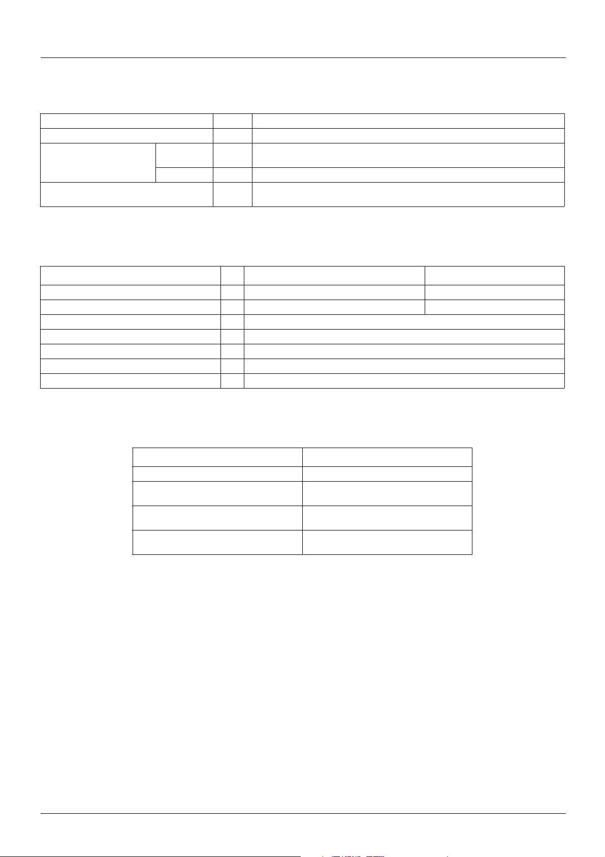
General characteristics
Degree of protection IP 20
Maximum relative humidity Class F humidity without condensation 5…85%
Ambient temperature
around the unit
Maximum operating altitude m 1000 without derating
Electrical characteristics
Type of module VW3 A7 201…212 VW3 A7 231…241
Supply voltage V a 400 a 460
Nominal voltage ± 10% V a 380…415 a 440…480
Operating frequency Hz 40…60 ± 10%
Overload capacity A 1.2 x maximum current (Irms)
Efficiency 97% (3% of thermal losses)
Power factor 1
Fundamental frequency component 0.7…0.95
Operation °C (°F) 5…+ 40 (41…+ 104) without derating
Up to 55°C (131°F) with current derating of 3% per °C (34°F) above 40°C (104°F)
Storage °C (°F) - 25…+ 55 (-77…+ 131)
1000…4000 derating the current by 5% per additional 1000 m
Connection characteristics
Type of module Maximum wire size
VW3 A7 201 25 mm
VW3 A7 202…205,
VW3 A7 231, 232
VW3 A7 206…209,
VW3 A7 233…238
VW3 A7 210…212,
VW3 A7 239…241
2
, connected on a bar, M5
2
35 mm
, connected on a bar, M6
2
, connected on a bar, M8
95 mm
2
150 mm
, connected on a bar, M10
14 1757361 11/2010
Page 15

Sizing
Line voltage: a 400 V
Maximum
current
Irms
a
AA kW AV kg
11 13 7 20 660 VW3 A7 201 20.000
20 24 13 30 690 VW3 A7 202 25.000
32 38 11 50 690 VW3 A7 203 26.000
48 58 21.5 80 690 VW3 A7 204 30.000
65 78 26 100 690 VW3 A7 205 32.000
102 123 32 160 660 VW3 A7 206 43.000
130 157 38 200 660 VW3 A7 207 48.000
195 236 38 315 660 VW3 A7 208 52.000
231 279 86 350 660 VW3 A7 209 90.000
289 350 120 400 1000 VW3 A7 210 100.000
360 433 135 500 1000 VW3 A7 211 115.000
500 600 200 630 1000 VW3 A7 212 125.000
Line voltage:
c
a 460 V
Continuous
braking
power
Fast-acting semi-
conductor fuses
aa
Catalog
number
Weight
Maximum
current
Irms
a
AA kW AV kg
28 33 – 50 690 VW3 A7 231 26.000
41 50 21.5 80 690 VW3 A7 232 30.000
57 69 26 100 690 VW3 A7 233 36.000
88 107 32 160 660 VW3 A7 234 43.000
113 137 38 200 660 VW3 A7 235 48.000
138 166 38 250 660 VW3 A7 236 48.000
157 189 38 250 660 VW3 A7 237 50.000
176 212 38 315 660 VW3 A7 238 90.000
201 243 86 315 660 VW3 A7 239 100.000
289 346 120 500 1000 VW3 A7 240 105.000
500 600 240 630 1000 VW3 A7 241 125.000
c
Continuous
braking
power
Fast-acting semi-
conductor fuses
aa
Catalog
number
Weight
1757361 11/2010 15
Page 16

Sizing
PU
rmsIrms
3 ϕcos⋅⋅⋅=
P400V65A 3×× 45033W==
P395V65A 3×× 44470W==
To calculate the correct value of the powe r that i s g enerat ed, t he f act t hat the a ctu al ins tan taneous power ge nerat ed d epen ds
on the actual voltage of the line supply at each moment must be take n into accou nt. Th e foll owing formula is used t o calcul ate
the power generated (during operation as a generator: cosϕ = 1):
The maximum power generated is calculated according to the instantaneous rms voltage of the line supply and according to
the maximum rms current of the device in question.
Example: The VW3 A7 205 has a maximum generated power of 45 KW and a maximum rms current of 65 A (refer to the
technical data). The nominal voltage of the line supply is, for example, 400 V. This gives:
That is, approximately 45.0 kW.
If the instantaneous rms voltage of the lin e supply is less than 395V for a moment, then the maximum power generated is also
reduced:
That is, approximately 44.5 kW.
16 1757361 11/2010
Page 17

Sizing
001
2
1
3
4
5
6
7
8
9
10
234 567891011
A
Time between braking operations (min.)
Braking time (min.)
27 kW
33 kW
001
2
1
3
4
5
6
7
8
9
10
234567891011
Time between braking operations (min.)
Braking time (min.)
27 kW
33 kW
0
2
1
3
4
5
6
7
8
9
10
01234567891011
Time between braking operations (min.)
Braking time (min.)
45 kW
33 kW
001
1
0.5
1.5
2
2.5
3
3.5
4
4.5
5
234567891011
Time between braking operations (min.)
Braking time (min.)
45 kW
70 kW
001
1
0.5
1.5
2
2.5
3
3.5
4
4.5
5
234567891011
Time between braking operations (min.)
Braking time (min.)
52 kW
90 kW
Example of how to use characteristic curves
Note: These curves are given for a voltage of 400 V or 460 V, depending on the model.
VW3 A7 204, A7 232
(Continuous braking power = 21.5 kW) (1)
Example of how to use the curves:
Required braking power of 27 kW.
The intersection point between the braking time and the time
between 2 braking operations must be on or below the relevant
curve.
A for a braking time of 2 minutes, there must be at least
Point
50 seconds between 2 braking operations.
VW3 A7 204, A7 232 (Continuous braking power = 21.5 kW) (1) VW3 A7 205, A7 233 (Continuous braking power = 26 kW) (1)
VW3 A7 206, A7 234 (Continuous braking power = 32 kW) (1) VW3 A7 207, A7 235 (Continuous braking power = 38 kW) (1)
(1) Power indicated for a temperature of 35°C (95°F).
1757361 11/2010 17
Page 18

Sizing
001
1
0.5
1.5
2
2.5
3
3.5
4
4.5
5
234567891011
Braking time (min.)
52 kW
135 kW
Time between braking operations (min.)
001
1
0.5
1.5
2
2.5
3
3.5
4
4.5
5
234567891011
110 kW
Braking time (min.)
160 kW
Time between braking operations (min.)
001
1
0.5
1.5
2
2.5
3
3.5
4
4.5
5
234567891011
Time between braking operations (min.)
Braking time (min.)
135 kW
200 kW
001
1
0.5
1.5
2
2.5
3
3.5
4
4.5
5
234567891011
Time between braking operations (min.)
Braking time (min.)
170 kW
250 kW
001
1
0.5
1.5
2
2.5
3
3.5
4
4.5
5
234567891011
Time between braking operations (min.)
Braking time (min.)
230 kW
345 kW
001
1
0.5
1.5
2
2.5
3
3.5
4
4.5
5
234567891011
Time between braking operations (min.)
Braking time (min.)
260 kW
400 kW
VW3 A7 208 (Continuous braking power = 38 kW) (1) VW3 A7 209, A7 239 (Continuous braking power = 86 kW) (1)
VW3 A7 210, A7 240 (Continuous braking power = 120 kW) (1) VW3 A7 211 (Continuous braking power = 135 kW)
VW3 A7 212 (Continuous braking power = 200 kW) VW3 A7 241 (Continuous braking power = 240 kW)
(1) Power indicated for a temperature of 35°C (95°F).
18 1757361 11/2010
Page 19

Dimensions
H
G==
H1
b
a
c
4xØ
u 70
u 70
u 150u 150
H
G==
H1 H2
a
b
c
4xØ
u 70
u 70
u 150
VW3 A7 201…205, 231, 232
Mounting recommendations
VW3 a b c G H H1 Ø
A7 201, 202
A7 203…205
270 500 295 260 260 80 7
270 580 295 260 340 80 7
A7 231...232
VW3 A7 206…208, 233…237
VW3 a b c G H H1 H2 Ø
A7 206…208
A7 233…237
245 700 272 260 440 80 180 7
272 700 295 260 440 80 180 7
Mounting recommendations
1757361 11/2010 19
Page 20

Dimensions
320
350==
28080
837
380
395
2xØ8.5
4xØ8.5
u 70 u 70
u 150
H
G==
H2H1
b
a
c
2xØ
4xØ
937
u 70
u 70
u 150
VW3 A7 209, 210, 238, 239
VW3 A7 211, 212, 240, 241
Mounting recommendations
Mounting recommendations
VW3 a b c G H H1 H2 Ø
A7 211, 240
A7 212, 241
20 1757361 11/2010
380 937 395 350 320 80 280 8.5
380 1037 395 350 320 80 280 8.5
Page 21

Mounting and temperature conditions
Required mounting position
The braking unit has been designed to be mounted on a vertical wall only (+/- 15°). The unit can only be mounted on a smooth surface
without the use of any type of spacer. It must be mounted in this way to ensure correct circulation of the cooling air.
Important recommendations
• Leave sufficient free space!
- Leave a horizontal distance of at least 70 mm between the braking units and the other components, and between the braking uni ts and
the enclosure walls.
- Leave a vertical distance of at least 70 mm between the braking units and the other components, and between the braking units and
the enclosure walls.
• Check that there are no obstacles to the entry and exit of the cooling air. Leave a minimum distance of 15cm at the air intake and outlet
apertures.
• If the cooling air is polluted (dust, grease, corrosive gas) this may hamper some of the functions of the braking unit.
- Take appropriate measures, for example: Keep the cooling air separate, fit air filters, clean regularly.
• Do not exceed the acceptable ambient temperature during use.
A dissipated thermal power of 3% of the maximum nominal power must be taken into account. The air temperature must not exceed 40°C
(104°F) in the vicinity of the braking unit. The air intake and outlet apertures at the top and bottom of the braking unit must not be covered
by installation equipment such as cable ducts or other equipment.
The required air flow rate depends on the size of the braking unit (nominal power and nominal voltage).
3
Braking module Required air flow rate (m
VW3A7 4-230, 7-230, 12-230, 18-230, 22-230, 25-230
VW3A7 7-400, 13-400, 22-400, 33-400, 45-400
VW3A7 22-460, 33-460, 45-460
VW3A7 18-500, 33-500, 45-500
VW3A7 38-230, 50-230, 75-230
VW3A7 70-400, 90-400, 135-400
VW3A7 70-460, 90-460, 110-460, 125-460
VW3A7 70-500, 90-500, 110-500, 125-500
VW3A7 75-230 (1)
VW3A7 135-400 (1)
VW3A7 125-460 (1)
VW3A7 125-500 (1)
VW3A7 70-690 (1)
VW3A7 90-230, 115-230
VW3A7 160-400, 200-400, 250-400
VW3A7 140-460, 160-460
VW3A7 140-500, 160-500
VW3A7 150-690, 250-690
200
350
450
700
/h)
(1) Some specific models have sli g ht ly di ffe re n t di m e ns i on s .
1757361 11/2010 21
Page 22

Recommendations for the electrical installation
Protection of the braking unit
CAUTION
RISKS OF INTERFERENCE
The braking unit contains components that are sensitive to electrostatic discharge.
During the installation and wiring phases, personnel must comply with the rules of
international standard IEC 747.1, section 9. Basically, before starting work, personnel
must discharge themselves of any electrostatic vol tage by touching the grou nding cable
screw located on the unit or a grounded surface of the enclosure.
Failure to follow these precautions can result in equipment damage.
22 1757361 11/2010
Page 23

Connection diagrams, fuses and associated cables
The connections can be accessed by removing the side screws and connection terminal cover f rom the unit. The cables must pass through
a cable gland located on the wiring plate.
CAUTION
RISKS OF INTERFERENCE
When you remove the cover, take care not to damage th e cables that lead to the displ ay.
Failure to follow this precaution can result in equipment damage.
Electrical power supply
Fuses
The braking unit is equipped with fuses for semi-conductors.
• The on-load voltage drop must be taken into consideration when choosing the cable cross-section (See section “Checking the
installation”, page 6
• Protection of the braking unit cables (L1,L2,L3) and the connections to the line supply:
- by commercially available cable protection fuses
- the fuses must comply with the appropriate standards for the site.
- the nominal voltage of the fuse must comply with the voltages for the site.
• Protection of the braking unit and the connections to the DC bus (+UG,-UG):
- The fuses are part of the braking unit
).
The installer/user of the circuit is responsible for compliance with the appropriate standards.
WARNING
• Overcurrent protective devices must be properly coordinated.
• Use the fuses recommended in this document.
Failure to follow these instructions can result in death or serious injury.
Connections
• All the connections must be a short as possible and have a low impedance.
• Shielded cables must be used in order to comply the EMC directives (in accordance with current standards such as EN 61800.3).
• Connect the line supply (line reactor) to terminals L1, L2 and L3 on the braking unit. Only a three-phase supply is permitted.
• A defined phase sequence (indirect rotation of the field) must be followed when connect ing the braking unit to the l ine supply. The braking
unit has a phase sequence check. If the rotating field is incorrect , an error mess age is display ed via an LED as follows: "in correct phase
rotation direction" or "phase loss". In this case, two phases connected to the braking unit must be inverted.
• Connect the ground of the power supply cables to the ground connection screw on the braking unit.
• The DC bus wires used to connect the drive and brak ing uni t must be connect ed to the DC fuse carrier. It is essen tial to compl y with th e
correct polarities.
The inversion of the + (PLUS) and the - (MINUS) will prevent correct operation of the braking unit.
1757361 11/2010 23
Page 24

Connection diagrams, fuses and associated cables
See Fan power supply page 25
Wiring diagram
L1
L2
L3
N
PE
1
3
2
4
1
3
2
4
(3) (3) (3)
S/L2
R/L1
5
6
5
6
(1)
F2
F3
F4
(2)
A2
L1L2L3
R1B
T/L3
R1A
R1C
R2A
R2C
PA/+
PC/–
+
–
Q1
KM1
A1
ATV 71Hppppp
L1
N
F1
N
L1
PE
W/T3
U/T1
V/T2
V1
U1
W1
M
3
LI1
+ 24
X2
1
2
3
4
Components for use with the unit (for a complete list of references, see our “Motor starter solutions. Power control and protection
components” specialist catalogue).
Ref. Description
A1 ATV 71 drive
A2 Network braking unit
F1 2 A fuse, a 230 V
F2…F4 For the fuses, refer to the reference tables on page 15
Q1 Residual curren t circuit breaker 300 mA. Provides protection against earth leakage faults.
(1) Optional additional EMC input filter
(2) Line reactor recommended
(3) For ATV 71HC40N4 drives combined with a 400 kW motor and ATV 71HC50N4, see the drive Installation Manual.
24 1757361 11/2010
Page 25

Connection diagrams, fuses and associated cables
Size of DC bus fuses (F1, F2, F3) depending on the drive rating
Fast-acting semi-conductor
For drives
ATV 71H037M3…HU15M3 25
ATV 71HU22M3…HU40M3 50
ATV 71HU55M3, HU75M3 100
ATV 71HD11M3X…HD18M3X 160
ATV 71HD22M3X, HD30M3X 250
ATV 71HD37M3X, HD45M3X 350
ATV 71HD55M3X 500
ATV 71HD75M3X 630
ATV 71H075N4…HU22N4 25
ATV 71H075N4…HU40N4 50
ATV 71HU55N4…HD11N4 80
ATV 71HD15N4…HD22N4 100
ATV 71HD30N4, HD37N4 160
ATV 71HD45N4 200
ATV 71HD55N4 250
ATV 71HD75N4 350
ATV 71HD90N4 315
ATV 71HC11N4, HC13N4 400
ATV 71HC16N4 500
ATV 71HC20N4 630
ATV 71HC25N4, HC28N4 800
ATV 71HC31N4 1000
ATV 71HC40N4, HC50N4 1250
(1) Nominal voltage of fast-acting semi-conductor fuse
fuses (1)
A
Line voltage
a VV
230 690
400 690
440 800
460 800
480 800
Nominal voltage of fast-acting
semi-conductor fuse
Fan power supply
Braking units (except for VW3A7201... 205, VW3A7231 and VW3A7232) have two terminals (blue terminal = neutral [N ], grey fuse terminal
= phase [L]) for supplying internal fan(s) (VW3A7206...7212 : 230 Vac, VW3A7233...7241 : 115 Vac). The fuse inside the fuse terminal is
installed in order to protect the internal wiring and is the following type: 2 A, 500 V, size: 5*30 mm
Control cable
Connect the control cable to the X2 terminals on the braking unit control panel.
Do not place the control cables near the power supply cables as the power supply cables cause interf erence.
Connect the shielding of the control cables with the metal connector on the guide, over as large an area as possible.
Control functions
The control terminals are on the braking unit control card and are indicated by X2. These terminals can be removed easily using a simple
operation. (see diagram “Use of the terminals”, page27
The control card must always be configured for the voltage of the line supply.
The contacts of the fault relay on the X2 terminals can be connected to the outside. It is also possible to perform an external reset or
switching functions by connecting them to the drive or the PLC.
)
1757361 11/2010 25
Page 26

Connection diagrams, fuses and associated cables
!" #
$!
!
%%
&
' ()*
+ ()*
+ ,-&.$*
% %*
!# %
/ %
Layout of the control panel
26 1757361 11/2010
Page 27

Connection diagrams, fuses and associated cables
12
X2
General error relay
Terminals 5 and 6
connected internally to
temperature supervision
External OFF
External
ON/RESET
ON/RESET
Use of the terminals
1
2
3
4
5
6
7
8
9
10
11
Terminals 1 to 4 (refer to the diagram above)
These terminals are connected to two volt-free relays (one is normally open, the other is normally closed) with a maximum load current of
5AAC or 3ADC.
Maximum voltage V DC, V AC.
The relay is shown in open position in the above diagram.
The relay closes if:
1 The line supply is OK
2 There is no fault
and possibly after an ON/RESET pulse.
After an OFF pulse, a general fault is displayed while the relay opens.
Terminals 5 and 6
These terminals are already used for supervision of the i nternal temperature of the heatsink.
Terminals 7 and 8
(use shielded cables only, maximum length: 1.5 m)
OFF signal
These terminals can be used for an external OFF signal (normally open contact) to stop the braking unit.
The OFF signal stops the braking immediately. If this is performed in generator mode, the drive trips immediately afterwards,
due to the excessively high voltage of the DC bus.
+
-
Terminals 9 and 10
(use shielded cables only, maximum length 1.5 m)
ON / RESET signal
These connections can be used for an external ON signal (normally open contact) to start/reinitialize the braking unit.
CAUTION
RISKS OF INTERFERENCE
Do not use external voltage in the co nnecti ons of t erminals 5 to 10: unexpe cted action s
and damage can occur.
Failure to follow these precautions can result in equipment damage.
Terminals 11 and 12
(use shielded cables only )
These connections can be used for an external ON si gnal (external volt age of 12- 24 V DC, for example from a PLC, short duration pulse)
to start or reinitialize the braking unit.
(Connect the "Plus" to terminal 11 and the "Minus" to terminal 12)
1757361 11/2010 27
Page 28

Operation on a neutral IT (isolated or impedance grounded neutral) system
Types of electrical network and their main characteristics
Comply with the restrictions relating to each type of network.
If you want to use braking units on types of network that are not listed in the table below, please contact our technical experts.
Network type Use of the braking unit Note
Star connection with
grounded neutral
Star connection with
isolated or impedance
grounded neutral
With grounded active
neutral
Specification of the cables used
• The cables used must comply with the specifications for the site (for example UL or UL-c)
• The restrictions concerning the minimum cross-section of the grounding cables must be adhered to!
• The efficiency of a shielded cable is dependent on:
- A correctly shielded connection
- The quality of the connection of the shielding
- Low impedance of the shielding (only use tinned copper or nickel-plated copper shielding!).
Permitted Comply with the technical
data for the unit
Permitted after consultation
with the manufacturer and
possible modification of the
unit
Permitted after checking
with the manufacturer
28 1757361 11/2010
Page 29

Electromagnetic compatibility and wiring
To install a braking unit in an EC approved control system, the following measures and warnings must be taken into account:
General • The user is responsible for compliance of the application with EC directives.
• Connect the braking unit and the EMC filter to the grounded mounting plate with a cable whose cross-section is as
large as possible:
Assembly
- Mounting plates with conductive surfaces (coated zinc or stainless steel) provide a permanent contact .
- Varnished cards must not be used for installations that are to comply with EMC standards.
• If you use several mounting plates:
- Connect as large an area as possible of the mounting plate (for example with copper strips).
• Check that the power supply cables and control cables are separated.
Filters
Shielding
Grounding
Braking units are electrical units for use in industrial and commercial equipment. In accordance with the EMC directive, 2004/108/EC, it is
not compulsory to mark these braking units, although in the sense of the directive and the EMC law these components are designed for
installation by an electromechanical engineer and cannot be used autonomously. Compliance with the protection objectives of the EMC
directive must be proved by the installer or the user of the machine or the equipment. If EMC filters provid ed by Schneider-Electric are used,
and if the conditions below and the installation directives are followed, then the compliance of the measures is assured.
Conditions
The braking unit, combined with the connected EMC filters, has been designed for use under the conditions defined by class "A" ("B" on
request).
Definition conforming to the basic standards:
• EN50081-2 for emission
• EN50082-2 for immunity
• Use the EMC filters that are assigned to the braking unit. EMC filters reduce high frequency interference from a
prohibited value to a permitted value.
• Metal cable connectors provide a connection between the shielding and the unit over a large area.
• If there are breaks in the shielding at all the ends in the cable route:
- Connect the cable shielding to the mounting plate over a large area
• If the power supply cables between the EMC filter and the braking unit are longer than 300 mm:
- Use shielded power supply cables
- Connect the shielding directly to the drive/braking unit mounting plate and to the EMC filter mounting plate.
• Shield the control cables:
- Connect the shielding to their terminals via the shortest possible route.
• All metal parts (braking unit, drive, EMC filter) must be connected to a common grou nd (PE).
• Comply with the minimum cable cross-sections defined in the safety directives:
- From an EMC point of view, it is the area of the cable and the contact with the mounting plate that is important for
operation, rather than the cable cross-section.
:
1757361 11/2010 29
Page 30

Electromagnetic compatibility and wiring
Connected protective cable
Busbar connected to the
mounting plate over a large area
Mounting plate
Ground attachment
Power supply cable
Connection of RFI filter to
mounting plate over a large area
Equalization of the potential
to the building ground
Filtered cable to drive
Installation
To avoid coupling interference, the following cables must be at least 15 cm apart:
a) Network/power supply cables
b) Motor and drive cables
c) Control and data cables (low voltage range < 48 V)
To obtain a low impedance HF connection, the grounding cables, the shielding and other metal connections (for example: mounting plate/
mounted units) must be made using as large an area as possible with the metal conductive part. Use grounding cables and a grounding
network with as large a cross-section as possible (minimum 10 mm2) or metal strips.
Use shielded copper or tinned copper cables. Shielded s te el cabl es a re not su itabl e f or h igh fre quenc y ap plic atio ns. Connect th e shielding
using metal clips or connectors to the grounding connections. Do not extend the shielding with a single wire!
If external EMC filters are used, they must be installed no more than 30 cm away from the noise source, and must have low impedance
connections and contacts.
Relays, magnetic contactors, etc, must always be fitted with varistors, RC circuits or diode filters.
All connections must be as short as possible and must be positioned as close as possible to the ground. Unconnected wires act like
antennae.
Avoid current loops in all cables. Connect unused cables to the ground at both ends.
If unshielded cables are used, twist the pairs to attenuate the non asymmetric noise.
Connection of an EMC filter
30 1757361 11/2010
Page 31

Electromagnetic compatibility and wiring
8
3
6
Design of EMC compliant enclosure
1
7
14
14
12
15
2
5
6
1 Enclosure
2 Wiring betwe en th e EM C filter and the drive
3 EMC filter
4 Line supply cable
5 Wiring betwe en th e EM C filter and the braking unit: cable cross-section conforming to the short circuit protection
6 Motor wiring
7 Control wiring
8 Wiring from the DC bus to the braking unit (DC)
9 Common central point mounting plate (Star connection)
10 Equipotential link
11 Additional grounding cable
12 Braking unit
13 Connection to the power supply
14 PLC
15 Drive
16 Power supply fuses
17 Magnetic power supply switch
9 10
16
7
11
9
17
4
13
4
1757361 11/2010 31
Page 32

Electromagnetic compatibility and wiring
Comments
A system is generally divided into one zone for the power electronics and one zone for the control electronics. This is important, whether
the system is installed in one enclosure or spread over several enclosures. It is recommended that a shielding screen is fitted, due to the
high noise emission of the power supply cables. This screen must have a low contact resistance with the frame or the mounting
plate (remove the varnish!).
The installed braking unit and the connected EMC filter must form one unit, that is, they must be connected via a mounting plate with no
insulating varnish.
The connection between the braking unit and the EMC filt er must be shield ed. The shielding must be connected to ground at each e nd. The
cable must not exceed 300 mm.
The braking unit mounting plate must be the connection point for the grounding and the shielding of the machine or the equipment. If the
drive or another component of the equipment cause s interf erence, th e HF connecti on of thi s component will be poor. It can b e improved by
an additional grounding network.
The leakage currents increase when EMC filters are used. When the leakage cu rrent is greater th an 3.5 mA, one of the following conditions
must be met:
- Copper protective cable whose cross-section is greater than 10 mm
- Supervision of the protective cable by a module that trips in the event of a fault.
- Second cable connected in parallel with the protective cabl e via separate terminals. This cable must be VDE0100 / part 540 compliant.
Installation of the control cables
2
The shielding of the digital signal cables, which are connected to the terminals, must be connected to the shielding strips or directly to the
grounded plate, in order to reduce the impedance.
The shielding of the digital signal cables, which are connected to the terminals, must be connected over as large a surface area as possible.
If the screen is grounded via a single wire, there is a 70% increase in the noise.
Commercially available cable clips are suitable for connecting the shielding.
If unshielded signal cables are used, use twisted pairs only.
32 1757361 11/2010
Page 33

Starting tests
CAUTION
RISKS OF INTERFERENCE
• Check the wiring of the braking unit (short circuits and ground faults) before it is
turned on for the first time
• If the wiring is not correct, unexpected operation of the dri ve and/or t he braking unit
is possible.
Failure to follow these precautions can result in equipment damage.
Initial power-up
• Step 1: Connect the line supply.
- The braking unit is ready to operate after approximately 1 s.
• Step 2: Check that the braking unit is ready to be used.
- If the green LED only is on, the braking unit is ready to be used.
- If all the other LEDs are also on, as well as the green LED, there is interference. Eliminate the interference before starting up
(See section: “Troubleshooting”, page 36
• Step 3: Check that the drive is ready to be started up.
- Proceed in accordance with the drive manual.
).
1757361 11/2010 33
Page 34

Configuration
The configuration of the jumpers provides various control possibilities and different internal functions in accordance with the specific error
messages.
Various definitions resulting from the specific configuration possibilities of the jumpers are explained in the following parag raphs.
"Autostart"
Jumper J1 closed: Autostart.
Autostart means that the device starts automatically one second after being connected to the line supply ("automatic power-up").
Configuration of the jumpers, see the table below.
If the braking unit must not start up automatically , even if the phase control i s deactivat ed, terminals 7 and 8 must be linked unt il 4 seconds
after power-up. Then, to activate braking there must be a short pulse on the RESET input.
"Power-up" - "Stop"
"Stop" means that the control of the semi-conductors and the braking unit wi ll be int errupted. It is no longer possible to brak e the frequen cy
inverter with the braking unit.
"Power-up" is the activation of the control of the semi-conductors.
"Memorize"
The braking unit has a fault memo ry i n which speci al faul t s can be ass ign ed. Memorize d error me ssage s mu st be d ele ted u sing RESET or
by breaking the line supply. "Memorize" always results in a stop and tripping of the general fault relay.
"RESET"
When a fault has been deleted, if it was memorized, it must be reset to zero:
• Either by pressing the RESET button
• Or by disconnecting and reconnecting the line supply (three phase).
CAUTION
RISKS OF INTERFERENCE
Resetting to zero in the case of excessive DC bus voltage during generation is not
recommended. If this is performed, the power semi-conductors are exposed to
increased stress, which can result in accelerated aging.
Failure to follow this precaution can result in equipment damage.
"Phase loss"
Phase loss supervision monitors the 3 phases of the line supply.
If one phase fails, the braking unit continues to operate, but with reduced generated power.
The braking unit reacts in different ways when there is a phase loss. One possibility is "two phase operation". The other is to allow the
system to exit operation and the general fault relay indicates the fault.
Configuration using the jumpers, see the table below:
J3 J5 J6 J7 Phase loss supervision
⎯00 ⎯ Sensitive, fault memory ON
⎯⎯⎯⎯Not sensitive, fault memory ON
0XX⎯ Stop, fault memory ON
0 X X 0 Sto p , fault memory OFF
0 Jumper open
⎯ Jumper closed
X Jumper in either position
Note: Fault memory "ON" means that the "phase loss" fault is indicated by an LED until it is cl eared, if the fault no lon ger exists . Fault
memory "OFF" means that the "phase loss" fault is indicated by an LED only as long as the fault exists.
34 1757361 11/2010
Page 35

Configuration
RISKS OF INTERFERENCE
• Jumper J3 can only be removed after the frequ ency i nverter o r t he braki ng uni t has
been turned off if the line supply has been cut-off by opening the series switches
(contactors, line supply switch, etc).
• To avoid a dangerous voltage rise in the devices located in the section that is not
powered up: power generation must be stopped.
• Jumper J3 must always be removed before removing jumper J7. I f not, if phase loss
supervision is active, the "phase loss" fault rema ins di splayed as long as it exist s (it
is not memorized in the fault memory).
Failure to follow these precautions can result in equipment damage.
"Overvoltage supervision"
CAUTION
The braking module has overvoltage supervision for the line supply, which stops the device if the voltage level is greater than 1.15 x UN.
Fault code 3 will be shown as the error message (See the "LED messages", “Troubleshooting”, page 36
loss and overvoltage error messages you can deactivate phase loss supervision by removing jumper 3 from the con trol card. If, after doing
so, there is a stop with indication via the red and yellow LEDs (fault code 3), this will then be due to an overvoltage.
J3 J5 J6 J7 J8 LED message Assessment (overvoltage)
_ X X _ _ Green 1.Red Yellow Overvoltage and/or phase loss/switching fault
_ X X 0 _ Green _ Yellow Overvoltage
0 X X _ _ Green 1.Red Yellow Overvoltage and/or phase loss/switching fault
0 X X 0 _ Green _ Yellow Overvoltage
0 X X 0 _ Green 1.Red Yellow Constant phase loss
0 Jumper open
⎯ Jumper closed
X Jumper in either position
Standard adjustment of the device:
Autostart and no stop in the case of phase loss
). To differentiate between phase
1757361 11/2010 35
Page 36

Troubleshooting
The 4 LEDs on the cover of the braking unit display the operating conditions. For simplified display during operation and the first time the
unit is turned on, similar LEDs are pl aced on the control card. The orange and green LEDs are separate on the control card, while there is
a two-color LED (green/orange) on the cover.
CAUTION
RISKS OF INTERFERENCE
If the braking unit trips during a slow-down, it must not be reset to zero before the end
of the slow-down, or before the DC bus voltage has fallen to a normal value.
To avoid any problems, you can block the release of the inverter pulse by connecting
the general fault relay contact on the braking unit to the corresponding connection on
the frequency inverter.
Failure to follow these precautions can result in equipment damage.
Tripping on VCE:
The braking unit trips via the VCE protection circui t, if the specific maximum current of the d evice is exceeded. The principle o f this protection
circuit means that for a short time (less than a millisecond), the IGBT is subjected to stress beyond its specifications for normal operation.
In an exceptional case this is no problem for the braking unit. However, if there are frequent or periodic current surges at braking voltage,
the high power semi-conductors will age rapidly and become prematurely faulty.
The cause of periodic tripping on VCE may be an overload, a fall in line voltage, an oscillating or faulty dri v e, an oscillating input reference
or poor design of the equipment.
LED messages
LED display Assessment
LED display
fault code
1 X Ready to operate System in operation
2 X Ready to operate, but no power generated ⇒ check the DC fuse
3 X X X Heatsink overheating ⇒ error message
4 X X Fault code 3 ⇒ the heatsink temperature
5 X X The system has stopped, (external OFF) ⇒
6 X X An overvoltage has been detected (J8 closed) => a reset to zero is required when the grid
7 X X X Incorrect phase rotation direction or a phase
8 X X X Overcurrent detected => reset required
9 X X X X Faults 7 and 8 Overcurrent and phase loss detected
10 X X X X X Several faults have been detected
11 System stopped, at least 2 phases missing System stopped, at least 2 phases
12 X X Trip-I2t => reset required
13 X X Voltage drop during switching but no trip,
OperationPhase
green red red orange yellow
loss
VCE OverheatingFault First start (after approx. 1 s) During operation
reset to zero required
voltage falls to its nominal value
missing.
simultaneously
cannot be reset to zero while overheating
continues
has fallen to normal and the fault can be
reset to zero
The system has stopped, (external OFF)
⇒ reset to zero required
Phase loss detected => reset required
simultaneously
Several faults have been detected
simultaneously
missing
while jumpers 3 and 7 are open (See the
“Configuration”, page
possible, improvement of the line voltage
recommended.
34) => operation
36 1757361 11/2010
Page 37

1757361 11/2010 37
Page 38

AT V71_regen_units_EN_1757361_03
1757361 11/2010
 Loading...