

Page 1
Ven ta
!
VB-7000 Installation Instructions
Installation
Inspect the package for damage. If damaged, notify the appropriate carrier
immediately. If undamaged, open the package and inspect the device for
obvious damage. Return damaged products.
Requirements
Tools (not provided): Pipe wrenches•
Training: Installer must be a qualified, experienced technician•
Appropriate accessories•
Caution
Install the valve with the flow in the direction of the flow arrow(s). See Table •
One for details on flow.
Do not exceed the ratings of the device.•
Avoid locations where excessive moisture, corrosive fumes or vibration are •
present.
1
Danger
Do not use for combustible gas applications. The valve •
packings are not rated for combustible gas applications, and
if used in these applications, gas leaks and explosions may
result.
Mounting
The valve should be mounted in a weather protected area, if the actuator 1.
is not rated for outdoor use, in a location that is within the ambient limits of
the actuator. When selecting a location, allow sufficient room for the valve,
linkage, actuator, and other accessories and for service of the product.
The preferred mounting position for the valve is with the valve stem vertical 2.
above the valve body. Avoid mounting the valve so that the valve stem is
below horizontal.
For steam applications only, position the valve body so the valve stem and 3.
actuator are at 45° from vertical.
The two-way valves must be piped with the “A” port as the inlet and the 4.
“AB” port as the outlet. Mixing valves must be piped with two inlets ( “A”
and “B” ports) and one outlet (“AB” port). Diverting valves must be piped
with one inlet (“B” port) and two outlets (“A” and “AB” ports).
Valve-specific instructions are available on pages 2 and 3. 5.
Checkout
Make sure the valve stem operates smoothly before installing the valve 1.
linkage and the actuator.
If the stem does not operate smoothly, it may indicate that the valve was 2.
twisted or crushed during installation or that the stem was bent by rough
handling. These conditions may require that the valve be replaced.
After the piping is under pressure, check the valve body and the connec-3.
tions for leaks.
After the valve linkage and the actuator are installed, check their opera-4.
tion. Allow valve to move full stroke, ensure performance per Table One.
Page 2
Ven ta
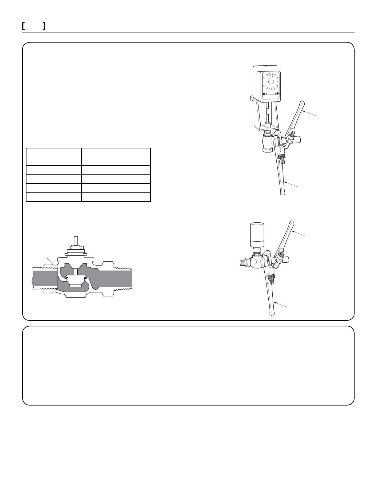
Normal Thread Engagement.
Pipe threads too long.
Pipe interferes with seat.
Wrong
Use pipe wrench to
prevent valve from turning
Tighten pipe using
this pipe wrench
Valve
Assembly
VB-7211-0-3-P
Union Angle
Use pipe wrench to
prevent valve from turning
Tighten pipe using
this pipe wrench
Valve
Assembly
VB-7211-0-4-P
Union NPT
VB-7000 Series Globe Valves
VB-72X1 Union End NPT Valve Bodies
The VB-7211 and VB-7221 series of union valve bodies conform to American Standard Taper Pipe Threads (NPT).
1. Apply pipe dope sparingly to all but the last two threads of a properly
threaded, reamed, and cleaned pipe. Make sure that pipe chips, scale, etc.
do not get into the pipe since this material may lodge in the valve seat and
prevent proper closing and opening of the valve.
2. Start the joint by hand screwing the pipe into the valve. If the thread
engagement feels “right,” turn the pipe by hand as far as it will go.
3. Use a pipe wrench to fully tighten the valve to the pipe. Do not over
tighten or strip threads.
Normal Thread Engagement Between Male Pipe Thread and Valve Body.
Valve Size Inches
(NPT)
1/2” 1/2”
3/4” 9/16”
1” 11/16”
1-1/4” 11/16”
Normal Engagement
2
VB-7XX4 Union Sweat Valve Bodies
1. Remove both tail pieces and union nuts from the valve body. Apply flux to the tail pieces and pipe before sweating into place.
Make sure the union nuts are mounted on the tail pieces before sweating.
Caution: Do not sweat the tail pieces in place while they are mounted to the valve body. The excess heat will damage the valve
body.
2. Re-install the valve body. Start the joint by hand screwing the union nut onto the valve body. If the thread engagement feels
“right,” turn each union nut by hand as far as it will go.
3. Using a pipe wrench to hold the valve, fully tighten the union nut to the valve. Do not over tighten or strip the threads. Take
care not to apply torsion across the valve body.
Schneider Electric 1354 Clifford Ave. Loves Park, IL 61111 1-88 8-444 -1311 www.schneider-electric.com
F- 276 51-1 June 2011 ao
© 2011 Schneider Electric. All rights reserved.
Page 3
Ven ta
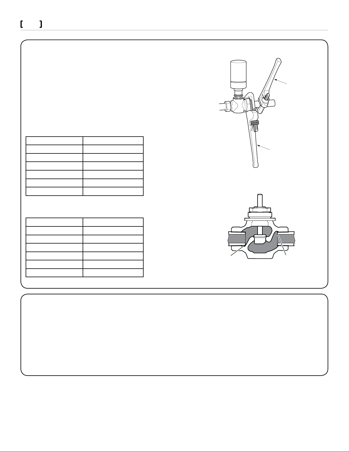
Use pipe wrench to
prevent valve from turning.
Tighten pipe using
this pipe wrench.
Valve
Assembly
Threaded
Right
Wrong
Pipe threads too long.
Pipe interferes with seat.
VB-7000 Series Globe Valves
VB-7XX3 and VB-7XX5 Threaded Valve Bodies
1. Apply pipe dope sparingly to all but the last two threads of a properly
threaded, reamed, and cleaned pipe. Make sure that pipe chips, scale, etc.
do not get into the pipe since this material may lodge in the valve seat and
prevent proper closing and opening of the valve.
2. Start the joint by hand screwing the pipe into the valve. If the thread engagement feels “right,” turn the pipe by hand as far as it will go.
3. Use a pipe wrench to fully tighten the valve to the pipe. Do not over
tighten or strip threads.
VB-7XX3 Normal Thread Engagement Between NPT Male Pipe Thread
and Valve Body.
Valve Size Inches (NPT) Normal Engagement
1/2” 1/2”
3/4” 9/16”
1” 11/16”
1-1/4” 11/16”
1-1/2” 11/16”
2” 3/4”
3
VB-7XX5 Normal Thread Engagement Between Rp Male Pipe Thread
and Valve Body.
Valve Size in mm (Rp) Normal Engagement
15 13
20 14
25 17
32 17
40 17
50 19
VB-7XX2 Flared Valve Bodies
1. Cut end of tubing square using a tube cutter.
2. Slip the flare nut onto the end of the copper pipe. Move it back out of the way to allow working room.
3. Place the base of the flaring tool around the copper tube at the appropriate diameter size.
4. Attach the flare cone over the copper tube opening using screw fitting. Tighten it down until the cone is firmly seated inside
the base the vise base.
5. Remove the copper tube from vise base and examine for splits. Bring the nut back to the end of the flared tubing.
6. Verify the flare fits snugly in bottom of the nut. Now attach and tighten the nut to the valve.
7. Pressure the system and check for leaks.
Schneider Electric 1354 Clifford Ave. Loves Park, IL 61111 1-88 8-444 -1311 www.schneider-electric.com
F- 276 51-1 June 2011 ao
© 2011 Schneider Electric. All rights reserved.
Page 4

Ven ta
VB-7000 Series Globe Valves
Table One
Valve
Body Part
Number
Series
VB-7211 VA,VF,VK,VK4,VS or VU-7211 2-Way Stem Up
VB-7212 VA,VF,VK,VK4,VS or VU-7212
VB-7213 VA,VC,VF, VK,VK4,VP,VS or VU-7213
VB-7214 VA,VC,VF, VK,VK4,VP,VS or VU-7214
VB-7215 VA,VC,VF, VK,VK4,VP,VS or VU-7215
VB-7253 VA,VC,VF, VK,VK4,VP,VS or VU-7253
VB-7255 VA,VC,VF, VK, VK4,VP,VS or VU-7255
VB-7273 VA,VC,VF, VK, VK4,VP,VS or VU-7273
VB-7275 VA,VC,VF, VK,VK4,VP,VS or VU-7275
VB-7221 VA,VF, VK,VK4,VS or VU-7221 2-Way Stem Up
VB-7222 VA,VF,VK,VK4,VS or VU-7222
VB-7223 VA,VF,VK,VK4,VP,VS or VU-7223
VB-7224 VA,VF,VK,VK4,VP,VS or VU-7224
VB-7225 VA,VF,VK,VK4,VP,VS or VU-7225
VB-7263 VA,VF,VK,VK4,VP,VS or VU-7263
VB-7265 VA,VF,VK,VK4,VP,VS or VU-7265
VB-7283 VA,VF,VK,VK4,VP,VS or VU-7283
VB-7285 VA,VF,VK,VK4,VP,VS or VU-7285
VB-7312 VA,VF,VK,VK4,VS or VU-7312 3-Way Mixing B & A AB Flow B to ABFlow A to AB
VB-7313 VA,VC,VF,VK,VK4,VP,VS or VU-7313
VB-7314 VA,VC,VF,VK,VK4,VP,VS or VU-7314
VB-7315 VA,VC,VF,VK,VK4,VP,VS or VU-7315
VB-7323 VA,VC,VF,VK,VK4,VP,VS or VU-7323 3-Way Divert-
VB-7325 VA,VC,VF,VK,VK4,VP,VS or VU-7325
VB-7332 VF,VK,VK4,VS or VU-7332 3-Way Se-
* Valve bodies are de signated by the prefix VB. Wh en associated with an as sembly, the prefix is assign ed based on type of ac tuator. For
example, the series pa rt number of a valve assembly with a two -way, normally o pen, NPT Threade d valve with a pneu matic actuator is VK-7213.
** Stem mid s troke no flow both A and B port s are closed
Valve Assembly Part Number Series* Type of Valve Inlet Port(s) Outlet
Port(s)
A AB Valve Open Valve Closed
Open
A AB Valve
Closed
B A & AB Flow B to ABFlow B to A
ing
B & A AB Flow ** B to ABFlow ** A to
quencing
Flow Stem UpFlow Stem
Down
Valve Open
Closed
AB
4
Water and Steam System Maintenance
All heating and cooling systems are susceptible to valve and system problems caused by improper fluid treatment and system
storage problems. These guidelines are provided to help avoid valve and water system problems from improperly treated water or
storage procedures in cooling, hot water, and steam systems, and to obtain maximum life from Schneider Electric valves. While all
cooling and heating systems are susceptible to problems, closed chilled water systems, including those containing brine or glycol,
are especially prone to system and valve problems. The best way to avoid problems is to follow the advice of professional water treatment and control specialists.
To maintain non-damaging conditions, follow these guidelines:
Clean the system prior to start up. Use a nitrite or molybdate-based treatment program.•
Use filtration equipment where needed.•
Properly store off-line systems and monitor water treatment results using corrosion test coupons.•
Boiler water treatment for steam systems should be continuous. Follow industry guidelines such as “Marks Standard Handbook •
for Mechanical Engineers.” For oxygen removal, catalyzed sodium sulfate is usually recommended.
Consult EN-205, Water System Guidelines Engineering Information, F-26080, for further details.•
Schneider Electric 1354 Clifford Ave. Loves Park, IL 61111 1-88 8-444 -1311 www.schneider-electric.com
F- 276 51-1 June 2011 ao
© 2011 Schneider Electric. All rights reserved.
 Loading...