

Page 1

Valves & Actuators Catalog
EMEA/APAC
EcoBuilding | 2019
Page 2

About Schneider Electric
Schneider Electric is leading the Digital Transformation of Energy Management
and Automation in Homes, Buildings, Data Centers, Infrastructure and
Industries.
With global presence in over 100 countries, Schneider is the undisputable
leader in Power Management – Medium Voltage, Low Voltage and Secure
Power, and in Automation Systems. We provide integrated efficiency solutions,
combining energy, automation and software.
In our global Ecosystem, we collaborate with the largest Partner, Integrator and
Developer Community on our Open Platform to deliver real-time control and
operational efficiency.
We believe that great people and partners make Schneider a great company
and that our commitment to Innovation, Diversity and Sustainability ensures
that Life Is On everywhere, for everyone and at every moment.
Discover Life is On
Discover EcoStruxure
2 F-27878-6
Page 3
About This Catalog and Online Resources
Welcome to the Schneider Electric Valves and
Actuators Catalog
Superior engineering, product design patents, ISO9001 certification, and Six Sigma lean manufacturing ensure our products
conform to the highest standards of internationally recognized
quality to deliver solid performance, unsurpassed value and
exceptional reliability.
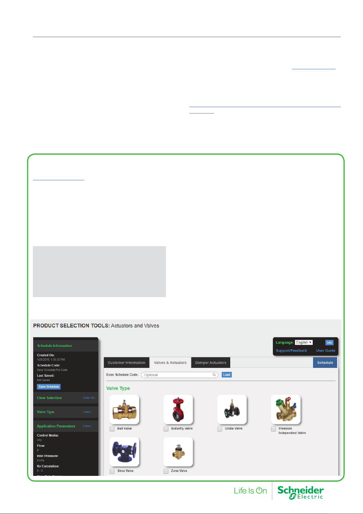
On-line Valve and Actuator Selection Tool
Product Selection Tool
The Valve and Actuator Selection Tool is a dynamic sizing tool
designed to provide a very quick and simple way of choosing
the most appropriate product for your application. A wealth of
information is at your fingertips with full technical details and
quick access to key product documentation.
Sizing and Selection for all HVAC valve and actuators
• Ball Valves
• Butterfly Valves
• Globe Valves
• Pressure Independent Balancing Control Valves
• Zone Valves
• Shoe Valves
• Damper Actuators
The Exchange Extranet
It is recommended to view this catalog in its electronic PDF
version (Acrobat Reader required), from the Exchange Extranet.
Explore the Exchange Extranet for quick and easy access to assets; from software and firmware to technical documentation, as
well as sales and marketing collateral.
Note: Installers and technicians should stay updated on the
“Recommendations / Best practices and Hazard Warnings” on
page 109”
Features
• Intuitive selection based on calculators and/or drop down
menus
• Customer and partner profiles possible in any schedule
creation
• Create a Schedule of hydronic systems using the Valve and
Actuatgor selection feature
• Create own or add to the hydronics a schedule of damper
actuators
• Ability to view, edit, change, communicate and adjust
schedules. Download completed schedules to Excel, pdf,
BOM.
• Save schedules in progress to be worked on later or for use
as a template for future projects.
Browser Compatibility
• Chrome (preferred). Use of other browsers may exhibit
unintented behaviors.
F-27878-6 3
Page 4
schneider-electric.com | 11Actuators Product Family Matrix - North America
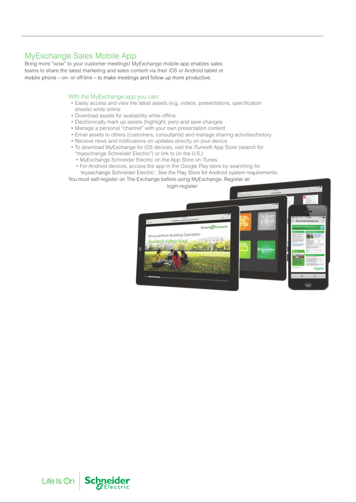
MyExchange Sales Mobile App
Bring more “wow” to your customer meetings! MyExchange mobile app enables sales
teams to share the latest marketing and sales content via their iOS or Android tablet or
With the MyExchange app you can:
• Easily access and view the latest assets (e.g. videos, presentations, specification
sheets) w
hile online
•
Download assets for availability while offline
•
Electronically mark up assets (highlight, pen) and save changes
•
Manage a personal “channel” with your own presenta
tion content
•
Email assets to others (customers, consultants) and manage sharing activities/history
•
Receive news and notifications on updates directly on your device
•
To download MyExchange for iOS devices, visit the iTunes® App Store (search f
or
“m
yexchange Schneider Electric”) or link to (in the U.S.):
•
MyExchange Schneider Electric on the App Store on iTunes
.
•
For Android devices, access the app in the Google Play store by searching for
You must self-register on The Exchange before using MyExchange. Register at:
login-register
About This Catalog and Online Resources
4 F-27878-6
Page 5
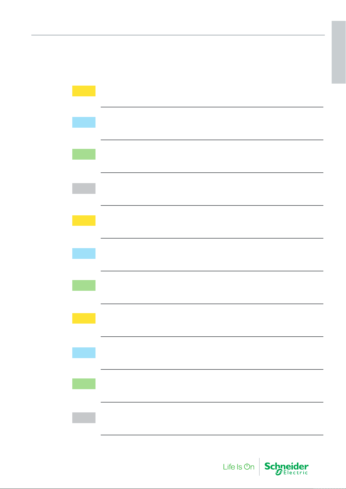
Table of Contents
1. PIBCV Valves and Actuators 7
2. Zone Valves and Actuators 19
3. Radiator Valve Actuators 27
4. Globe Valves 31
CONTENTS
5. Globe Valve Actuators 51
6. Ball Valves and Actuators 61
7. Butterfly Valves and Actuators 67
8. Shoe Valves and Actuators 75
9. Damper Actuators 79
10. Specialist Products 89
11. Supporting Information 105
F-27878-6 5
Page 6

Actuators
1. PIBCV Valves and
6 F-27878-6
Page 7

1. PIBCV Valves and Actuators
Actuators
Pressure Independent Balancing Control Valves provide the
optimum control of fluid flow, unaffected by changes in system
pressure. With inherent hydronic system balancing characteristics,
PIBCV products provide the ultimate solution for the most energy
efficient room temperature control.
Additional benefits of PIBCV include reducing the time taken for
system balancing and commissioning.
1. PIBCV Valves and
F-27878-6 7
Page 8
1. PIBCV Valves and Actuators
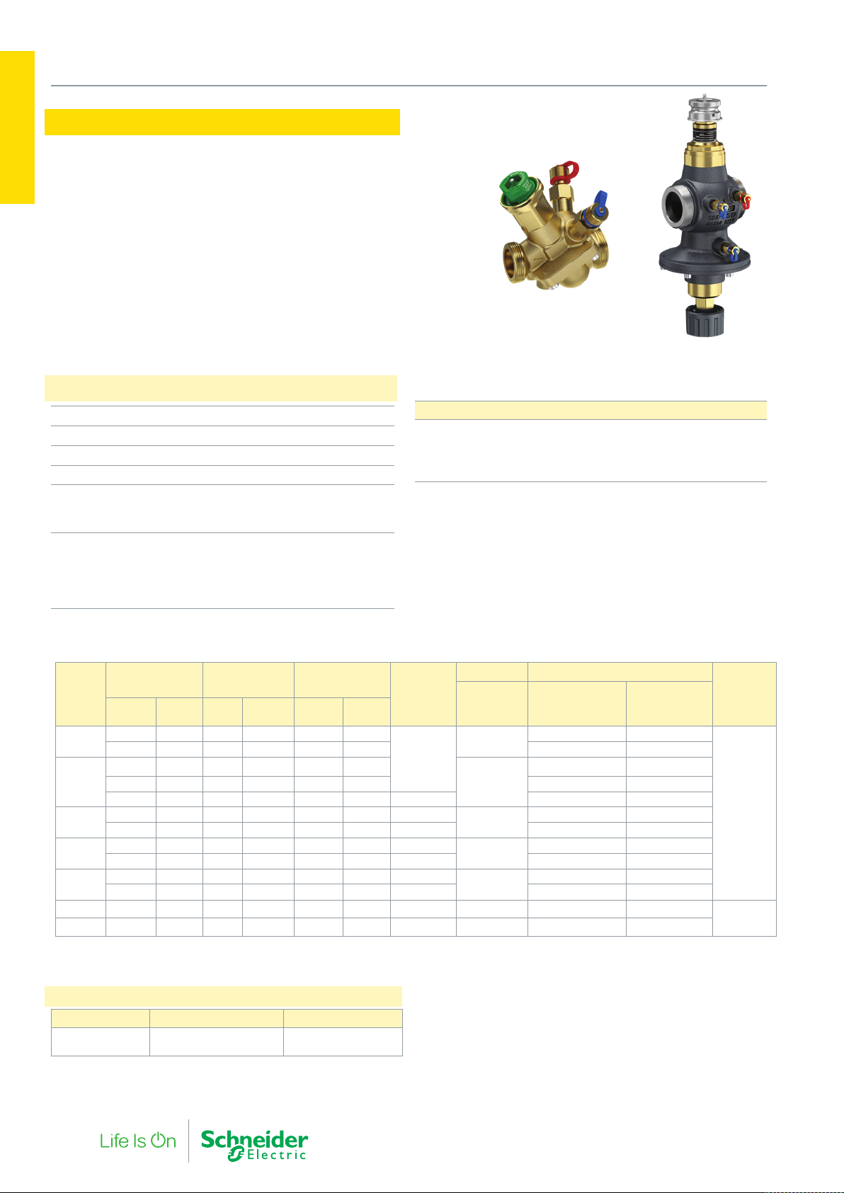
VP228E, VP229E, VP220E
Actuators
1. PIBCV Valves and
The VP228E, VP229E, and VP220E are threaded pressure
independent balance and control valves for use in heating and
cooling circuits.
• Stable hydronic flow, independent of any change in system
pressure.
• Without an actuator, the valve can be operated an automatic
balancing valve for flow limiting applications.
• Simple to calculate and adjust to the needed flow setting
Specifications
Pressure Class PN16
Function Normally Open / Stem Up
End Connection External Thread, ISO228/1
Media Temperature -10…120 °C
Leakage (ISO 5208)
DN10…DN32
DN40…DN50
Stroke
VP228E
VP229E (DN15…DN20)
VP229E (DN25…DN32)
VP220E
Tight - no visible leakage
Max. 0.05% of Q
nom
2.25 mm
4.0 mm
4.5 mm
10 mm
DN10-32 DN40-50
Materials DN10…32 DN40…50
Valve body
Control Valve, Cone
Seat
Seals
DZR Brass
Brass CW 614N
DZR Brass
EPDM
GG 25
Brass CW 614N
SS 1.4305
EPDM
Litres/Hour Litres/Second
DN
Qmin
DN10
DN15
DN20
DN25
DN32
DN40 3,200 7,500 0.8 2.08 3.0 7.5 30-600 G 2A VP220E-40CQS
DN50 5,000 12,500 1.4 3.47 5.0 12.5 30-600 G 2 1/2A VP220E-50CQS
Note: A Higher flow (Q max) is achievable on some sizes by increasing the pressure drop through the valve; please refer to specific technical data sheets.
∆P : Differential Pressure Operating range. The differential pressure across the valve must be within the range specified for predictable, stable and fully
adjustable flow to the limits detailed within
30 150 0.008 0.04 0.03 0.15
55 275 0.015 0.08 0.06 0.28 VP228E-10BQSNT VP228E-10BQS
55 275 0.015 0.08 0.06 0.28
90 450 0.025 0.13 0.09 0.45 VP228E-15BQSNT VP228E-15BQS
227 1,135 0.063 0.32 0.23 1.14 35-600 VP229E-15BQHNT
180 900 0.050 0.25 0.18 0.90 16-600
340 1,700 0.094 0.47 0.34 1.70 35-600 VP229E-20BQHNT
340 1,700 0.09 0.47 0.34 1.70 20-600
545 2,700 0.15 0.76 0.54 2.70 35-600 VP229E-25BQHNT
640 3,200 0.18 0.89 0.64 3.20 25-600
800 4,000 0.22 1.1 0.80 4.00 35-600 VP229E-32BQHNT
Qnom
(100%)
Qmin
Qnom
(100%)
Cubic Meters/
Hour
Qmin
Qnom
(100%)
Δ P
(Qnom)
(kPa)
16-600
Connection Part No.
Ext. Thread
(ISO 228/1)
G 1/2A
G 3/4A
G 1A
G 1 1/4A
G 1 1/2A
Without T/P ports With T/P Ports
VP228E-10BQLNT VP228E-10BQL
VP228E-15BQLNT VP228E-15BQL
VP228E-20BQSNT VP228E-20BQS
VP229E-25BQSNT VP229E-25BQS
VP229E-32BQSNT VP229E-32BQS
Suitable
Actuator
MP120
MP130
MP300-SR
MP500C
MP500CSR
Accesories
Part Number Description Quantity per Pack
911 4060 000 Commissioning Label Set
/ Flow Tag Hanger ID
48
8 F-27878-6
Page 9
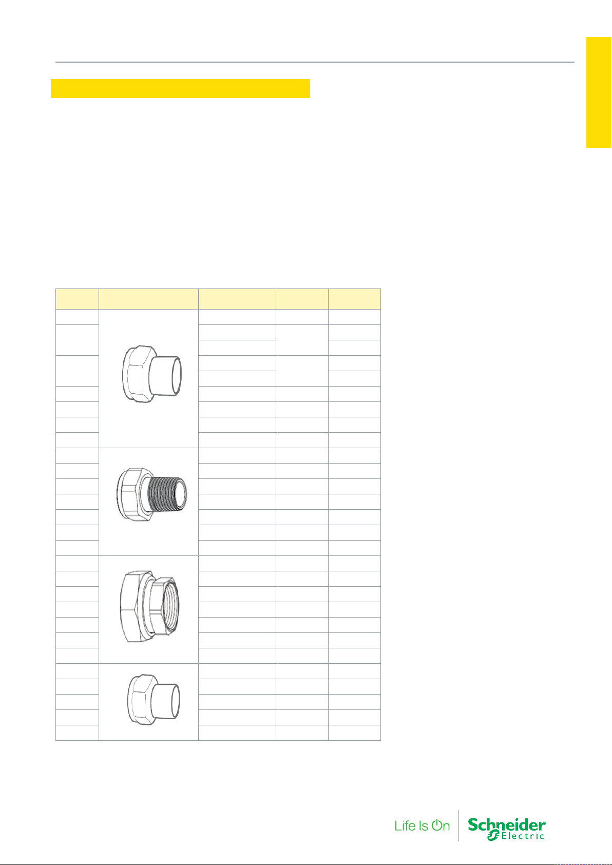
Pipe Connections
1. PIBCV Valves and Actuators
Actuators
The VP228E, VP229E and VP220E have Male threaded end
connections for the attachment of various pipe connections.
Pipe connections are supplied in pairs and are typically a
two piece + gasket separable design allowing the valve to be
removed with minimal disruption to the pipework. On some
sizes a one piece + gasket inseparable design is necessary
and additional couplings may be required for practical
disassembly.
Valve DN Pipe Connection type Part Number
DN10
DN15
DN20
DN25 911 2113 025 G1.1/4 28 mm
DN32 911 2113 032 G1.1/2 35 mm
DN40 911 2113 040 G2 42 mm
DN50 911 2113 050 G2.1/2 54 mm
DN10
DN15 911 2112 015 G3/4 R 1/2
DN20 911 2112 020 G1 R 3/4
DN25 911 2112 025 G1.1/4 R 1
DN32 911 2112 032 G1.1/2 R 1. 1/4
DN40 911 2112 040 G2 R 1.1/2
DN50 911 2112 050 G2.1/2 R 2
DN10
DN15 911 2111 015 G3/4 Rp 1/2*
DN20 911 2111 020 G1 Rp 1/2
DN25 911 2111 025 G1.1/4 Rp 3/4
DN32 911 2111 032 G1.1/2 Rp 1
DN40 911 2111 040 G2 Rp 1.1/4
DN50 911 2111 050 G2 1/2 Rp 1.1/2
DN20
DN25 911 2115 025 G1.1/4 33.7 mm
DN32 911 2115 032 G1.1/2 42.4 mm
DN40 911 2115 040 G2 48.3 mm
DN50 911 2115 050 G2.1/2 60.3 mm
* One piece compact design (inseparable); additional coupler may be needed to ease assembly / dissasembly.
Two end connection sets per pack. Order one pack per valve.
Solder
R taper Male thread
Female thread
Weld
911 2113 010 G1/2 15 mm*
911 2113 015
911 2113 115 22 mm *
911 2113 020
911 2113 120 22 mm
911 2112 010 G1/2 R 3/8
911 2111 010 G1/2 Rp 1/2*
911 2115 020 G1 26.9 mm
Valve
Connection
G3/4
G1
End Fitting
Connection
15 mm
15 mm
1. PIBCV Valves and
F-27878-6 9
Page 10
1. PIBCV Valves and Actuators
VP220F, VP221F, VP222F
Actuators
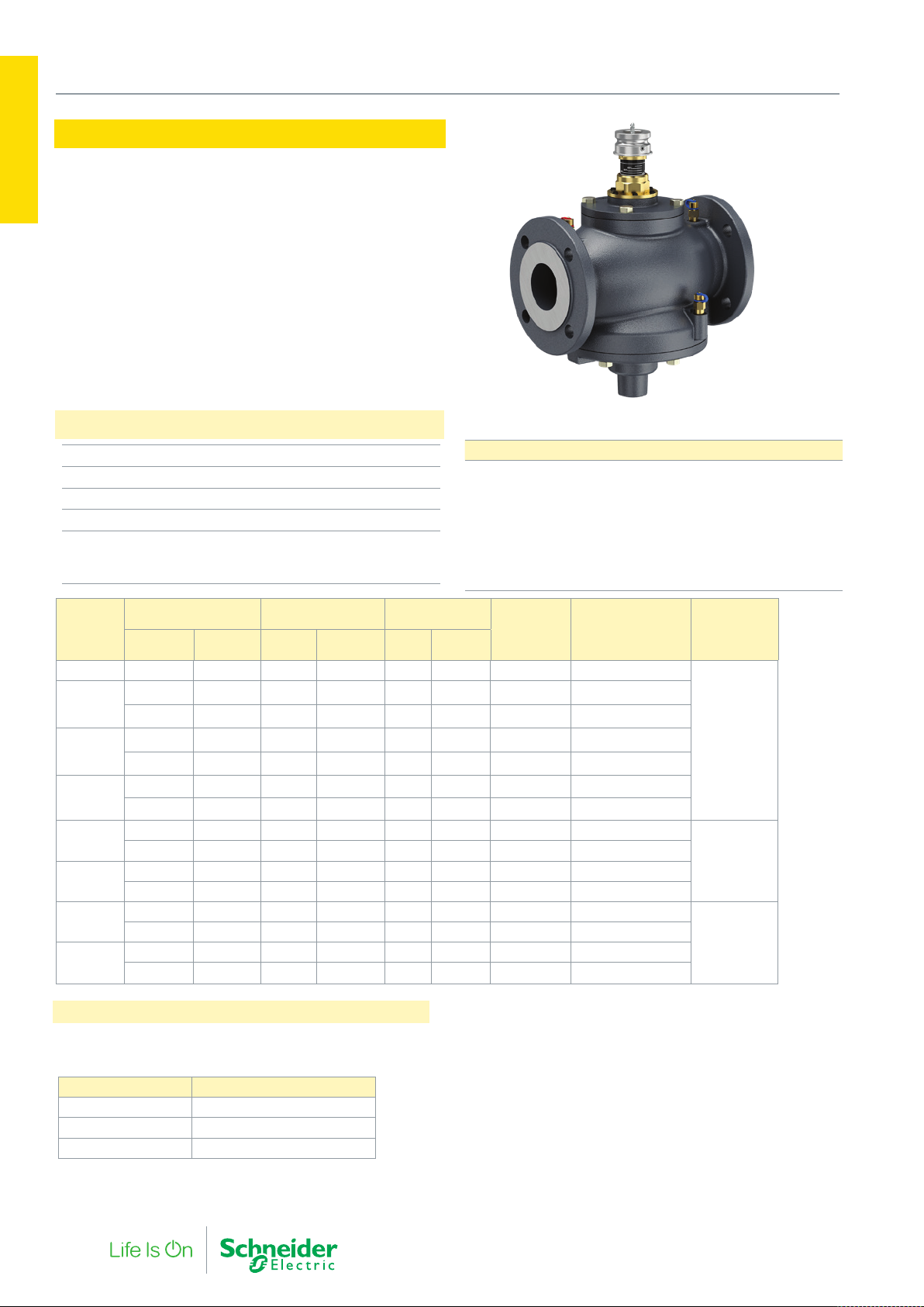
The VP220F, VP221F, and VP222F are flanged pressure inde-
1. PIBCV Valves and
pendent balance and control valves for large flows in heating
and cooling circuits.
• Stable Hydronic flow independent of any change in system
pressure.
• Without an actuator, the valve can be operated as an
automatic balancing valve for flow limiting applications.
Specifications
Pressure Class PN16
Function Stem Up Valve Open
End Connection Flanged PN16, ISO 7005-2
Media Temperature -20…120 °C
Leakage (ISO 5208)
DN50…100
DN125…250
0.05 % of Q
0.01 % of Q
nom
nom
Materials DN50…100 DN125 DN150…250
Valve body
Seals,
Membranes
Cone
Seat
Springs
Gaskets
GG25
EPDM
CW 614N
1.4305
1.4568/1.4310
NBR
1 (W.Nr.1.4404NC)
GG25
EPDM
1.4571
1.4305
1.4401
Graphite
GG25
EPDM
1.4021
1.4027
1.4310
Non-
asbestos
Litres/Hour Litres/Second
DN
Qmin
DN50 5,000 12,500 1.4 3.5 5.0 12.5 30-600 VP220F-50CQS
DN65
DN80
DN100
DN125
DN150
DN200
DN250
10,000 25,000 2.8 6.9 10.0 25.0 60-600
11,200 28,000 3.1 7.8 11.2 28.0 30-600
16,000 40,000 4.4 11.1 16.0 40.0 60-600
15,200 38,000 4.2 10.6 15.2 38.0 30-600
23,600 59,000 6.6 16.4 23.6 59.0 60-600
36,000 90,000 10.0 25.0 36.0 90.0 60-600 VP221F-125CQS
44,000 110,000 12 31 44 110 60-600 VP221F-125CQH
58,000 145,000 16 40 58 145 40-600 VP221F-150CQS
76,000 190,000 21 53 76 190 60-600 VP221F-150CQH
76,000 200,000 21 56 76 200 40-600 VP222F-200CQS
100,000 270,000 28 75 100 270 60-600 VP222F-200CQH
112,000 300,000 31 83 112 300 40-600 VP222F-250CQS
148,000 370,000 41 103 148 370 60-600
Qnom
(100%)
8,000 20,000 2.2 5.6 8.0 20.0 30-600
Qmin
Qnom
(100%)
Cubic Meters/
Hour
Qmin
Qnom
(100%)
Δ P (Qnom)
(kPa)
Part Number
VP220F-65CQS
VP220F-65CQH
VP220F-80CQS
VP220F-80CQH
VP220F-100CQS
VP220F-100CQH
VP222F-250CQH
Suitable
Actuator
MP500C
MP500C-SR
MP2000
MP2000-SR
MP4000
Accesories, Stem Lock Handles
Converts a standard PIBCV valve to automatic flow regulation valve / flow controller which provides a fixed flow against varying
pressure, Stem Lock Handle are fitted in replacement of an actuator.
*DN10-32 valves are supplied with a plastic flow setting cap for the same purpose.
Part Number Valve Size
911 4070 000 DN40…100
911 4071 000 DN125…150
911 4072 000 DN200…250
10 F-27878-6
Page 11
MP130 Actuators
1. PIBCV Valves and Actuators
Actuators
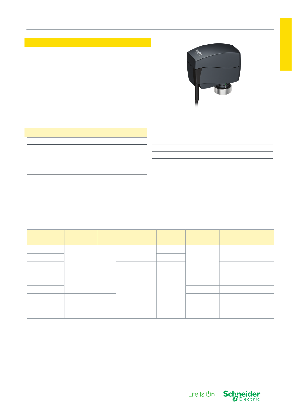
The MP130 is a family of compact and low power motoric actuators that drive the DN10…32 SmartX PIBCV in various hydronic
HVAC applications.
The modulating actuators have fine positional control and are
self calibrating to the adjustable stroke/flow setting in the VP228E
and VP229E valves which provide optimal hydronic control.
• Low Noise Operation
• Overload Protection
• Manual override in all models
Specifications
Close off force 130 N
Stroke 5 mm
Max. medium temperature 120 °C
Environment
Operating Temperature
Storage / transportation
0… 55 °C
–40 …70 °C
1. PIBCV Valves and
Relative humidity max. 95 %
Enclosure rating IP 42
Weight 0.3 kg
Part Number
MP130-24M
MP130-24M-10M 10
MP130-24MP
MP130-24MP-10M 10
MP130-24T
MP130-230T 230 Vac 8 VA
MP130-24F
MP130-24F-10M 10
MP130-230F 1.5 230 Vac 8 VA (0W)
Note: Actuators with 5 m and 10 m cable length are produced on request. Please note this increases lead time.
Control Signal
(Y)
0 (2)…10 Vdc 24
two-position 12
floating 24
Speed
(s/mm)
Position
Feedback (U)
0 (2)…10 Vdc
Cable Length
(m)
-
-
1.5
1.5
1.5
Voltage (50/60 Hz)
24 Vac
24 Vac 1 VA (0W)
Power consumption running
(standby)
2 VA (.5 w)
1.5 VA (.4 W)
1 VA
F-27878-6 11
Page 12
1. PIBCV Valves and Actuators
MP120/MP140
Actuators
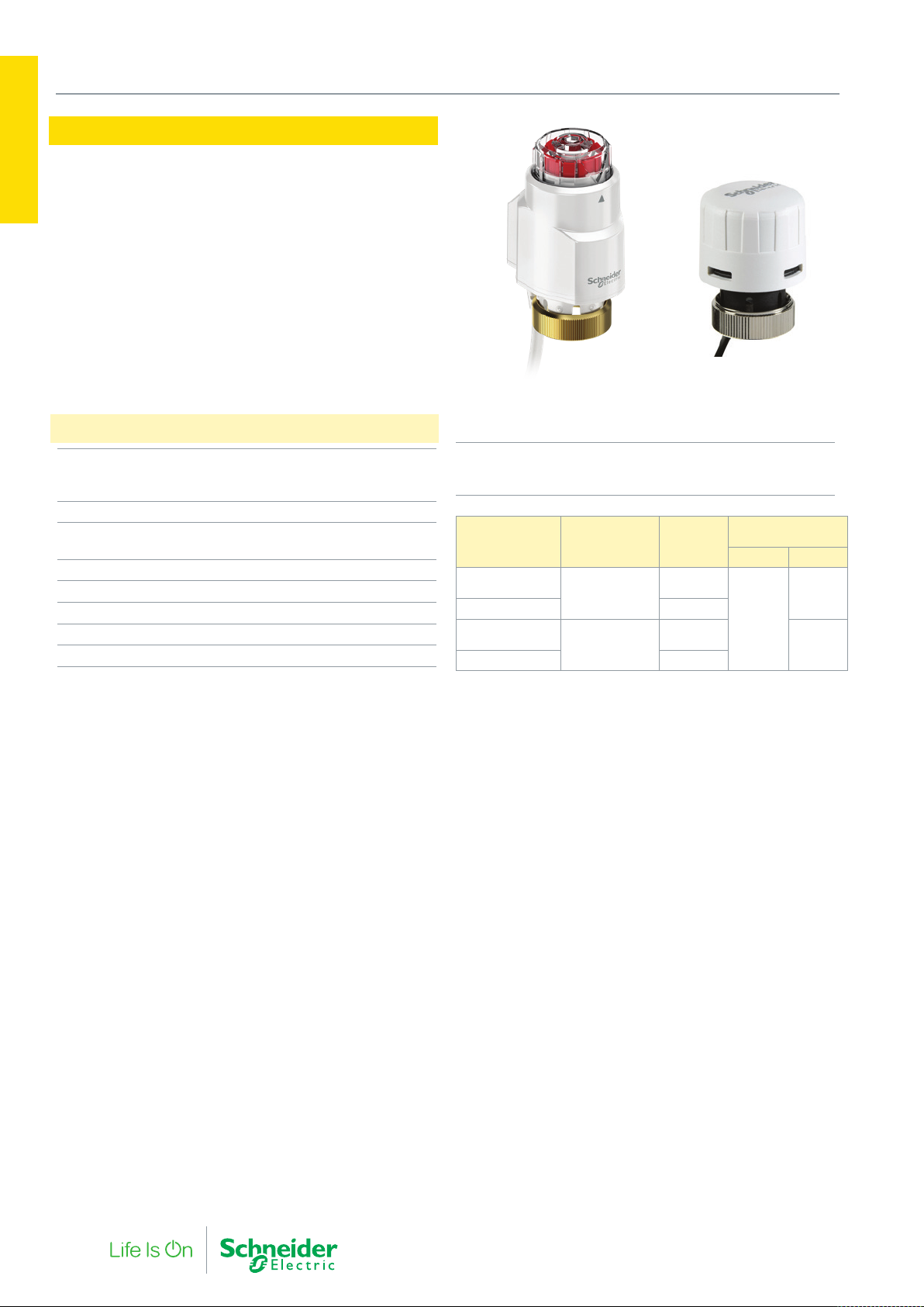
MP120NC and MP140NO are small thermoelectric valve actuators
1. PIBCV Valves and
in zone applications for two-point and pulse-width-modulated (PWM)
regulation of the SmartX PIBCV valves, from DN10…DN32. The
MP120 has a manual override operation for easy flushing.
• Water-protected housing design in all mounting positions
• Pluggable cable for easy installation and servicing
• Low power consumption – allowing many actuators to be
driven from the same controller
• Visual indicator showing valve position and type of action
(NO or NC)
Specifications
Power supply
MP120xx-24T:
MP120xx-230T:
Power consumption 2 W
Environment
Operating Temperature
Protection standard IP44 in all mounting positions
Cable length (standard) 1.5 m
Cable size 2 x 0.5 mm
Medium temperature Max. 120 °C
Valve connection M30 x 1.5
24 Vac/Vdc ± 20%
230 Vac + 10%…15%
Max. 50 °C
MP120 NC MP140 NO
Stroke Range
MP120NC
MP140NO
Part
Number
MP120NC-24T
MP120NC-230T 230 Vac
2
MP140NO-24T
MP140NO-230T 230 Vac
Action Voltage
Normally Closed
(Stem Down)
Normally open
(Stem Up)
MP140NO is limited to 80% of Q
nom
on VP229E
24 Vac/
Vdc
24 Vac/
Vdc
8 mm
4 mm
Operational Flow
Range
VP228E VP229E
20110%
20-120%
20-80%
12 F-27878-6
Page 13
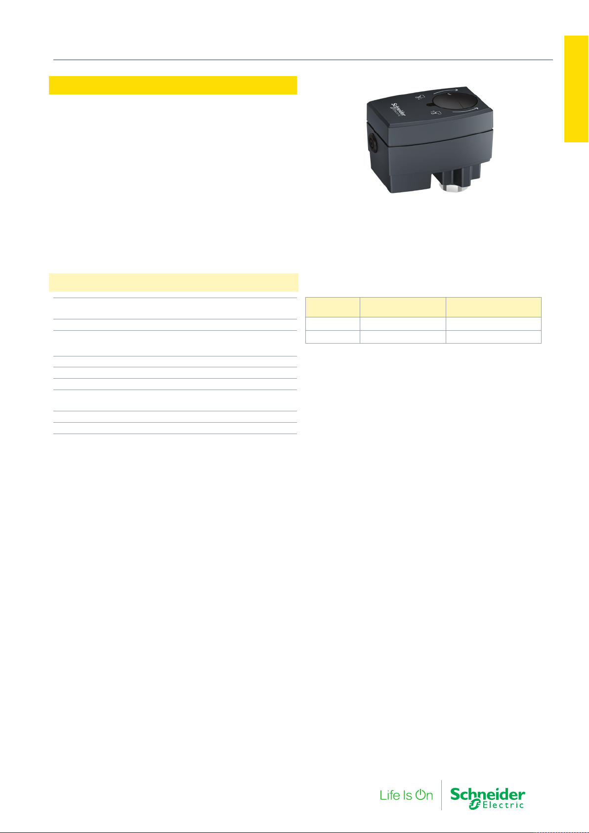
MP300-SR
1. PIBCV Valves and Actuators
Actuators
MP300-SR actuators with Floating and Proportional control are
low voltage motoric actuators for the Smart X PIBCV DN10-32
Valves. These actuators have a spring return safety function that
provides for an open or close valve in the event of power loss.
The Spring return safety function should not be used for twoposition control.
Specifications
Power supply
Frequency
Power consumption 9 VA
Control input Y 0…10 (2…10) V
Output signal U 0…10 (2…10) V
Speed 11.75 (50 hz) s/mm
Max. medium temperature 120 °C
Environment
Operating Temperature
Enclosure rating IP 54
Weight 0.8 kg
24 V; +10…–15 %; AC
50/60 Hz
0…20 (4…20) mA
0…55 °C
Part Number
MP300-SRU Up - Normally Open Adapter
MP300-SRD Down - Normally Closed Spacer
Spring Return
Direction
Linkage type
(included with actuator)
1. PIBCV Valves and
F-27878-6 13
Page 14
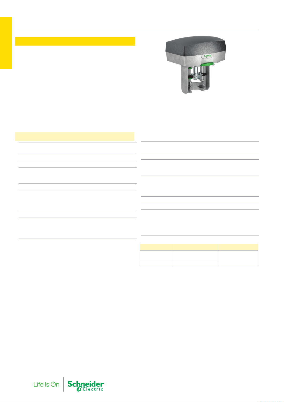
1. PIBCV Valves and Actuators
MP500C
Actuators
MP500C linear electro-mechanical actuator for the control of the
1. PIBCV Valves and
VP220 SmartX PIBCV, DN40…100.
MP500C is controls either by an increase/decrease floating signal
or by a range of modulating control signals between the span of
0…10 V.
• High resolution control for precise fluid control.
• Working range and end point switches calibrate to any stroke
and flow setting of the valve.
• Fixed proportional running time of 15s regardless of valve
stroke.
Specifications
Supply Voltage 24 Vac +/- 10%, 50…60Hz 24
Power consumption average 15 VA
Transformer sizing 50 VA
Running time
Modulating
Increase/decrease
Duty cycle max. 20%/60 minutes
Analog input (Y-M)
Voltage Range
Selectable Input signals
Impedance minimum 100 k Ohm
Digital input (Y2-Y1)
Voltage across open input
Current through closed input
Minimum Pulse time
2…10 V, 0…5 V, 2…6 V,
Vdc +/- 15%
15 s
300 s/60 s
0…10 Vdc
5…10 V, 6…10 V
24 Vac
5 mA
20 ms
• Multi-signal control for either 3-point increase/decrease signal
or various modulating control signals including sequencing.
• Stroke Indicators on the yoke provide clear visual indication to
the valves opening position.
Output U (Position Feedback
Signal)
Load 2 mA
Wiring Entry
Conduit connection
Cable gland
Environment
Operating Temperature
Storage temperature
Humidity
Enclosure rating IP 54 (NEMA 2)
Sound power level max. 32 dBA
Material
Housing
Cover
Color
Weight
max. 90% RH non-condensing
2 x M20 knockout
1 x 6..12 mm O/D
–10…+50 °C
–25…+65 °C
Aluminium
ABS/PC plastic
aluminium/grey
1.8 kg (3.96 lb.)
2…10 V
Part Number Description SmartX Valve
MP500C Forta Multi-signal control
880 0104 000 S2 (Aux End Switch)
14 F-27878-6
actuator
DN40-100
Page 15
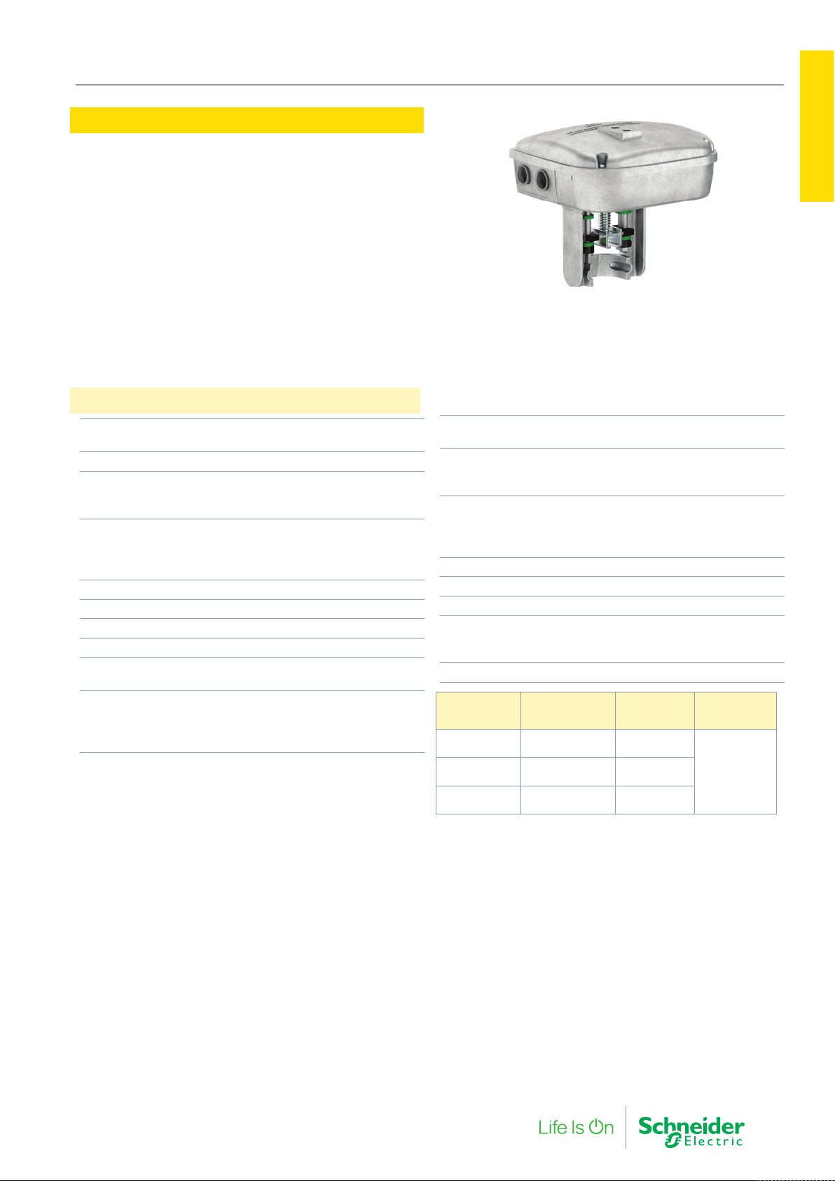
MP500C-SR
1. PIBCV Valves and Actuators
Actuators
The MP500C-SR is spring return linear electro-mechanical actuator
for the control of the VP220 SmartX PIBCV, DN40-100.
• Universal control input and self calibrating to any valve
setting.
• High resolution control board allows precise fluid control.
• Working range and end point switches calibrate to any stroke
and flow setting of the valve.
• A proportional set running time of 15s regardless of valve
stroke.
• Stroke Indicators on the yoke provide clear visual indication to
the valves opening position.
Specifications
MP500C-SRU
MP500C-SRD
Voltage supply 24 Vac ±10% 50-60Hz
Power consumption
Running
Rest
Running Time
Modulating
Increase/decrease
Spring return
Transformer Sizing 50 VA
Stroke Range 2…35 mm
Force, nominal 500 N
Analog input Voltage range 0…10 Vdc
Selectable input signals 0…10, 2…10, 0…5, 2…6,
Digital inputs, Y1, Y2
Voltage across open input
Current through closed input
Minimum Pulse time
Stem up (retract)
Stem down (extend)
30 VA (21 W)
7 W
15 sec.
60/300 sec. (selectable)
13 sec.
5…10, 6…10 Vdc
24 Vac
5 mA
20 ms
Output, Y (Feedback) 2…10 Vdc or 0…5 Vdc (0-100%)
Wiring Entry
Conduit connection
Cable gland
Environment
Operating and Storage
Temperature
Humidity
Enclosure rating IP54
Sound power lever 43 dBa
Max cable core diameter 2.5 mm²
S2 Auxillary Switch Relay
(optional accessory)
Weight 2.8 Kg
Part
Number
MP500C-SRU Spring return
MP500C-SRD Spring return
880 0104 000 S2 auxiliary end
Description
(stem up)
(stem down)
point switches
SPDT, 24 Vac 4A AC1 (contacts
Function on
Power Failure
4 x M20 capped holes
1 x 6..12 mm O/D, IP68
made at 5% and 95% of end
SmartX
Valve
Valve
Open
Valve
Closed
DN40…100
1. PIBCV Valves and
- Load 2 mA
-10 / +50 °C
max 90% RH
stroke)
F-27878-6 15
Page 16
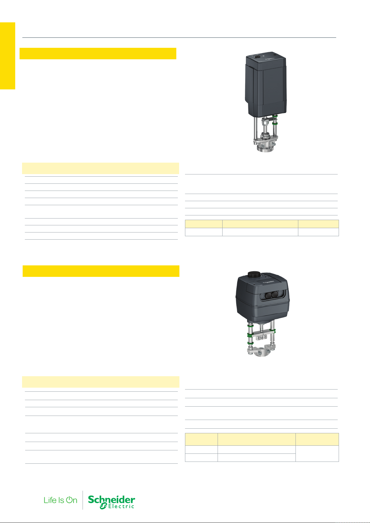
1. PIBCV Valves and Actuators
MP2000
Actuators
1. PIBCV Valves and
Specifications
MP2000 actuator is used with pressure independent balancing and
control large valve type SmartX PIBCV DN125 and DN150. The
actuator has universal control inputs and is self-calibrating.
• Over load protected.
• Diagnostic LED for operational data capture and self-stroking
feature.
• Manual override.
Power supply 24 Vac, +10…–15%
Power consumption 9 VA
Frequency 50 / 60 Hz
Control signal input Modulating and 3 Point floating
Control input Y 0…10 V (2…10) Ri = 24 kΩ
0…20 mA (4…20) Ri = 500 Ω
Output signal X 0…10 V (2…10)
Speed 8 s/mm
Max. medium temperature 200 °C
Environment
Operating
Storage / transp. temp
Protection class III safety extra-low voltage
Enclosure rating IP 54
Weight 7.5 kg
Part Number Description SmartX Valve
MP2000 Multi-signal Actuator, Fail in place DN125…150
0…55 °C
–40…+70 °C
MP2000-SR
The MP2000-SR is a spring return actuator used with the
DN125…150 SmartX PIBCV.
The actuator has universal control inputs and is self-calibrating .
• Manual operation mechanical and/or electrical
• Position indication, LED signalization
• Selectable speed 4 or 6 s/mm
• Integrated external switch
• Linear to EQ% Curve Adaptation
• Anti-oscillation function
• 3-point floating or modulating control selection
• Thermal and overload protection
• Precise regulation and fast response on 3-point signal (0.01 s)
Specifications
Nominal voltage 24 Vac/Vdc, 50 Hz/60 Hz
Power consumption 15 VA
Control input signal Modulating or 3-point floating
Control input Y 0…10 V (2…10 V) Ri = 24 kΩ
0…20 mA (4…20 mA) Ri = 500 Ω
Position Feedback U 0…10 V (2…10 V)
Speed (selectable) 4 or 6 s/mm
Environment
Operating Temperature
0…+ 55 °C
Enclosure rating IP 54
Weight 8.6 kg
Safety function
runtime/50 mm stroke
Manual operation Electrical and Mechanical
Part No.
MP2000-SRU Stem UP, retracts (valve open)
MP2000-SRD Stem Down, extends (valve closed)
Spring Return
Direction
SmartX Valve
DN125…150
120 s
16 F-27878-6
Page 17
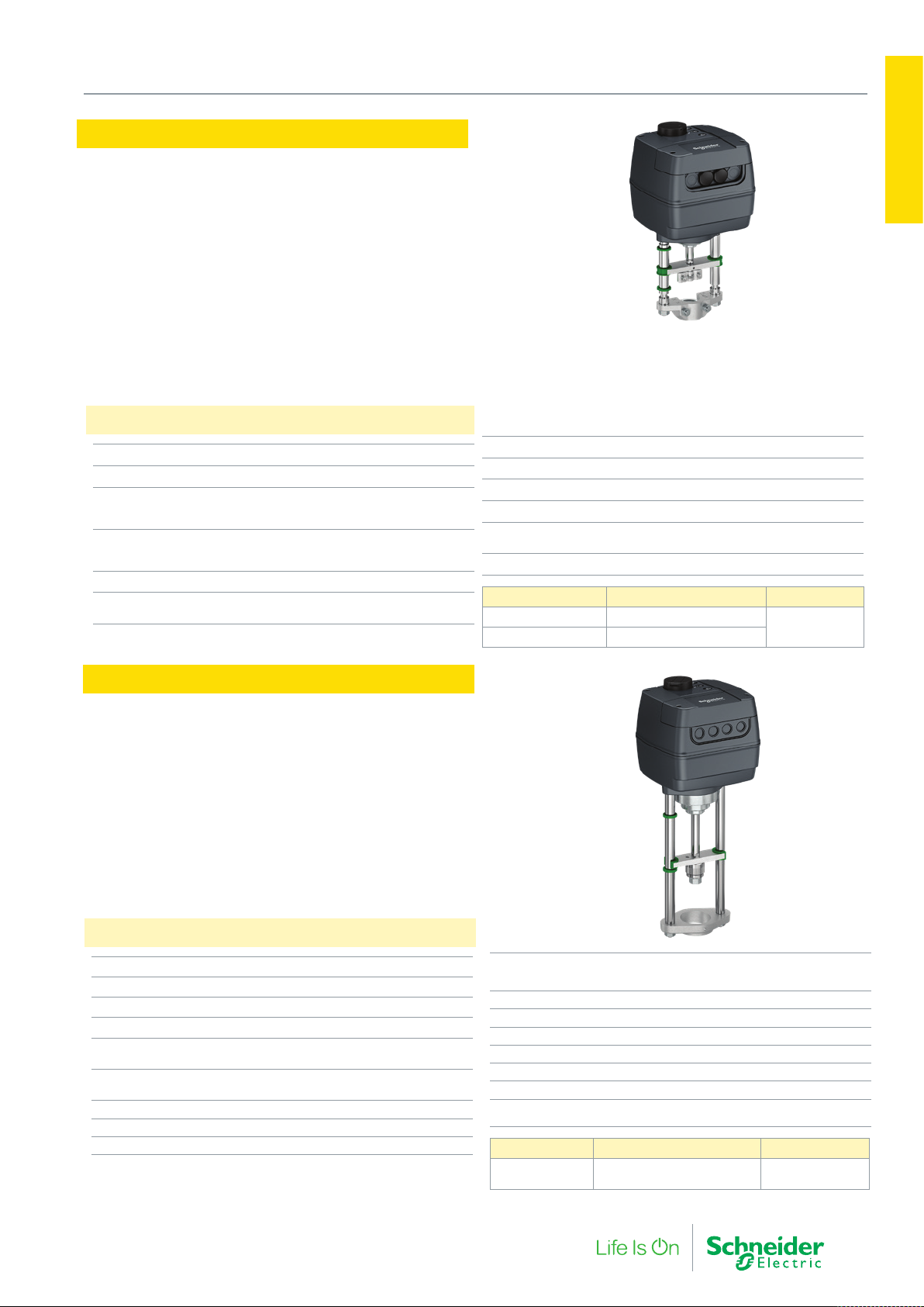
MP2000-SR-230
1. PIBCV Valves and Actuators
Actuators
The MP2000-SR-230 is a line voltage spring return actuator for the
DN125…150 SmartX PIBCV.
The actuator has universal control inputs and is self-calibrating.
• Manual operation mechanical and/or electrical
• Position indication, LED signalization
• Integrated external switch
• 3-point or modulating control selection
Specifications
Nominal voltage 230 Vac, 50 Hz/60 Hz
Control input signal Modulating or 3-point
Control input Y 0…10 Vdc (2…10)
Control output U 0…10 Vdc (2…10)
Speed (selectable) 2 or 6 s/mm
Temperature
Operating
0…20 mA (4…20) 3-point
0…20 mA (4…20)
0…+ 55 °C
Humidity 5…95%
Enclosure rating IP 54
Power consumption 35.7 VA
Weight 8.6 Kg
Safety function
runtime/50 mm stroke
Manual operation Electrical and Mechanical
Part Number Description SmartX Valve
MP2000-SRU-230 Stem Up (Valve Open)
MP2000-SRD-230 Stem Down (Valve Closed)
DN125…DN150
1. PIBCV Valves and
120 s.
MP4000
The MP4000 is a powerful universal control actuator for the DN200
and DN250 Smart X PIBCV.
• Universal input control and self-calibrating.
• Manual operation mechanical and/or electrical
• Position indication, LED signalization
• Integrated external switch
• Characteristic optimization
• 3-point floating or modulating control selection
• Thermic and overload protection
• Precise regulation and fast response on 3-point signal (0.01 s)
Specifications
Power supply 24 Vac/Vdc (+10, -15%)
Power consumption 15 VA
Signal 10 mA
Frequency 50/60 Hz
Control input Y
Control output U
Speed (selectable) 3 s/mm or 6 s/mm
Max. spindle travel 80 mm
Max. medium temperature 200 °C
0…10 Vdc (2…10 Vdc); 0…20
0…10 Vdc (2…10 Vdc); 0…20
mA (4…20 mA)
mA (4…20 mA)
Environment
Ambient Temperature
Storage / transport Temperature
Humidity
Protection class II
Enclosure rating IP 54, Type 2
Electrical connection conduit
Weight 7.5 Kg
Manual operation Electrical and mechanical
Power failure response Stem remains in last
Part Number Description SmartX Valve
MP4000 Multi-signal control, Fail in
place
0…+ 55 °C
−40…+70 °C
DN200-250
5…95%
position
F-27878-6 17
Page 18

and Acuators
2. Zone Valves
18 F-27878-6
Page 19

2. Zone Valves and Actuators
Zone valves provide hydronic flow control in terminal units such
as fan coils. A comprehensive range of products is provided with
a large selection of capacities, connection types and choice in
electrical actuator control.
and Acuators
2. Zone Valves
F-27878-6 19
Page 20
2. Zone Valves and Actuators
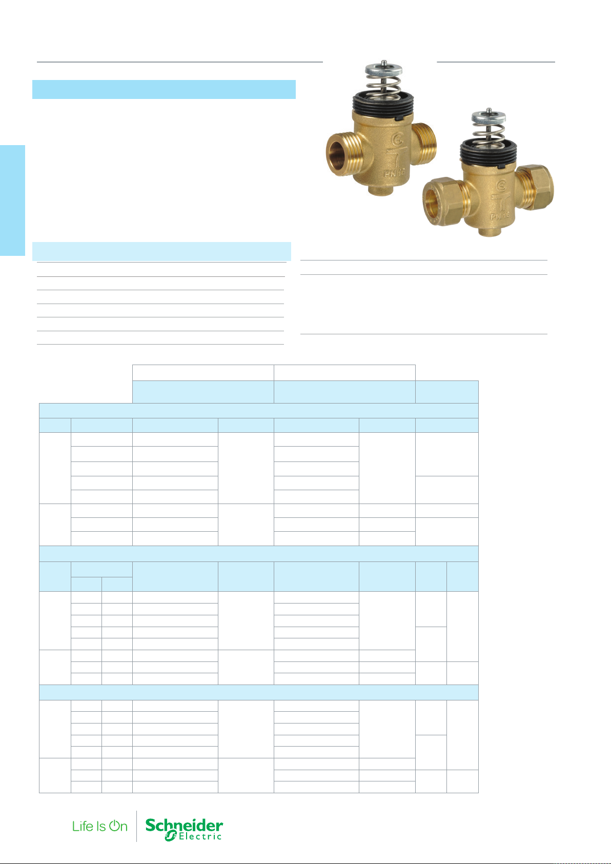
VZ*08*
The VZ*08* short stroke (2.5 mm) zone valves are small linear valves
designed for control of hot and chilled water in fan coils or other
terminal unit applications.
These particular valves are designed to be used with
thermo-electric actuators type MZ140, which is available in an on/off
or a modulating variant.
and Acuators
2. Zone Valves
Specifications
Valve types 2-way, 3-way, 3-way with bypass
Pressure class PN16
Stroke 2.5 mm
Max fluid speed 3 m/s
Media Water, water+glycol (30% max)
Leakage 0% tight close-off
Main Construction Materials
Valve body Brass (CW617N)
Trim Glass reinforced PPS
Stem Stainless steel (AISI 303)
Stem packing Double EPDM O-ring
Plug sealing EPDM
VZ*08E VZ*08C
Temperature Range 5…95 °C
VZ*08E VZ*08C
Flat face Compression*
2-way valves
Size Kvs Part Number Connection Part Number Connection A-AB
0.25 VZ208E-15BP01
0.4 VZ208E-15BP02 VZ208C-15BP02
DN15
DN20
3-way valves
DN15
DN20
3-way valves with integral by-pass (4 ports)
DN15
DN20
* Nuts and Olives supplied with Valve
0.6 VZ208E-15BP03 VZ208C-15BP03
1 VZ208E-15BP04 VZ208C-15BP04
1.6 VZ208E-15BP05 VZ208C-15BP05
2.5 VZ208E-20BP07
4 VZ208E-20BP08
6 VZ208E-20BP09
Kvs
A-AB B-AB
0.25 0.25 VZ308E-15BP01
0.4 0.4 VZ308E-15BP02 VZ308C-15BP02
0.6 0.6 VZ308E-15BP03 VZ308C-15BP03
1 0.8 VZ308E-15BP04 VZ308C-15BP04
2.5 1.6 VZ308E-20BP07
4 2.5 VZ308E-20BP08
6 4 VZ308E-20BP09
0.25 0.25 VZ408E-15BP01
0.4 0.4 VZ408E-15BP02 VZ408C-15BP02
0.6 0.6 VZ408E-15BP03 VZ408C-15BP03
1 0.8 VZ408E-15BP04 VZ408C-15BP04
2.5 1.6 VZ408E-20BP07
4 2.5 VZ408E-20BP08
6 4 VZ408E-20BP09
Part Number Connection Part Number Connection A-AB B-AB
G1/2A
G3/4A
G1/2A
G3/4A
G1/2A
G3/4A
VZ208C-15BP01
15 mm
VZ208C-20BP07 22 mm 250
VZ308C-15BP01
15 mm
VZ308C-20BP07 22 mm
VZ408C-15BP01
15 mm
VZ408C-20BP07 22 mm
Max Close-off
(kPa) MZ140
400
350
150
400
400
3501.6 1 VZ308E-15BP05 VZ308C-15BP05
100 40
400
400
3501.6 1 VZ408E-15BP05 VZ408C-15BP05
100 40
20 F-27878-6
Page 21
MZ140
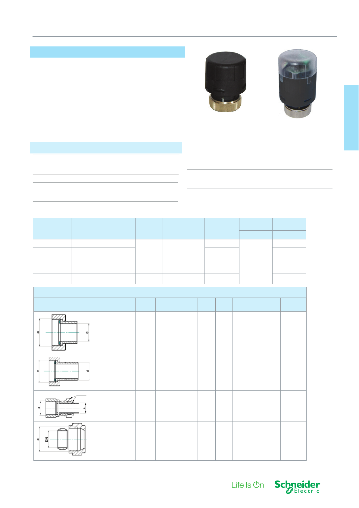
MZ140 thermo-electric actuators are wax filled actuators that are
silent in operation, providing either on/off or modulating control for
the VZ*08* zone valves.
2. Zone Valves and Actuators
Specifications
Environment
Operating Temperature 2…50 °C
Storage Temperature -10…60 °C
Stem force 140N
Max stroke
MZ140-24T / 230T 4 mm
MZ140-24M 2.5 mm
Part Number Full Type Designation
MZ140-230T MZ140-110/230T 2M44 00
MZ140-24T MZ140-24T 2M44 00
MZ140-24T-5M MZ140-24T 5M44 00 5m
MZ140-24T-10M MZ140-24T 10M44 00 10m
MZ140-24M MZ140-24M 2M44 00 2m
Connections for VZ*08 Series Zone Valves
Connection
type
Cable
Length
2m
Pipe
size
Control signal Power
On/Off
0…10 V modulating
DN a
MZ140-24T MZ140-24M
Coupling ring M30 x 1.5
Power cable 2m bipolar (0.75 mm2)
Main Construction Materials
Fire-resistant case Class V0
Protection class IP 44 (for vertical mounting)
Power
consumption
VA A
110-230 Vac
24 Vac/Vdc 0.17
24 Vac 0.2
c
d e Part Number
(mm)
1.8
Initial
consumption
0.25
Pack
quantity
and Acuators
2. Zone Valves
*One fitting required per valve port.
Flat Face External thread
to Solder *
External
Thread
Flat face external thread to
compression*
Compression
Capnut and
olive
12 mm
15 mm
R 3/8”
R 1/2”
15 mm
22 mm
15 mm
20 mm
15 20G 1/2
G 3/4
15 20G 1/2
G 3/4
15 20G 1/2
G 3/4
G1/2A
15
Whitworth
20
1 1/8” - 14
12
15
-
- -
- -
- -
R 3/8
-
R 1/2
15 22911 2080 000
15 22911 2082 000
911 2076 000
911 2077 000
911 2078 010
911 2079 010
911 2081 000
911 2083 000
1
10
1
10
F-27878-6 21
Page 22
2. Zone Valves and Actuators
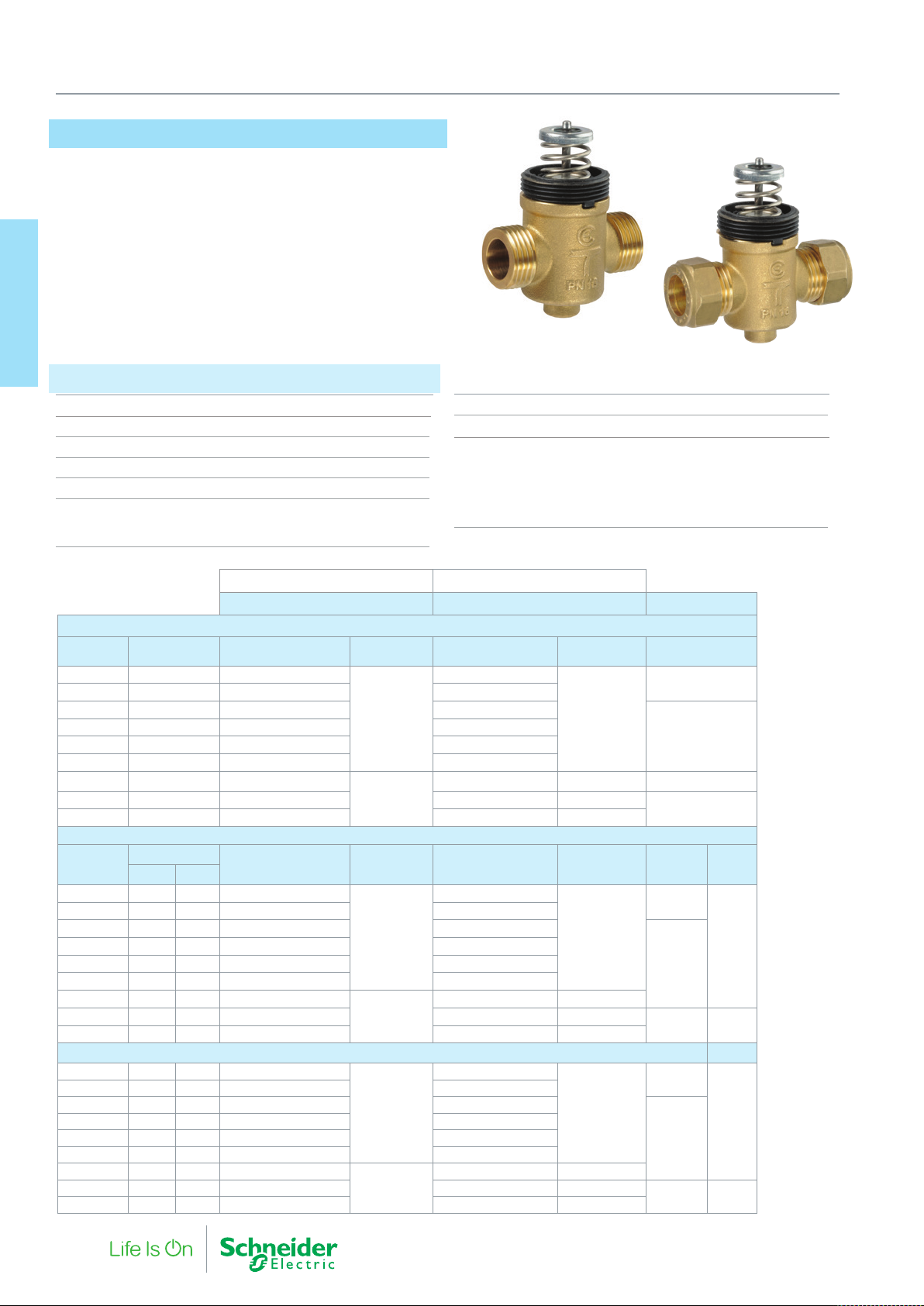
VZ*19*
These long stroke (5.5 mm) small linear zone valves are designed
for the regulation in flow of hot and chilled water in fan coils or other
terminal unit applications.
These particular valves are designed to be used with the compact
electro-mechanical actuators type MZ20.
and Acuators
2. Zone Valves
Specifications
Pressure class PN16
Stroke 5.5 mm
Max fluid speed 3 m/s
Media temperature range 2…95 °C
Max. Glycol concentration 30%
Flow Characteristics
On direct (A-AB) way Equal percentage
On by-pass (B-AB) way Linear
VZ*19E VZ*19C
Leakage 0% tight close-off
Rangeability 50:1
Main Construction Materials
Valve body Brass (CW617N)
Trim Glass reinforced PPE
Stem Stainless steel (AISI 303)
Stem packing Double EPDM O-ring
Plug sealing EPDM
VZ*19E VZ*19C
Flat face external thread Compression End Connection*
2-way valves
Size Kv Part Number Connection Part Number Connection A-AB
DN15 0.25 VZ219E-15BP01
DN15 0.4 VZ219E-15BP02 VZ219C-15BP02
DN15 0.6 VZ219E-15BP03 VZ219C-15BP03
DN15 1 VZ219E-15BP04 VZ219C-15BP04
DN15 1.6 VZ219E-15BP05 VZ219C-15BP05
DN15 2 VZ219E-15BP06 VZ219C-15BP06
DN20 2.5 VZ219E-20BP07
DN20 4 VZ219E-20BP08
DN20 6 VZ219E-20BP09
3-way valves
Kvs
A-AB B-AB
DN15 0.25 0.25 VZ319E-15BP01
DN15 0.4 0.25 VZ319E-15BP02 VZ319C-15BP02
DN15 0.6 0.4 VZ319E-15BP03 VZ319C-15BP03
DN15 1 0.6 VZ319E-15BP04 VZ319C-15BP04
DN15 1.6 1 VZ319E-15BP05 VZ319C-15BP05
DN15 2 1.6 VZ319E-15BP06 VZ319C-15BP06
DN20 2.5 1.6 VZ319E-20BP07
DN20 4 VZ319E-20BP08
DN20 6 VZ319E-20BP09
3-way valves with integral by-pass (4 ports)
DN15 0.25 0.25 VZ419E-15BP01
DN15 0.4 0.25 VZ419E-15BP02 VZ419C-15BP02
DN15 0.6 0.4 VZ419E-15BP03 VZ419C-15BP03
DN15 1 0.6 VZ419E-15BP04 VZ419C-15BP04
DN15 1.6 1 VZ419E-15BP05 VZ419C-15BP05
DN15 2 1.6 VZ419E-15BP06 VZ419C-15BP06
DN20 2.5 1.6 VZ419E-20BP07
DN20 4 VZ419E-20BP08
DN20 6 VZ419E-20BP09
Nuts and olives supplied with the compression end connection valve
Part Number Connection Par t Number Connection A-AB B-AB
G1/2A
G3/4A
G1/2A
G3/4A
G1/2A
G3/4A
VZ219C-15BP01
15 mm
VZ219C-20BP07 22 mm 250
VZ319C-15BP01
15 mm
VZ319C-20BP07 22 mm
VZ419C-15BP01
15 mm
VZ419C-20BP07 22 mm
Max Close-off
(kPa) MZ20
400
350
150
400
350
100 40
400
350
100 40
400
400
22 F-27878-6
Page 23
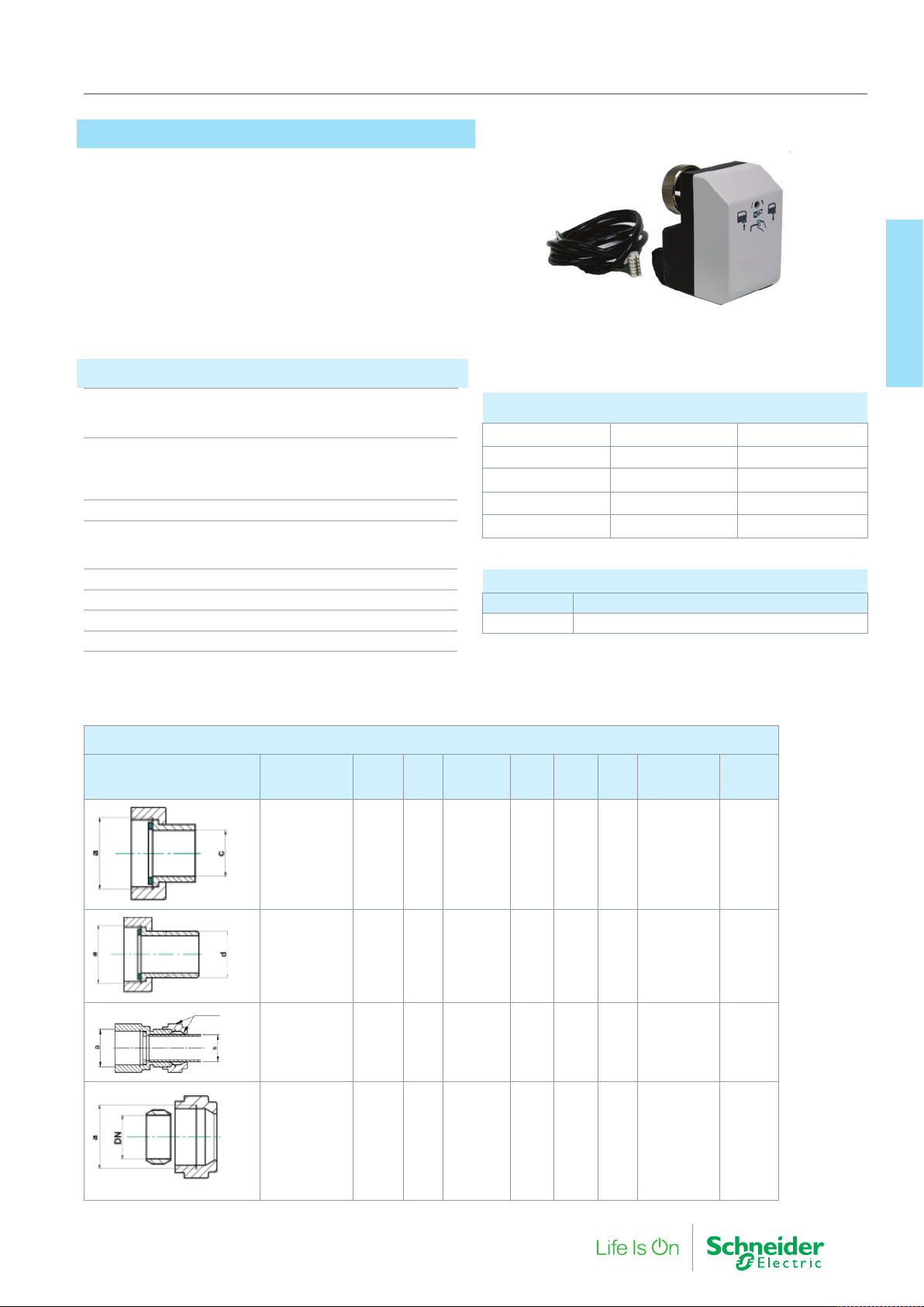
MZ20
The long stroke MZ20 is an electro-mechanical zone valve actuator
designed for use with the VZ*19* valves.
The actuator provides precise valve position and flow for good
hydronic control.
Reliable long term operation is provided by the optimal design without feedback potentiometer or end switches.
Specifications
Input voltage
MZ20A 24 Vac, 50/60 Hz
MZ20B 24 Vac or 230 Vac 50/60 Hz
Power consumption
MZ20A 1 VA
MZ20B-24 0.7 VA
MZ20B-230 5 VA
Speed 18 s/mm (50 Hz)…15 s/mm (60 Hz)
Temperature
Working -5…+55 °C
Storage -25…+65 °C
Stem force 200 N
Max stroke 5.5 mm
Connection cable 3 wires 1.5 m
Protection class IP 43 (for vertical mounting)
2. Zone Valves and Actuators
MZ20A/B zone valve actuator for VZ*19 valves
Part Number Description Control
845 5051 000 MZ20A Selectable*
845 5052 000 MZ20A-R 0…10 V
845 5001 000 MZ20B-24 3P-24 Vac
845 5003 000 MZ20B-230 3P-230 Vac
* 0…10 V, 6…9 V, 1…5 V, 2…10 V, 4…7 V , 6…10 V, 8…11 V
Accessory
Part Number Description
911 6006 000 6m 24V pluggable cable pack, 10 pieces
and Acuators
2. Zone Valves
Connections for VZ*19 Series Zone Valves
Connection
type
Flat Face External thread to
Solder *
External
Thread
Flat face external thread to
compression*
Compression
Capnut and
olive
Pipe
size
12 mm
15 mm
R 3/8”
R 1/2”
15 mm
22 mm
15 mm
20 mm
DN a
15 20G 1/2
G 3/4
15 20G 1/2
G 3/4
15 20G 1/2
G 3/4
G1/2A
15
Whitworth
20
1 1/8” - 14
c
d e Part Number
(mm)
12
- -
15
R 3/8
R 1/2
- -
- -
911 2076 000
911 2077 000
911 2078 010
911 2079 010
15 22911 2080 000
911 2081 000
15 22911 2082 000
911 2083 000
Pack
quantity
1
10
1
10
*One fitting required per valve port.
F-27878-6 23
Page 24
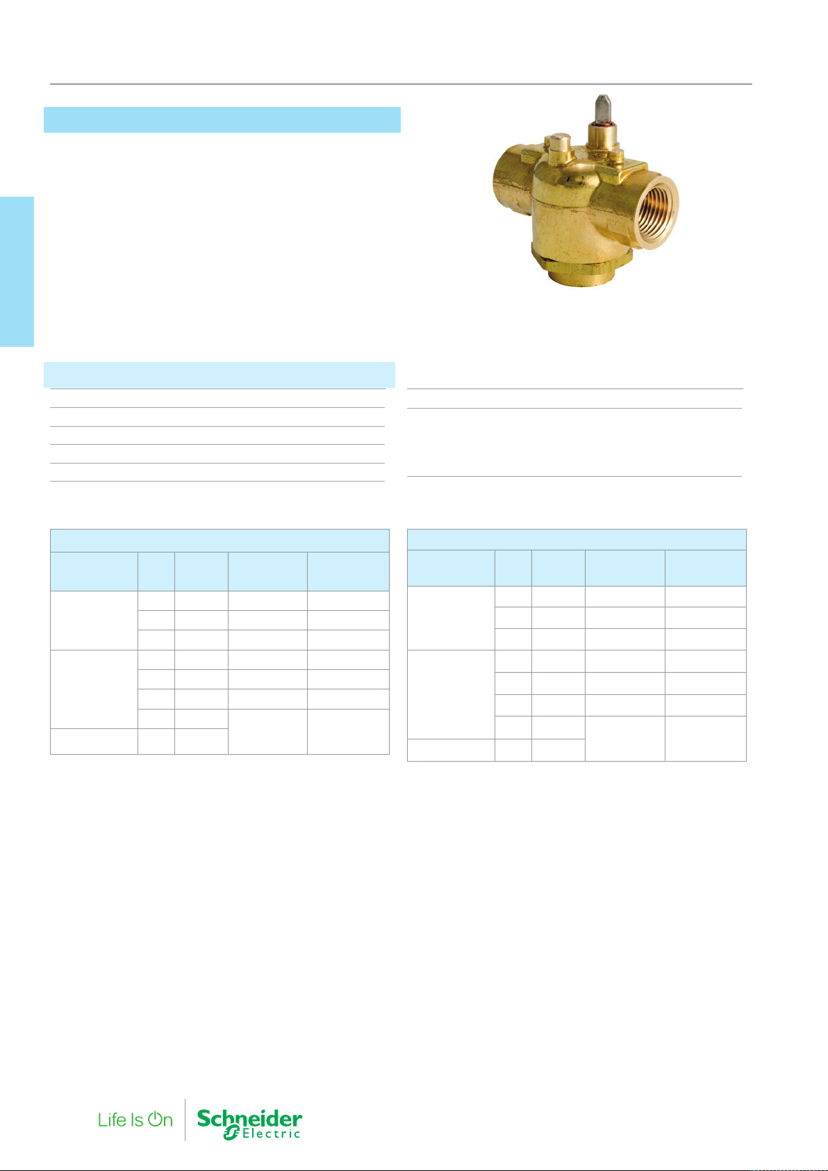
2. Zone Valves and Actuators
Erie VT Zone Valve
The industry leading Erie Zone valve is suitable for on/off control of
hot and chilled water in terminal unit applications.
High flow capacity paddle design and the unique ‘pop-top’ actuator
connection allows for a quick and simple installation.
and Acuators
2. Zone Valves
Specifications
Media Hot and chilled water
Media temperature 0…93 °C
Glycol Concentration 50%
Pressure class 300 psi (PN20)
Seat Leakage 0.01% (ANSI class IV)
∆Pm 100kPa
Main Construction Materials
Valve body Forged Brass
Stem Nickel-plated Brass
Seat Brass
Paddle/ Stem o-rings Buna-N/EPDM
2-way Valves
Thread Kvs
Rp 1/2
Rp 3/4
Rp 1 6.9 VT2437
Part
Number
0.85 VT2231 410 515
2.2 VT2232 275 340
3.0 VT2233 170 205
2.2 VT2332 275 340
3.0 VT2333 170 205
4.3 VT2335 135 170
6.5 VT2337
Max ∆P (kPa)
AG...Actuators
115 135
Max ∆P (kPa)
AH...Actuators
3-way valves
Thread Kvs
Rp 1/2
Rp 3/4
Rp 1 6.9 VT3437
Part
Number
1.3 VT3231 410 515
2.6 VT3232 275 340
3.5 VT3233 170 205
2.6 VT3332 275 340
3.5 VT3333 170 205
4.3 VT3335 135 170
6.5 VT3337
Max ∆P (kPa)
AG...Actuators
115 135
Max ∆P (kPa)
AH...Actuators
24 F-27878-6
Page 25
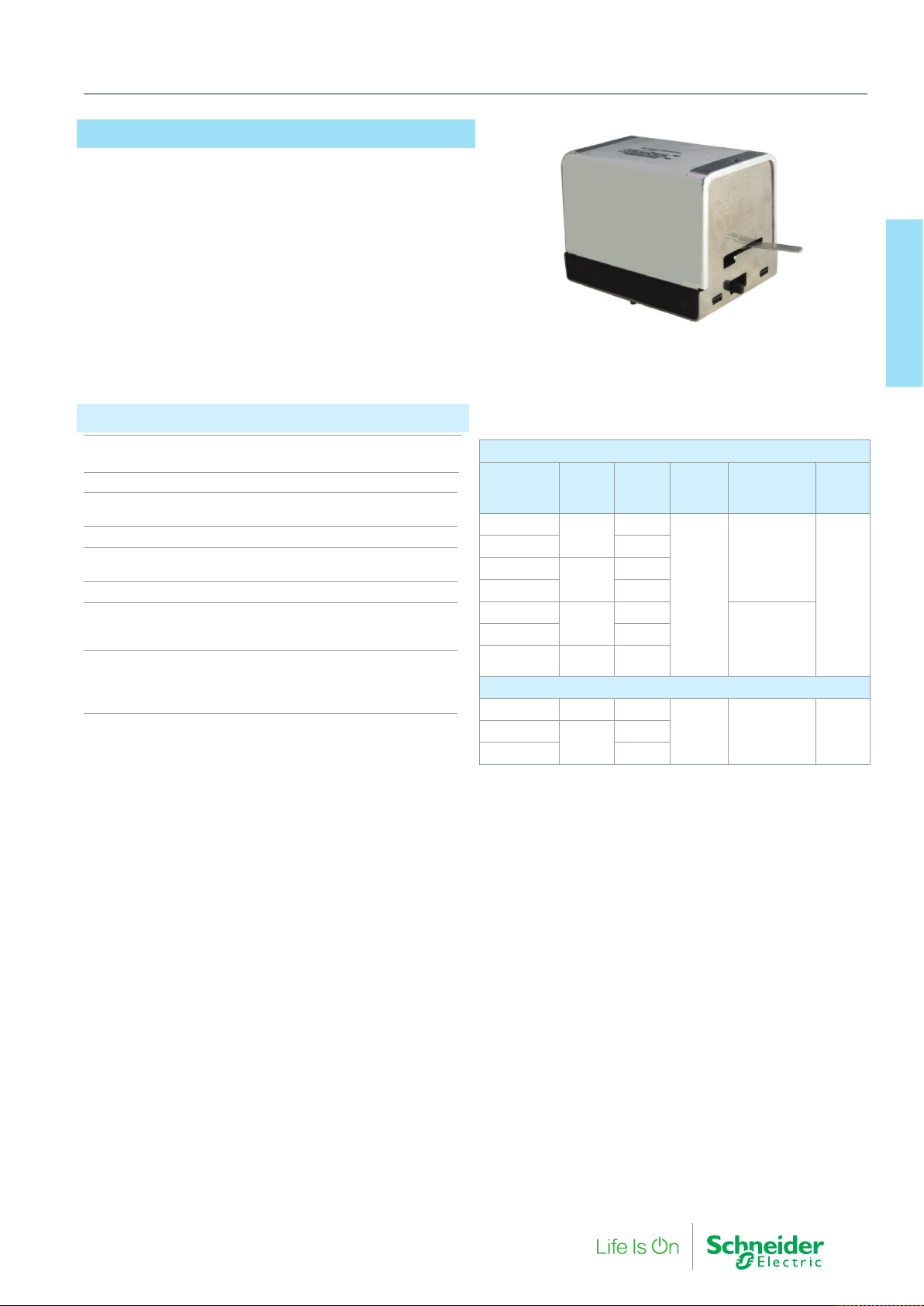
Erie AG/AH Zone Actuator
The AG (General Close Off) and AH (High Close Off)
actuators are spring return, two-position actuators for coupling to the
VT series valves.
The Pop-top connection allows for quick and simple
assembly, all Normally Closed actuators feature a manual override
lever.
Specifications
Supply Voltage 24 Vac @ 50/60 Hz
230 Vac @ 50 Hz
Power Consumption 6.5 watts, 7.5 VA
End Switch 24…240 Vac (101 mA min.…5 A)
9-30 Vdc (100 mA max.)
Control Signal On/Off, 2 position, spring return
Full Running time 30 Sec (50 Hz)
9 Sec (S.R. function)
Enclosure IP31
Main Construction Materials
Base Plate Stainless Steel
Cover Aluminium
Environment
Shipping and Storage -40…71 °C
Operating Temperature 40°
Humidity 5…95% RH, non-condensing
2. Zone Valves and Actuators
General Close-Off Actuator
Part Number Voltage
AG13A230
AG13A23A yes
AG13U230
AG13U23A yes
AG23A230
AG23A23A yes
AG23U230
High Close-Off Actuator
AH13A230 24 Vac -
AH13U230
AH13U23A yes
24 Vac
230
Vac
24 Vac
230
Vac
230
Vac
End
Switch
-
-
-
-
-
Control
On/Off
On/Off
Spring Return
Valve
Function
Normally
Closed
Normally
Open
Normally
Closed
Cable
910
mm
(36”)
910
mm
(36”)
and Acuators
2. Zone Valves
F-27878-6 25
Page 26

Actuators
3. Radiator Valve
26 F-27878-6
Page 27
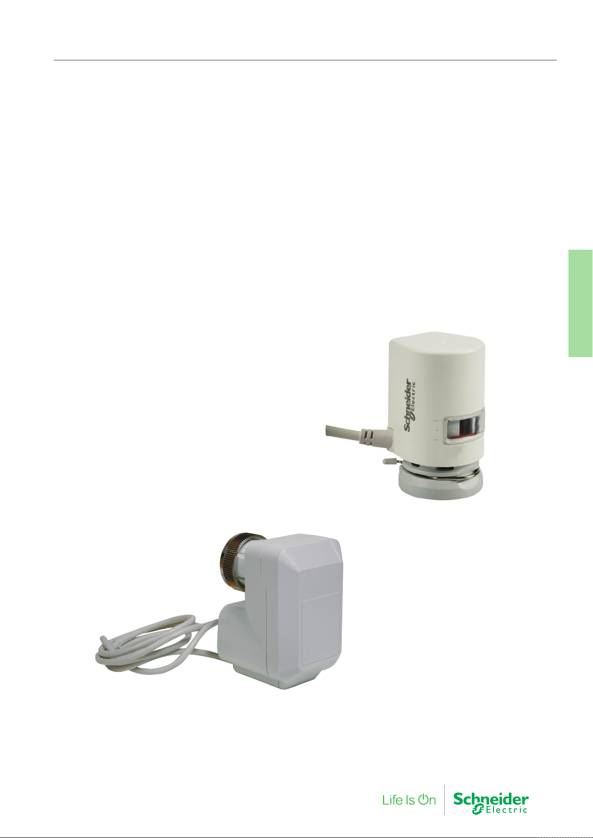
3. Radiator Valve Actuators
Our selection of short stroke valve actuators is designed for BMS
automation of fluid control in radiators and under floor heating
manifolds. The Schneider Electric range provides a dependable
discreet design in every variant.
Actuators
3. Radiator Valve
F-27878-6 27
Page 28
3. Radiator Valve Actuators
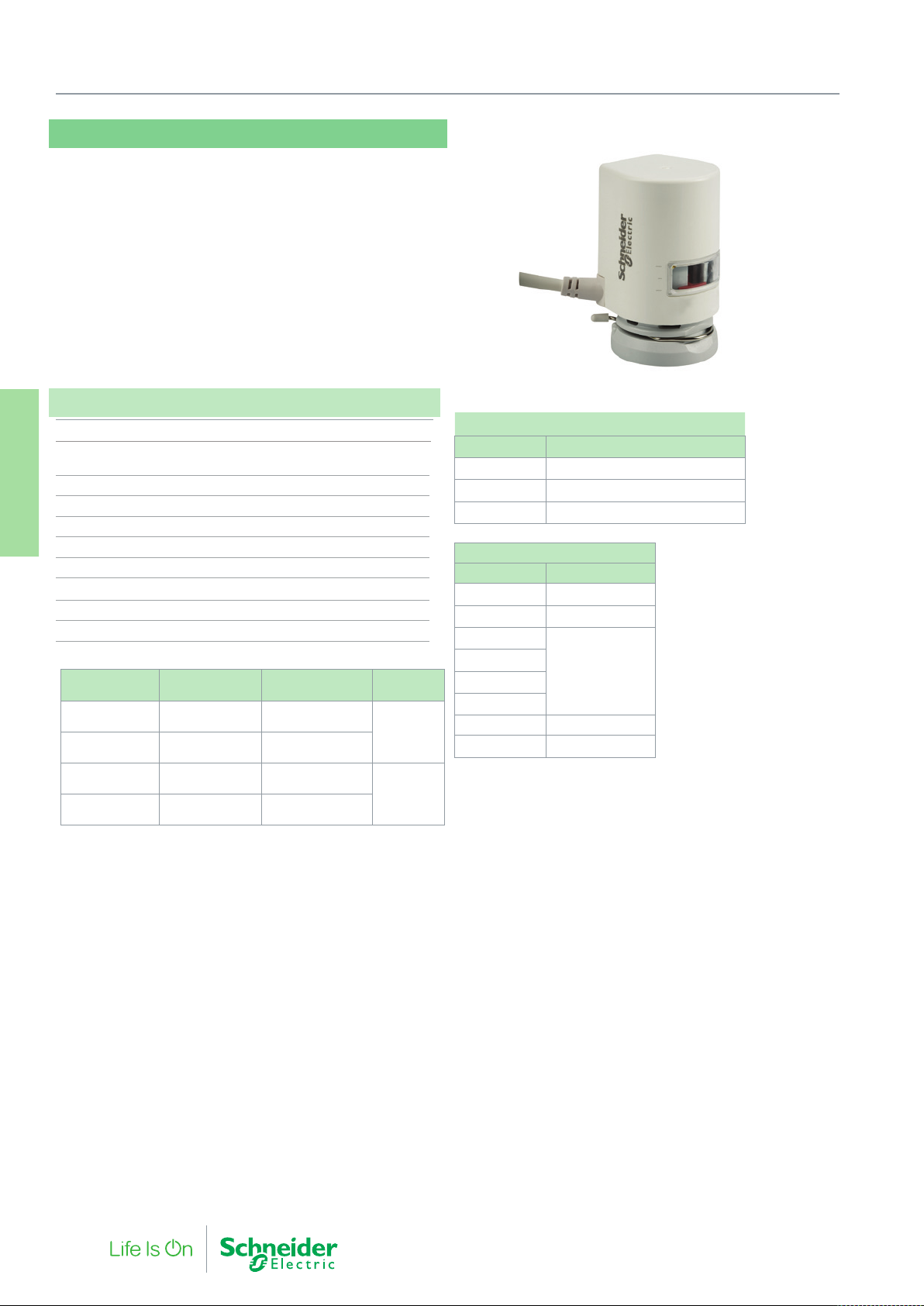
MR95
The MR95 is a small thermoelectric linear radiator valve actuator
used in room applications for time-controlled two-point (On/Off) and
pulse-width-modulated (PWM) regulation
radiators or underfloor heating manifolds.
The MR95 is a discreet design actuator suitable for living space
installations.
Specifications
Max. stroke 4 mm
Supply voltage MR95xx-24T: 24 Vac/Vdc ± 20%
MR95xx-230T: 230 Vac +10%-15%
Stem force 95 N
Actuators
Temperature Range Max. 50 °C
3. Radiator Valve
Power consumption 2 W
Protection standard IP44 in all mounting positions
Cable length (standard) 1.0 m
Cable size 2 x 0.5 mm
Medium temperature Max. 120 °C
Radiator connection M30 x 1.5
Part Number
MR95NC-24T MR95-NCD-24T
MR95NO-24T MR95-NOU-24T
MR95NC-230T MR95-NCD-230T
MR95NO-230T MR95-NOU-230T
1- Without power, in combination with standard radiator valve.
“Normally Closed” = Actuator stem extends downward without power closing the valve,
retracts when powered to open the valve.
“Normally Open” = Actuator stem retracts upward without power opening the valve, extending when powered to close the valve.
Type
Designation
1.0M44 00
1.0M44 00
1.0M44 00
1.0M44 00
1
Action
Normally closed
(stem down)
Normally open
(stem up)
Normally closed
(stem down)
Normally open
(stem up)
Voltage
24 Vac/Vdc
230 Vac
Accessories
Part Number Description
911 4202 500 Additional cable set 2.5M, 10 pcs
911 4205 000 Additional cable set 5M, 10 pcs
911 4210 000 Additional cable set 10M, 10 pcs
Compatible Radiator Valves
Manufacturer Type
2
Drayton
Honeywell
Empur
Heimeier
Junkers
Oventrop
Siemens Duogyr, M30x1.5
TA
2 - Some older TA valves are M28 and not suitable for the MR95.
TRV 4
M30x1.5, all
M30x1.5
2
M30x1.5
28 F-27878-6
Page 29
MZ09L
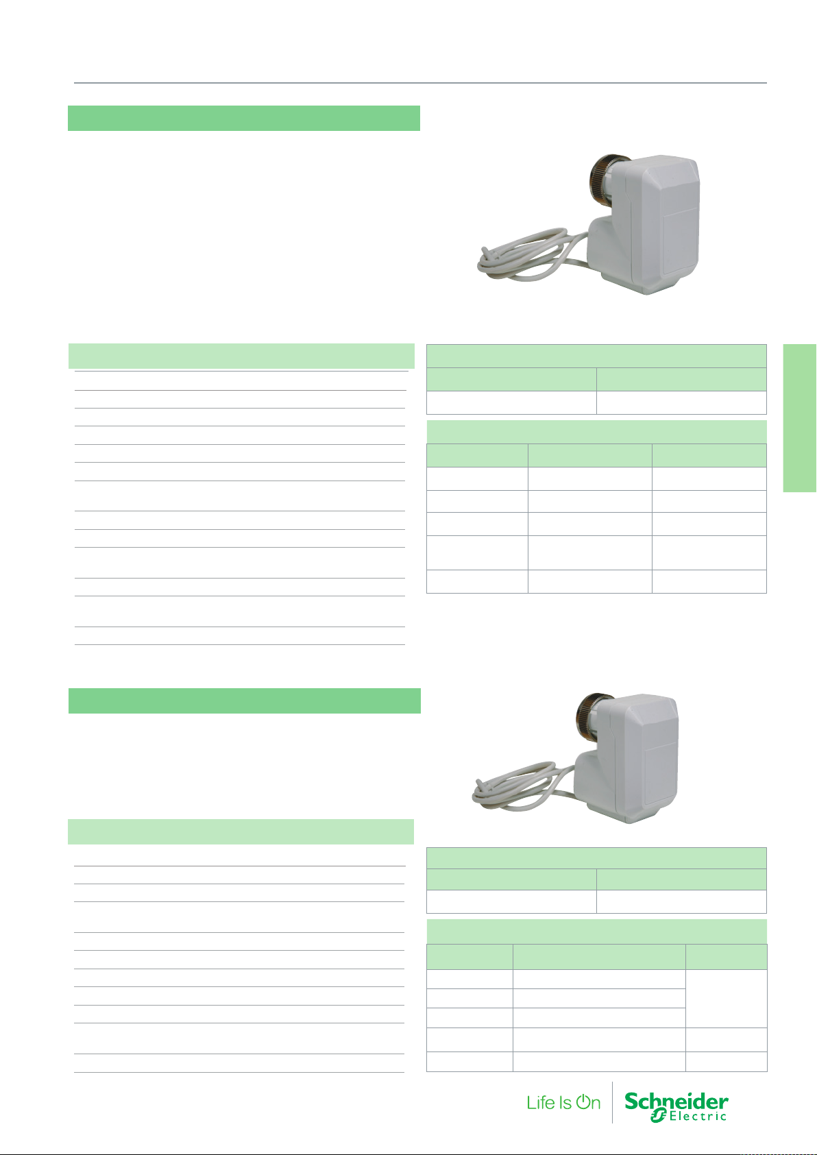
The MZ09L LON® actuator is designed for decentralised building structures and gives customers an effective new capability in
energy management and product flexibility. The actuator works with
standard SNVTs to provide interoperability with controllers based on
LonWorks® technology.
The MZ09L small linear actuator is specifically designed to provide
LonMark® capabilities together with radiator valves and is used in
fan coil units, induction units, small reheaters and recoolers, and for
zone control applications. The MZ09L actuator is suitable for LonWorks technology. Using standard Echelon configuration tools, the
actuator can be configured with job specific settings.
3. Radiator Valve Actuators
Specifications
Power supply 24 Vac, ± 20%, 50/60 Hz
Power consumption 1.4 VA
Control signal SNVT_lev_percent 0…100%
Network protocol LonTalk®
Channel FTT10A
Stroke 2.5 mm
Running time 53s at 50 Hz
44s at 60 Hz
Stem force 90 N (for valves DN15…20)
Insulation class III
Connection cables 1.5 m, three leads
1.5 m, two leads
Coupling ring M 30 x 1.5
Environment
Operating Temperature 0…55 °C
Enclosure rating IP 42
MZ09B
The MZ09B actuator is designed to provide 3-point control together
with radiator valves. The MZ09B actuator is used for radiator valves
in fan coil units, induction units, small reheaters and recoolers, and
for zone control applications. The absence of end switches and
feedback potentiometer provides longtime reliability.
MZ09L actuator for radiator valves
Part Number Description
845 5112 000 MZ 09L(LON) 2.5 mm
Suitable Valves
Manufacturer Valve type Adapter
Honeywell V100, V200 Not required
Heimeier Not required
Siemens L&S Duogyr Not required
Danfoss
Danfoss Series RAVL 911 2074 000
Series RA2000, RA-PN,
RA-N, RA-U, RA-G
911 2075 000
Actuators
3. Radiator Valve
Specifications
Input voltage 24 Vac + 10 % / -30 %; 50/60 Hz
Power consumption 0.7 VA
Control mode Floating (3-point)
Stroke 1.6 mm controlled valve stroke
7.9 mm complete actuator stroke
Running time 36 s / 1.6 mm valve stroke
Stem force 90 N
Protection standard IP 43
Connection cable 0.9 m
Coupling ring M 30 x 1.5
Environment
Operating Temperature 0…60 °C
Enclosure rating IP 42
F-27878-6 29
MZ09B actuator for radiator valves
Part Number Description
845 5111 000 MZ 09B 2.5 mm
Suitable valves
Manufacturer Valve type Adapter
Honeywell V100, V200
Not requiredHeimeier
Siemens L&S Duogyr
Danfoss
Danfoss Series RAVL 911-2074-000
Series RA2000, RA-PN, RA-N, RA-U,
RA-G, RA-UR, RA-KE, RA-K
911-2075-000
Page 30
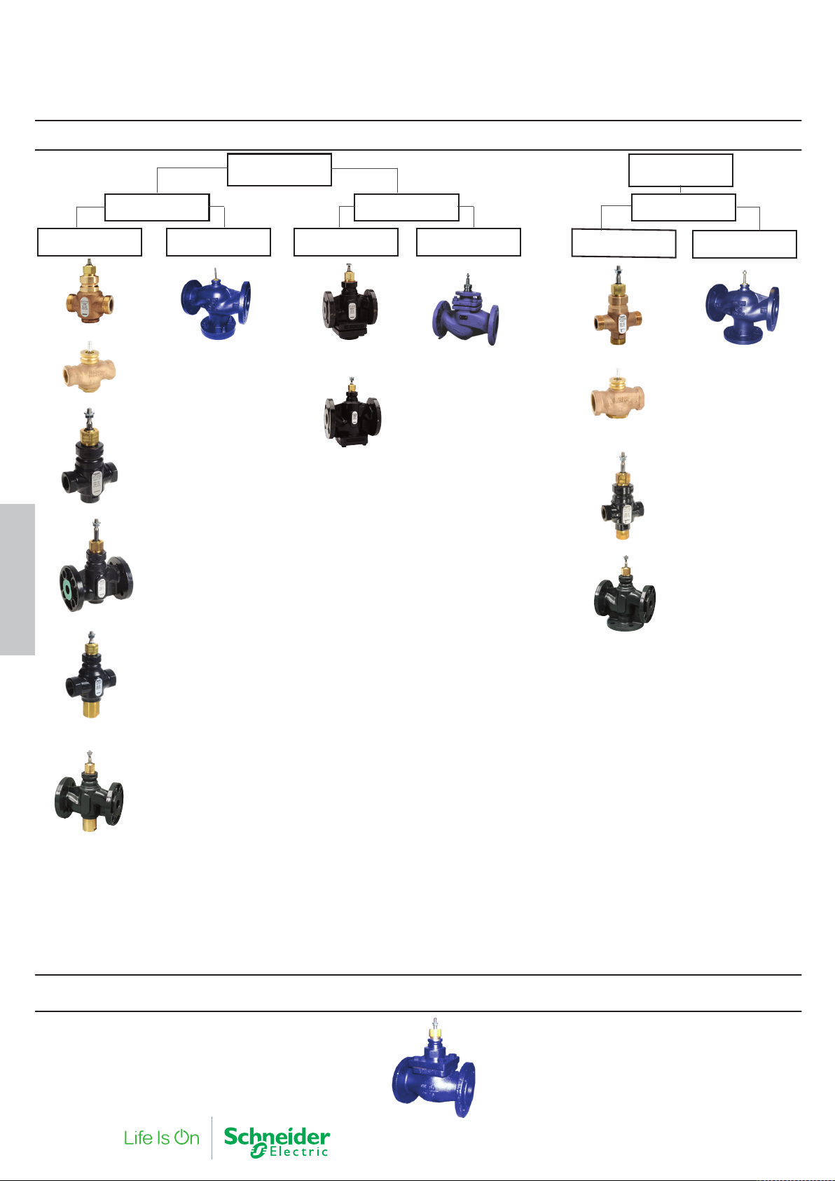
Hot and Chilled Water
DN15-50
V241
VG210R
V211T
PN16
DN65-150
VG221F
2-way
PN25
DN15-50 DN65-150
V231
V232
(balanced)
V292
3-way
PN16
DN15-50 DN65-150
V341
VG310R
V311T
VG311F
4. Globe Valves
V211
V212T
(balanced)
V212
(balanced)
V311
Steam (2-way, 200°C, PN16, DN15-100)
30 F-27878-6
VGS211F
Page 31
4. Globe Valves
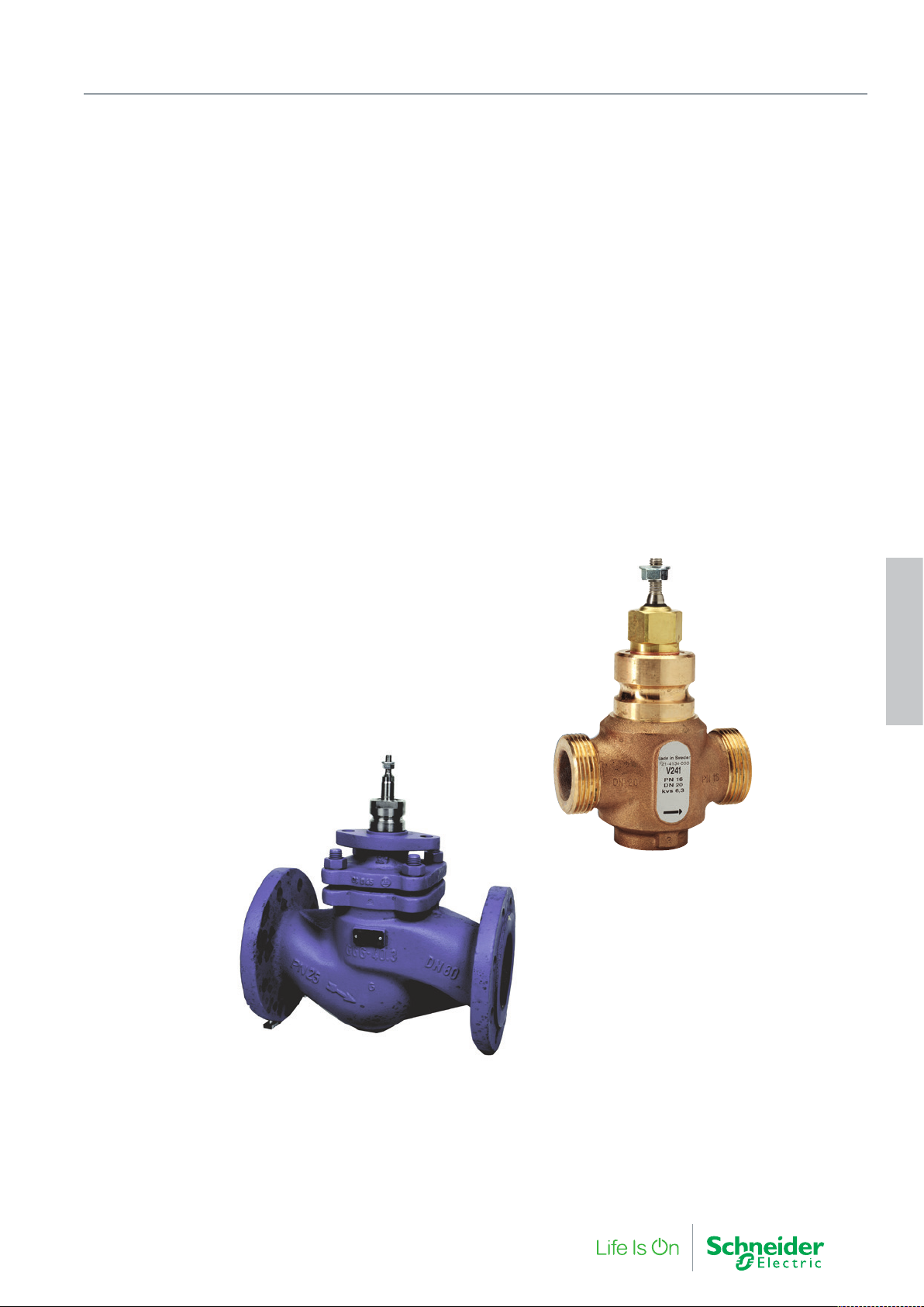
Globe valves provide the finest level of fluid control. The Schneider
Electric portfolio covers an extensive range of products for almost
any working pressure and flow capacity.
Globe valves can be serviced to provide a very long and reliable
working life to any plant they are installed within.
4. Globe Valves
F-27878-6 31
Page 32
4. Globe Valves
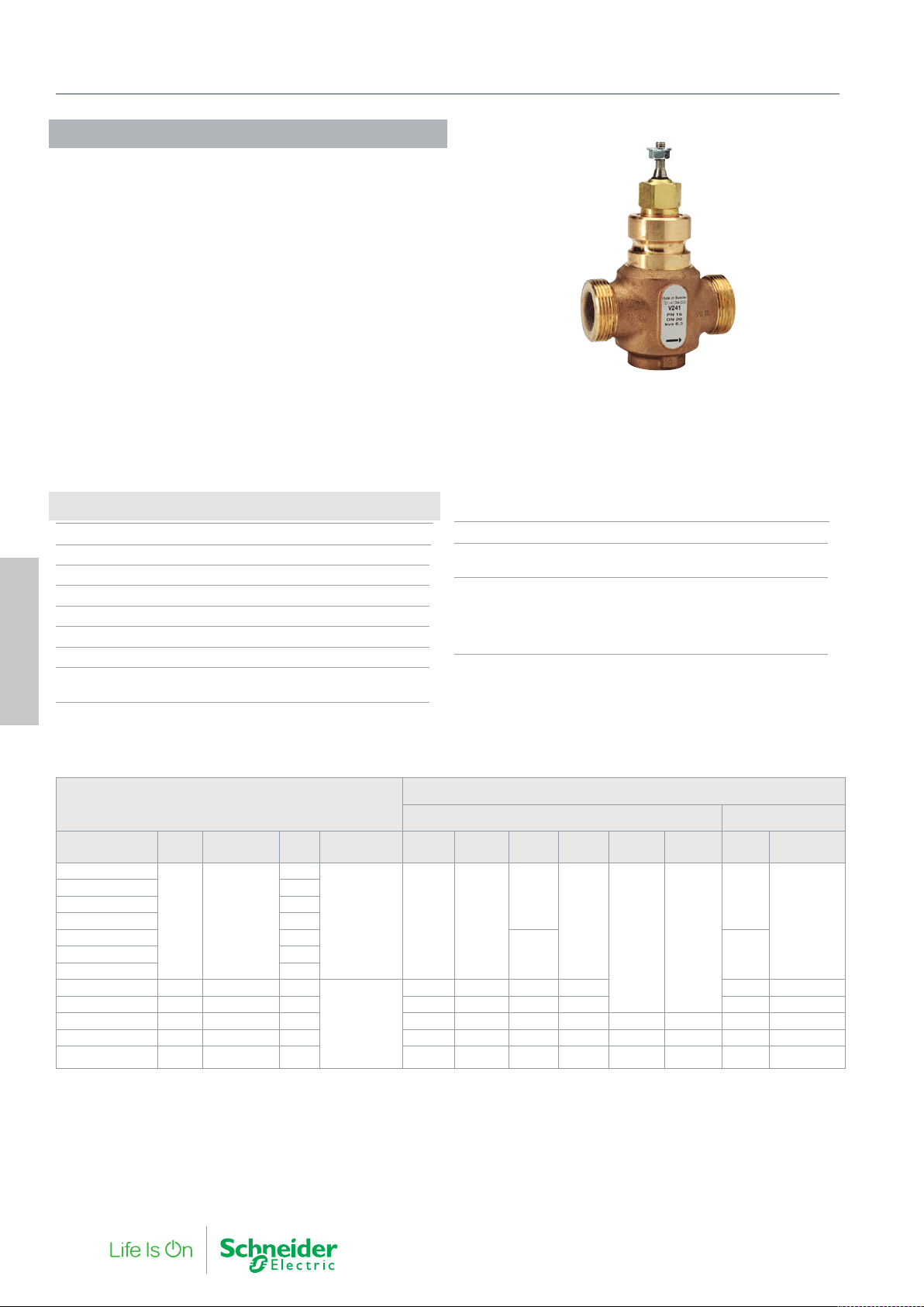
V241
The V241 is a high quality general purpose valve. Polished stainless
seats provide high differential pressure capability and low leakage.
Suitable for a wide range of applications such as heating, cooling,
air handling, domestic hot water, and district heating applications.
The valve can handle hot and cold water with phosphate, hydrazine
and antifreeze additives.
If the valve is used for media at temperatures below 0 °C (32°F), it
should be equipped with a heater to prevent ice formation on the
valve stem.
Specifications
Design 2-way plug valve, stem up closed
Pressure class PN 16
Flow characteristic Equal percentage modified
Stroke 20 mm
Rangeability (Kvs/Kv
Leakage up to 0.02% of Kv
∆Pm 600 kPa, water
Max. temperature of medium 150 °C
4. Globe Valves
Min. temperature of medium -20 °C
) (refer to table)
min.
Max. glycol/concentration 50%
Connection External pipe thread
according to ISO 228/1
Main Construction Materials
Body Bronze Rg5
Plug and seat Stainless steel SS 2346
Stem Stainless steel SS 2346
Stem packing EPDM
V241
Part Number DN Connection Kvs Rangeability M310 MG350 M400 M800 M1500
721 4106 000
721 4110 000 0.40
721 4114 000 0.63
721 4118 000 1.0
721 4122 000 1.6
721 4130 000 4.0
721 4134 000 20 G1¼B 6.3
721 4138 000 25 G1½B 10 400 400 500 1150 850 1160
721 4142 000 32 G2B 16 300 300 350 850 1350 1350 650 855
721 4146 000 40 G2¼B 25 150 150 250 600 950 950 450 605
721 4150 000 50 G2¾B 38 50 50 150 400 650 650 300 415
Replacement packing box: 1 001 0800 0
15 G1B
0.25
>50 800 800
>100
Max Close-off Pressure (kPa)
Non-spring Return Actuators Spring Return
MV15B
(1500N)
1000
1600
1600 1600
800 1400721 4126 000 2.5
650 650 650 1500 1100 1510
M700 MG900 SR
1600
1600
32 F-27878-6
Page 33
1
2
3
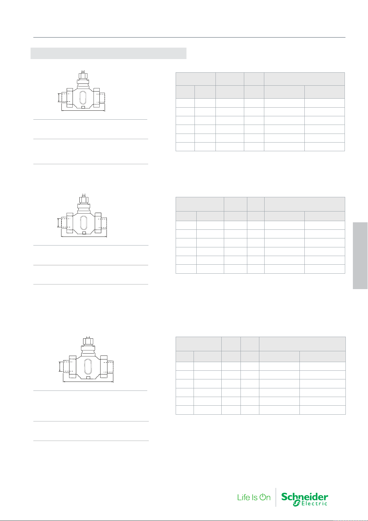
Connections V241
Internal Thread Connection
4. Globe Valves
ø d
1
AA
Main Construction Materials
Union nut malleable iron casting, galv.
Union end malleable iron casting, galv.
Packing, standard Fibre Gasket (Klingersil
C4400)
or Packing, spec PTFE Gasket (Kingersil Top
Chem 1.5 mm)
Soldering Type Connection
ø d
2
AA
Main Construction Materials
Union nut malleable iron casting, galv.
Union end Bronze, SS 5204
Packing, standard Fibre Gasket (Klingersil C4400)
or Packing, spec PTFE Gasket (Kingersil Top
Chem 1.5 mm)
Valve Ød
DN
End
Conn.
Int. thread
(ISO 7/1)
1
AA
mm Packing, std Packing, spec.*
Part Number for connection,
1
one pkg/port
15 G1B Rp ½ 146 911 2100 015 911 2103 015
20 G1¼B Rp ¾ 146 911 2100 020 911 2103 020
25 G1½B Rp 1 159 911 2100 025 911 2103 025
32 G2B
Rp 1¼
169 911 2100 032 911 2103 032
40 G2¼B Rp 1½ 197 911 2100 040 911 2103 040
50 G2¾B Rp 2 222 911 2100 050 911 2103 050
* The accessory intended for the primar y circuit of district heating connections.
Valve Ød
2
Part Number for connection,
AA
2
one pkg/port
DN End Conn. mm mm Packing, std Packing, spec.*
15 G1B 15 136 911 2101 015 911 2104 015
20 G1¼B 22 146 911 2101 020 911 2104 020
25 G1½B 28 155 911 2101 025 911 2104 025
32 G2B 35 163 911 2101 032 911 2104 032
40 G2¼B 42 200 911 2101 040 911 2104 040
50 G2¾B 54 232 911 2101 050 911 2104 050
* The accessory combination intended for the primary circuit of district heating connections.
4. Globe Valves
Welded Type Connection
Valve Ød
AA
3
DN End Conn. mm mm Packing, std Packing, spec.*
ø d
3
G1B 21.8 182
15
20 G1¼B 26.9 182 911 2102 020 911 2105 020 (1)
AA
Main Construction Materials
Union nut
Packing, standard Malleable iron casting, galv.
or Packing, Spec Brass
Union end malleable iron casting, galv.
Packing, standard Fibre Gasket (Klingersil C4400)
or Packing, spec PTFE Gasket (Kingersil Top
Chem 1.5 mm)
25 G1½B 33.7 187 911 2102 025 911 2105 025 (1)
32 G2B 42.4 197 911 2102 032 911 2105 032 (1)
40 G2¼B 48.3 232 911 2102 040 911 2105 040
50 G2¾B 60.3 262 911 2102 050 911 2105 050
(1) Material Union nut: brass SS 5252
* The accessory Combination intended for the primary circuit of district heating connections.
2 sets of connections required for 2-way valves
F-27878-6 33
Part Number for connection,
3
one pkg/port
911 2102 015 911 2105 015 (1)
Page 34
4. Globe Valves
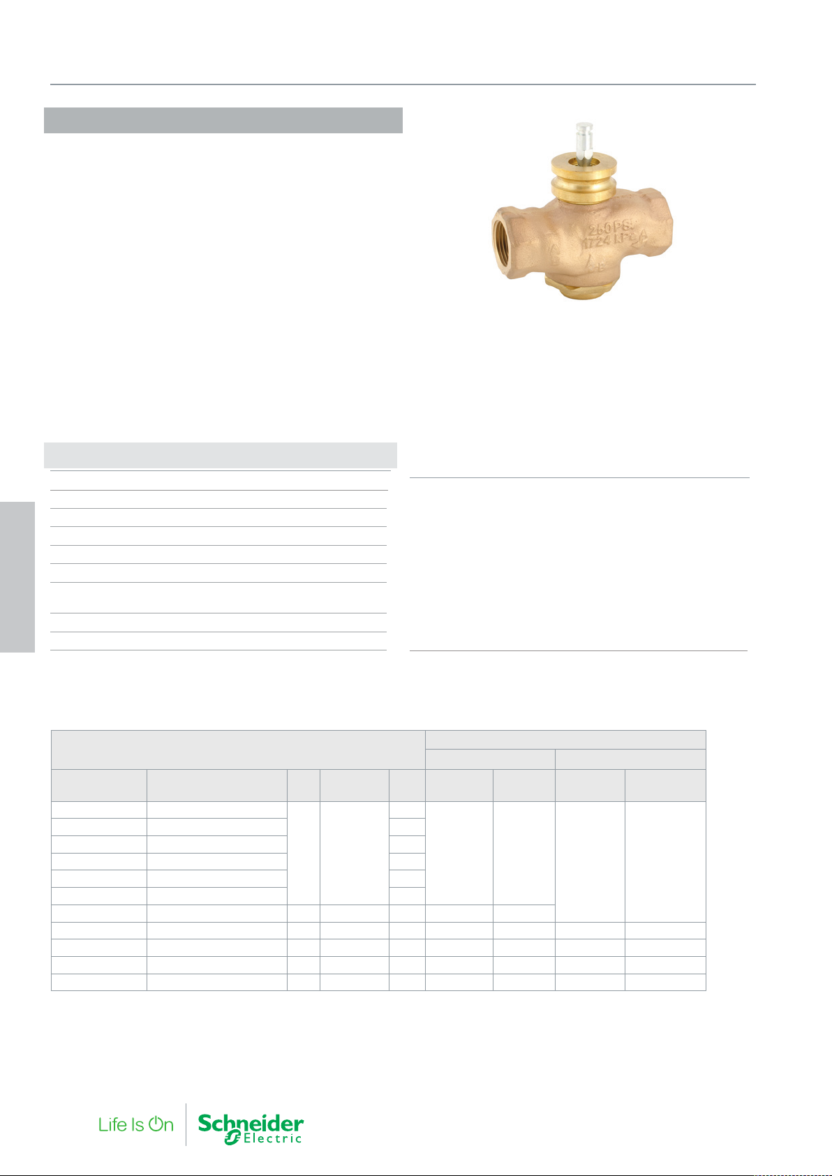
VG210R 15-50B
The Venta VG210R 15-50B is a range of compact precision bronze
globe valves, suitable for a wide range of fluid control applications,
including heating, cooling, air handling and domestic hot water
systems. The VG210R 15-50B series works reliably under a wide
variety of conditions, including fluids with high glycol concentrations
and very high temperature bands. The valve utilizes precision plugs
for improved rangeability and fine fluid control on small opening degrees. Soft seating also guards against seepage of precious energy
when not required.
Specifications
Design 2-way plug valve, stem up closed
Pressure class PN 16
Flow characteristic Equal percentage modified
Stroke 11 mm
Rangeability (Kvs/Kv
∆Pm 400 kPa, water
Max. temperature of medium 138 °C
Min. temperature of medium -7 °C
4. Globe Valves
Max. glycol concentration 60%
Connections Internal pipe thread Rp
) >100
min.
Main Construction Materials
Body Bronze; ASTM B584; CDA 83450
Oshalloy®
Bonnet / Packing Brass; UNS C36000 and
Cartridge chevrons PTFE/EPDM
Stem AISI 316 SS
Plug Brass; UNS C36000
Plug Seal EPDM, DN25…50
Seat Seal PTFE, DN15…20
Integral Seat Bronze; ASTM B584; CDA 83450
Oshalloy®
Slotted Stem Adaptor RoHS compliant Zinc-plated steel
VG210R 15-50B
Part Number
VG210R-15B02 VG210R 15B 0.4E SU 00
VG210R-15B03 VG210R 15B .63E SU 00 0.63
VG210R-15B04 VG210R 15B 1E SU 00 1.0
VG210R-15B05 VG210R 15B 1.6E SU 00 1.6
VG210R-15B07 VG210R 15B 2.5E SU 00 2.5
VG210R-15B08 VG210R 15B 4.0E SU 00 4.0
VG210R-20B VG210R 20B 6.3E SU 00 20 Rp 3/4 6.3 800 930
VG210R-25B VG210R 25B 10E SU 00 25 Rp 1 10 380 460 1100 1200
VG210R-32B VG210R 32B 17E SU 00 32 Rp 1¼ 17 250 290 600 700
VG210R-40B VG210R 40B 24E SU 00 40 Rp 1½ 24 100 170 350 450
VG210R-50B VG210R 50B 35E SU 00 50 Rp 2 35 55 69 90 240
a - Valves designed for direct connection onto compact Forta actuators, type MG600C. For all other Forta actuators, stem extention, code AV-823 is required. M700 and MV15B will not
connect to this valve. Leakage class as a percentage of a valves Kvs, EN60534-4. Replacement Bonnet, Packing Gland: YBA-689-C. Rangeability: 100:1
Type
Designation
DN Connection Kvs
15 Rp 1/2
Max Close-off Pressure (kPa a )
MG350C MG600C (-SR) Actuator
Class IV-S1
≤0.005%
0.4
1000 1500
Class IV1
≤0.01%
Class IV-S1
<0.005%
1600 1600
Class IV
>0.01%
34 F-27878-6
Page 35
V211T
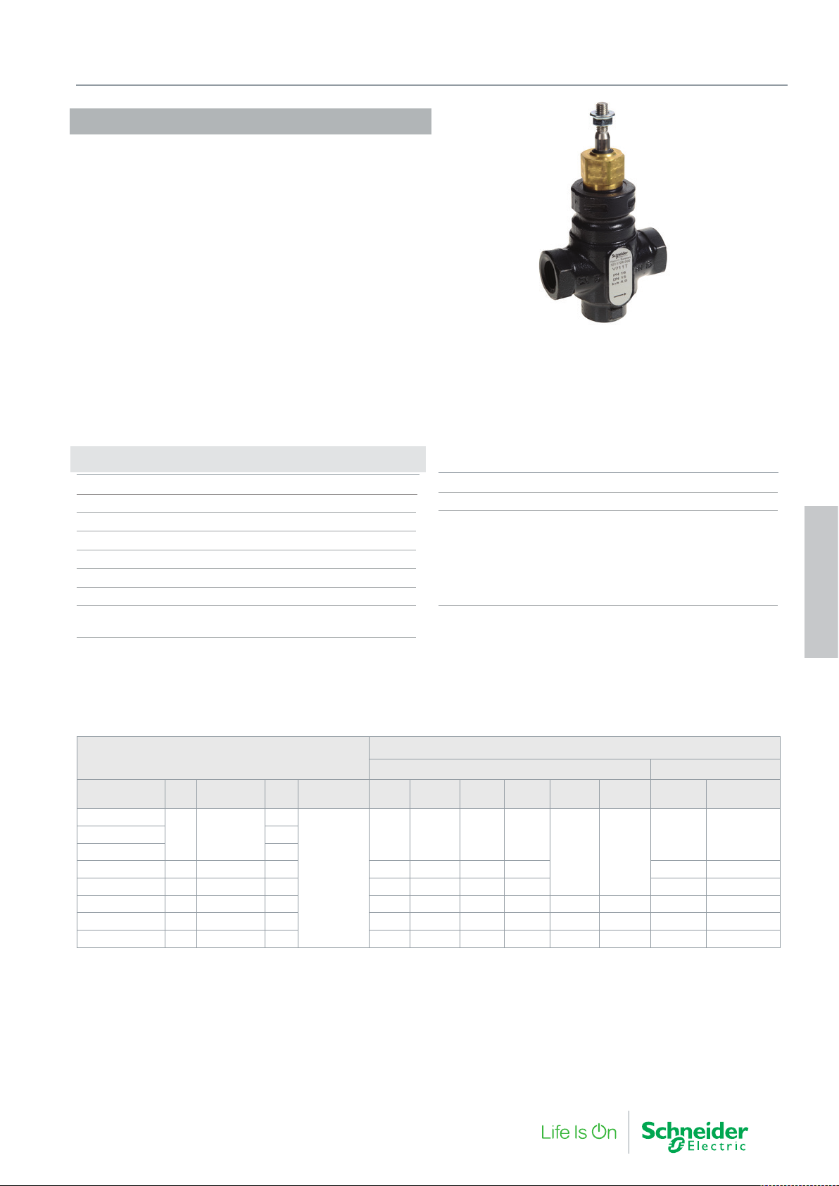
The V211T is an internally threaded valve with a soft seat for tight
shut off.
Suitable for a wide range of applications such as heating, cooling
and air handling systems with hot or chilled water.
If the valve is used for media at temperatures below 0 °C, it should
be equipped with a heater to prevent ice formation on the valve
stem.
Specifications
Design 2-way plug valve, stem up closed
Pressure class PN 16
Flow characteristic Equal percentage modified
Stroke 20 mm
Rangeability (Kvs/Kv
Leakage Tight sealing
∆Pm 400 kPa, water
Max. temperature of medium 120 °C
Min. temperature of medium -20 °C
) >50
min.
4. Globe Valves
Max. glycol concentration 50%
Connections Inter nal pipe thread Rp
Main Construction Materials
Body Nodular iron EN-JS 1030
Stem Stainless steel SS 2346
Plug Brass CW602N
Seat Sealing EPDM
Seat Nodular iron EN-JS 1030
Stem packing EPDM
4. Globe Valves
V211T
Part Number
721 1716 000
721 1724 000 4.0
721 1728 000 20 Rp 3/4 6.3 650 650 650 1500 1100 1510
721 1732 000 25 Rp 1 10 400 400 500 1150 850 1160
721 1736 000 32 Rp 1¼ 16 300 300 350 850 1350 1350 650 855
721 1740 000 40 Rp 1½ 25 150 150 250 600 950 950 450 605
721 1744 000 50 Rp 2 38 50 50 150 400 650 650 300 415
Replacement packing box: 1 001 0800 0
DN Connection Kvs Rangeability
15 Rp 1/2
1.6
>50
Max Close-off Pressure kPa
Non-spring Return Actuators Spring Return
M310 MG350 M400 M800 M1500
800 800 800 1600
1600 1600
MV15B
(1500N)
M700 MG900 SR
1400 1600721 1720 000 2.5
F-27878-6 35
Page 36
4. Globe Valves
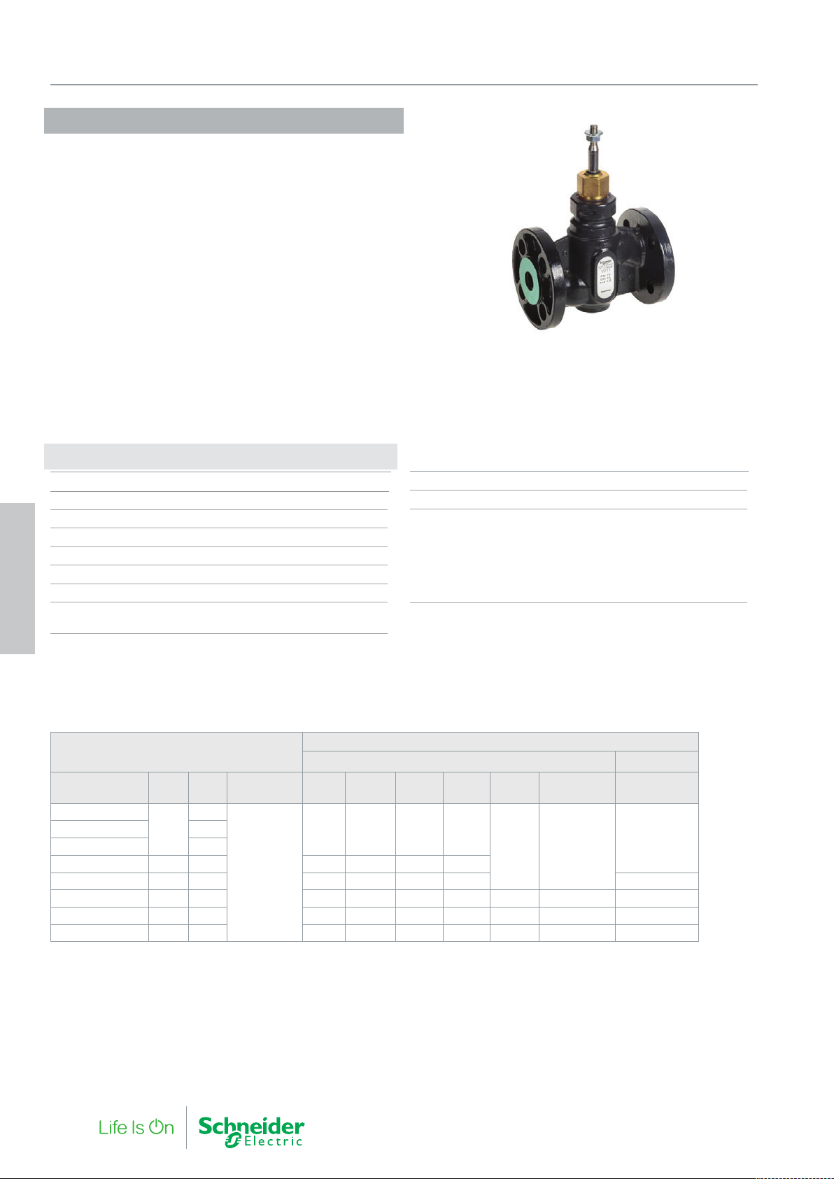
V211
The V211 is a flanged valve with a soft seat for tight shut off.
Suitable for a wide range of applications such as heating, cooling
and air handling systems with hot or chilled water.
If the valve is used for media at temperatures below 0 °C, it should
be equipped with a heater to prevent ice formation on the valve
stem.
Specifications
Design 2-way plug valve, stem up closed
Pressure class PN 16
Flow characteristic Equal percentage modified
Stroke 20 mm
Rangeability (Kvs/Kv
Leakage Tight sealing
∆Pm 400 kPa, water
Max. temperature of medium 120 °C
4. Globe Valves
Min. temperature of medium -20 °C
) >50
min.
Max. glycol/concentration 50%
Connections Flange according to ISO 7005-2
Main Construction Materials
Body Nodular iron EN-JS 1030
Stem Stainless steel SS 2346
Plug Brass CW602N
Plug Sealing EPDM
Seat Nodular iron EN-JS 1030
Stem packing EPDM
V211
Part Number DN Kvs Rangeability M310 MG350 M400 M800 M1500
721 1116 000
721 1120 000 2.5
721 1124 000 4.0
721 1128 000 20 6.3 650 650 650 1500
721 1132 000 25 10 400 400 500 1150 1160
721 1136 000 32 16 300 300 350 850 1350 1350 855
721 1140 000 40 25 150 150 250 600 950 950 605
721 1144 000 50 38 50 50 150 400 650 650 415
Replacement packing box: 1 001 0800 0
1.6
15
>50
Max Close-off Pressure (kPa)
Non-spring Return Actuators Spring Return
800 800 800 1600
MV15B
(1500N)
1600 1600
MG900 SR
1600
36 F-27878-6
Page 37
V212T
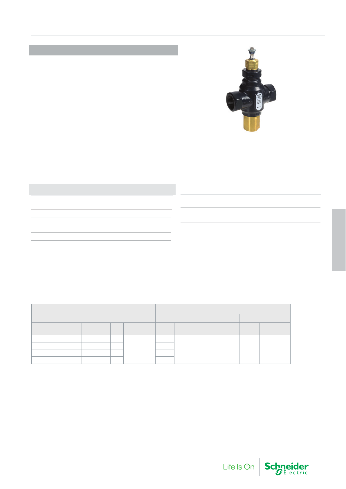
The V212T is an internally threaded balanced valve requiring only
minimal actuator force. Coupled with a soft seat and good rangeability the V212T provides very energy efficient control of hydronic
applications. If the valve is used for media at temperatures below 0
°C, it should be equipped with a heater to prevent ice formation on
the valve stem. Suitable for a wide range of applications such as
heating, cooling and air handling systems with hot or chilled water.
Specifications
Design 2-way pressure balanced plug
valve, stem up closed
Pressure class PN 16
Flow characteristic Equal percentage modified
Stroke 20 mm
Rangeability (Kvs/Kv
Leakage Tight sealing
∆Pm 400 kPa, water
) >50
min.
4. Globe Valves
Max. temperature of medium 120 °C
Min. temperature of medium -20 °C
Max. glycol/concentration 50%
Connections Internal pipe thread Rp
Main Construction Materials
Body Nodular iron EN-JS 1030
Stem Stainless steel SS 2346
Plug Brass CW602N
Seat Sealing EPDM
Seat Nodular iron EN-JS 1030
Stem packing EPDM
4. Globe Valves
V212T
Part Number DN Connection Kvs Rangeability M400 M800 M1500
721 1832 000 25 Rp 1 10
721 1836 000 32 Rp 1¼ 16 750
721 1840 000 40 Rp 1½ 25 700
721 1844 000 50 Rp 2 38 600
Replacement packing box: 1 001 0800 0
>50
Max Close-off Pressure (kPa)
Non-spring Return Actuators Spring Return
800
MV15B
(1500N)
1600 1600 1600 1600 1600
M700 MG900 SR
F-27878-6 37
Page 38
4. Globe Valves
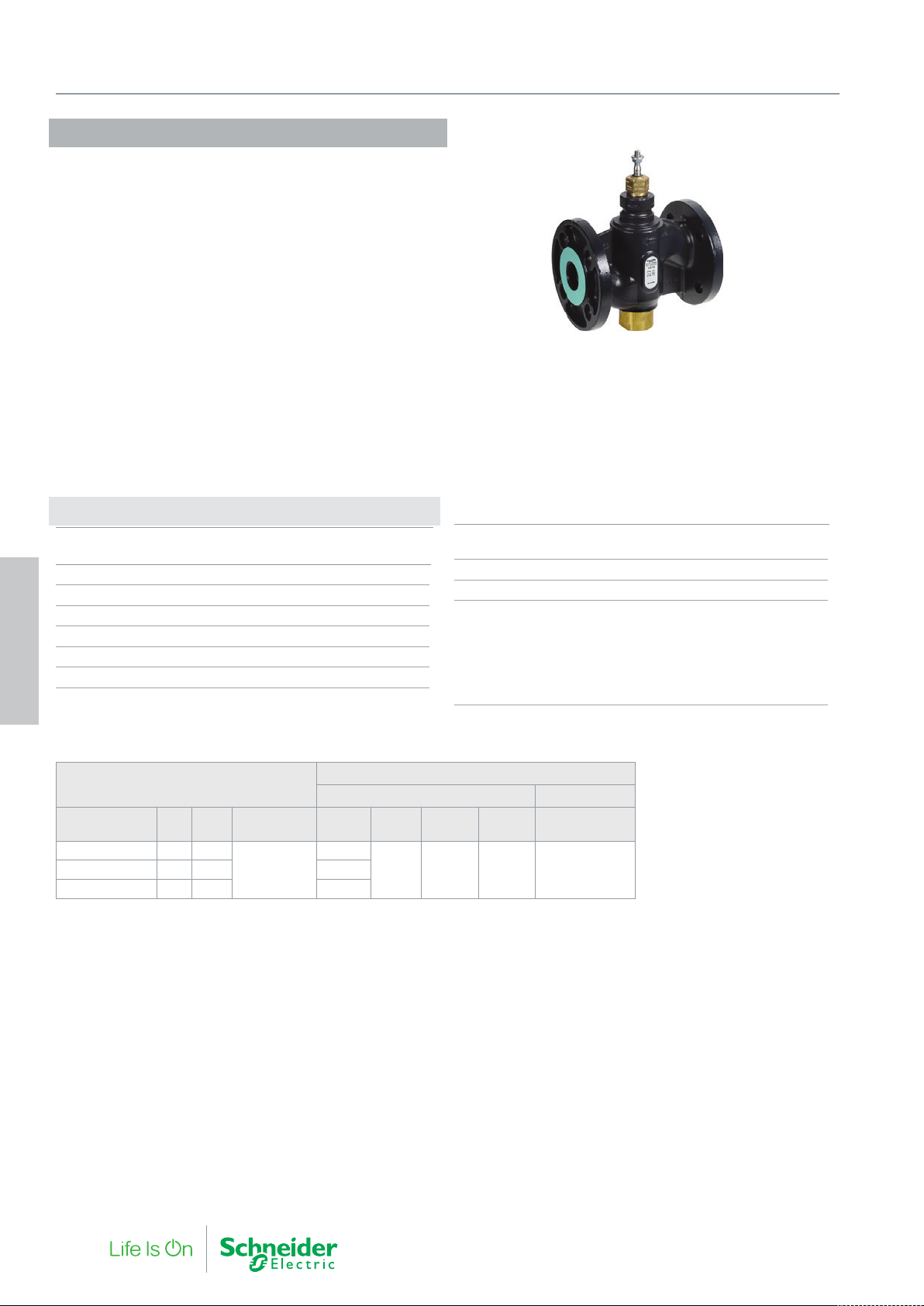
V212
The V212 is a flanged balanced valve requiring only minimal actuator force. Coupled with a soft seat and good rangeability the V212
provides very energy efficient control of hydronic applications.
Suitable for a wide range of applications such as heating, cooling
and air handling systems with hot or chilled water.
If the valve is used for media at temperatures below 0 °C, it should
be equipped with a heater to prevent ice formation on the valve
stem.
Specifications
Design 2-way pressure balanced plug valve,
stem up closed
Pressure class PN 16
Flow characteristic Equal percentage modified
Stroke 20 mm
Rangeability (Kvs/Kv
Leakage Tight sealing
∆Pm 400 kPa, water
4. Globe Valves
) >50
min.
Max. temperature of medium 120 °C
Min. temperature of medium -20 °C
Max.glycol/concentration 50%
Connections Flange according to ISO 7005-2
Main Construction Materials
Body Nodular iron EN-JS 1030
Stem Stainless steel SS 2346
Plug Brass CW602N
Sealing EPDM
Seat Nodular iron EN-JS 1030
Stem packing EPDM
V212
Part Number DN Kvs Rangeability M400 M800 M1500
721 1236 000 32 16
>50
721 1244 000 50 38 600
Replacement packing box: 1 001 0800 0
Max Close-off Pressure (kPa)
Non-spring Return Actuators Spring Return
750
1600 1600 1600 1600721 1240 000 40 25 700
MV15B
(1500N)
MG900 SR
38 F-27878-6
Page 39
VGS211F 15-100CS
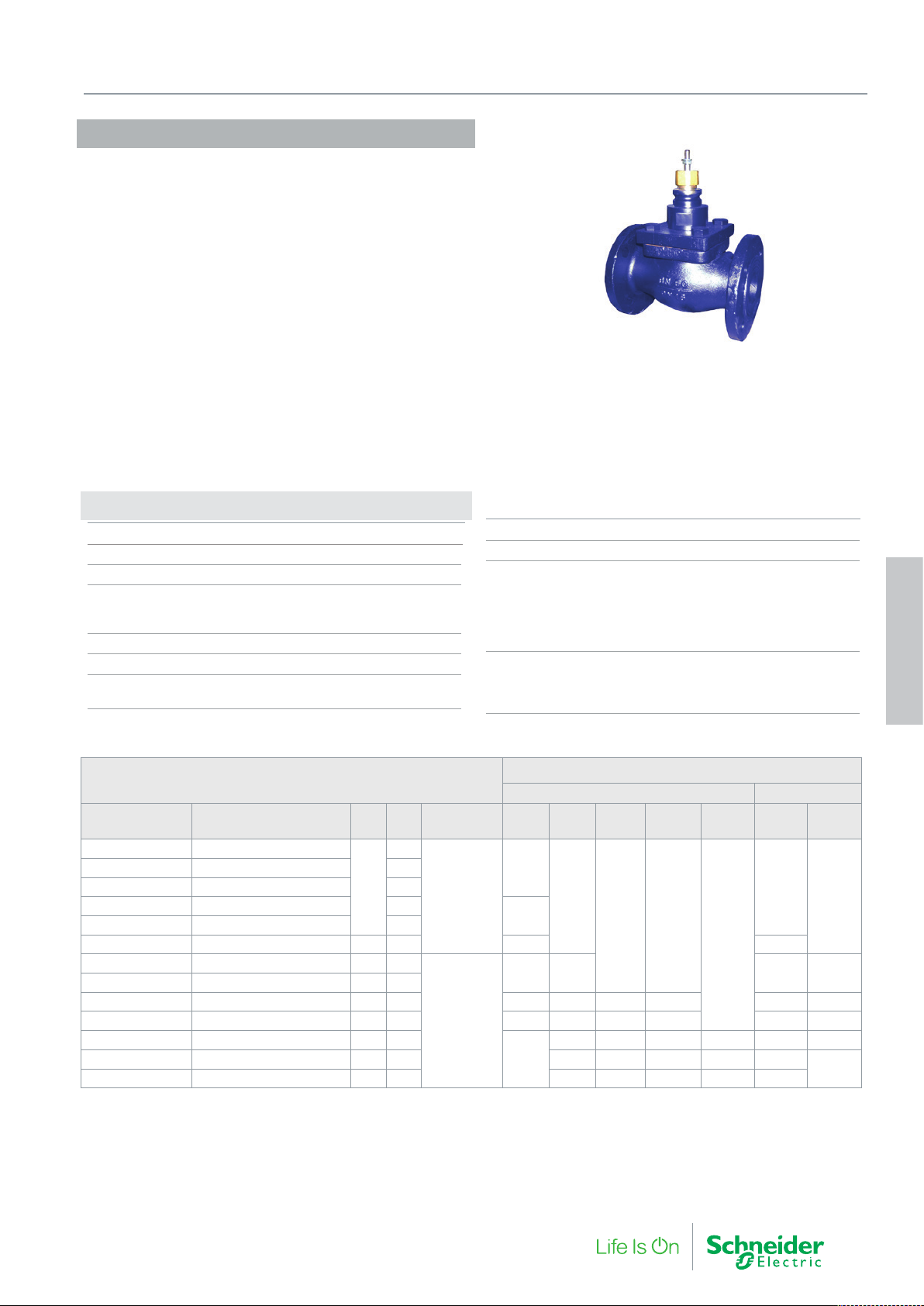
The VGS211F...CS is a flanged high temperature valve for media
temperatures up to 200ºC.
Primarily designed for steam but also suitable for a wide range of
applications such as heating, cooling and air
handling systems with hot or chilled water and steam.
If the valve is used for media at temperatures below 0 °C, it should
be equipped with a stem heater to prevent ice formation on the valve
stem.
Specifications
Design 2-way plug valve, stem up open
Pressure class PN 16
Flow characteristic Equal Percentage
Rangeability (Kvs/Kv
DN15…20 >50
DN25…100 >35
Leakage 0.02% of Kvs
∆Pm 600 kPa
Max. temperature of medium 200 °C
Min. temperature of medium -10 °C
min.
)
4. Globe Valves
Max. glycol/concentration 50%
Connections Flange according to ISO 7005-2
Main Construction Materials
Body Cast iron, EN-GJL 250
Stem Stainless steel (AISI 303)
Plug Stainless steel (AISI 303)
Seat Stainless steel (AISI 303)
Stem Packing Spring Loaded PTFE V-Ring
Stroke
DN15…DN25 16.5 mm
DN32…DN65 25 mm
DN80…DN100 45 mm
4. Globe Valves
VGS211F...CS
Part Number Type Designation DN Kvs Rangeability M400 M800 M1500
VGS211F-15CS03 VGS211F-15CS 0.63M SD00
VGS211F-15CS04 VGS211F-15CS 1M SD00 1.0
VGS211F-15CS05 VGS211F-15CS 1.6M SD00 1.6
VGS211F-15CS07 VGS211F-15CS 2.5M SD00 2.5
VGS211F-15CS08 VGS211F-15CS 4M SD00 4.0
VGS211F-20CS VGS211F-20CS 6.3 M SD00 20 6.3 750 1500
VGS211F-25CS VGS211F-25CS 10M SD00 25 10
VGS211F-32CS VGS211F-32CS 16M SD00 32 16
VGS211F-40CS VGS211F-40CS 24M SD00 40 24 250 800 1350 1350 550 800
VGS211F-50CS VGS211F-50CS 32M SD00 50 32 150 500 900 900 350 500
VGS211F-65CS VGS211F-65CS 63M SD00 65 63
VGS211F-80CS VGS211F-80CS 110M SD00 80 110 150 250 250 550 100
VGS211F-100CS VGS211F-100CS 140M SD00 100 140 90 150 150 350 60
Replacement packing box: 1 001 0811 0.
0.6
15
>50
>35
Max Close-off Pressure (kPa)
Non-spring Return Actuators Spring Return
MV 15B
(1500N)
1600
1600
1300
450 1300 900 1300
210 350 350 720 150 210
-
1600 1600
M3000 M700
1600
-
MG 900
SR
1600
-
F-27878-6 39
Page 40
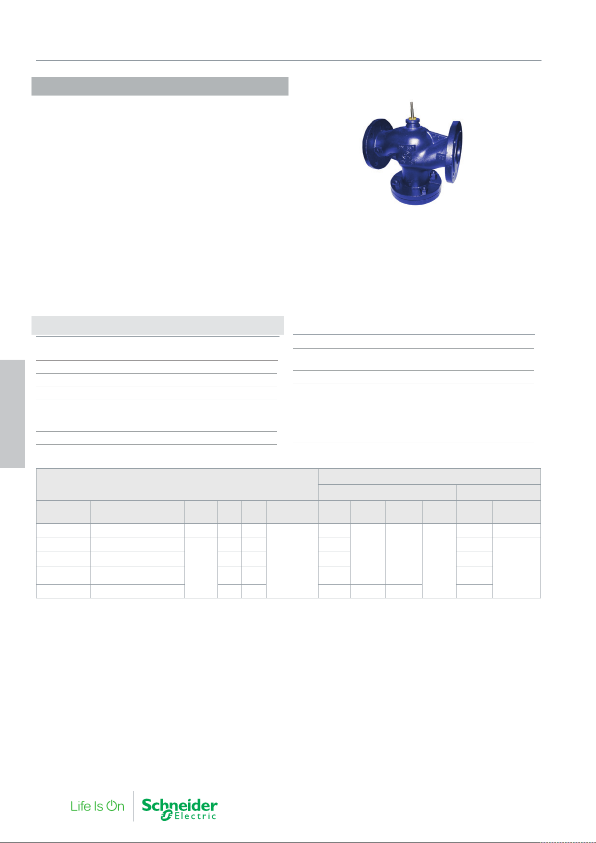
4. Globe Valves
VG221F 65-150C
The VG221F...C is a large flanged balanced valve suitable for large
hydronic flows in heating and air conditioning circuits. The balanced
plug enables a low actuating force to control the valve.
Suitable for a wide range of applications using hot water or deaerated cooling water
With cooling media at temperatures below 0 °C, a heater must be
fitted to protect against stem seizure due to freezing.
Specifications
Design 2-way pressure balanced plug valve,
stem up closed
Pressure class PN 16
Flow characteristics Equal Percentage
Rangeability (Kvs/Kv
Stroke
DN65 25 mm
DN80…DN150 45 mm
Leakage <0.03% of Kvs
4. Globe Valves
) >50
min.
∆Pm 200 kPa, water
Max. temperature of medium 150 °C
Min. temperature of medium -10 °C
Connection Flange according ISO 7005-2
Main Construction Materials
Body Grey cast iron (EN-GJL 250)
Stem stainless steel (AISI 303)
Plug Brass (CW614N)
Seat, Integrated Grey cast iron (EN-GJL 250)
Stem Packing EPDM
VG221F...C
Part Number Type Designation Stroke DN Kvs Rangeability M800 M1500
VG221F-65C VG221F-65C 63M SU00 25 65 63
VG221F-80C VG221F-80C 100M SU00
VG221F-100C VG221F-100C 130M SU00 100 130 1000 700
VG221F-125C VG221F-125C 200M SU00 125 200 750 470
VG221F-150C VG221F-150C 300M SU00 150 300 550 1450 1450 300
Replacement packing box: 1 001 0810 0
45
80 100 1450 1000
>50
Max Close-off Pressure (kPa)
Non-spring Return Actuators Spring Return
1600
MV15B
(1500N)
1600 1600
M3000 M700 MG900 SR
1600
1300 1600
-
40 F-27878-6
Page 41
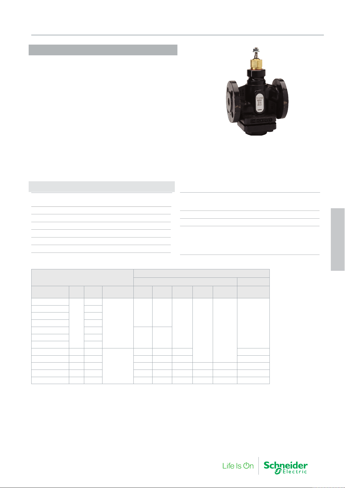
V231
The V231 is a flanged PN25 valve with a very high rangeability.
The valve is suitable for primary district heating circuits as well as
hot and chilled water applications where high pressure or where a
very fine resolution of flow control is required.
If the valve is used for media at temperatures below 0 °C, it should
be equipped with a heater to prevent ice formation on the valve
stem.
Specifications
Design 2-way plug valve,
stem up closed
Pressure class PN 25
Flow characteristic Equal percentage modified
Stroke 20 mm
Rangeability (Kvs/Kv
Leakage Up to 0.02% of Kvs
∆Pm Max. 800 kPa, water
) (refer to table)
min.
4. Globe Valves
Max. temperature, water 150 °C
Max. temperature, saturated steam 120 °C
Min. temperature of medium -20 °C
Max. Glycol concentration 50%
Flanges drilling According to SS 335 and ISO 2084
Main Construction Materials
Body Nodular iron SS 0727 (GGG40.3)
Plug and seat Stainless steel SS 2346
Stem Stainless steel SS 2346
Stem Packing EPDM
4. Globe Valves
V231
Part Number DN Kvs Rangeability M310 M400 M800 M1500
721 3106 000
721 3110 000 0.40
721 3114 000 0.63
721 3118 000 1.0
721 3122 000 1.6
721 3130 000 4.0
721 3134 000 20 6.3
721 3138 000 25 10 400 500 1150 1150
721 3142 000 32 16 300 350 850 1350 1350 850
721 3146 000 40 25 150 250 600 950 950 600
721 3150 000 50 38 50 150 400 650 650 400
Replacement packing box: 1 001 0800 0
0.25
15
>50
>200
Max Close-off Pressure (kPa)
Non-spring Return Actuators Spring Return
MV15B
(1500N)
1000 1000
1600
1600 1600
800 800721 3126 000 2.5
650 650 1500 1500
MG900 SR
1600
F-27878-6 41
Page 42
4. Globe Valves
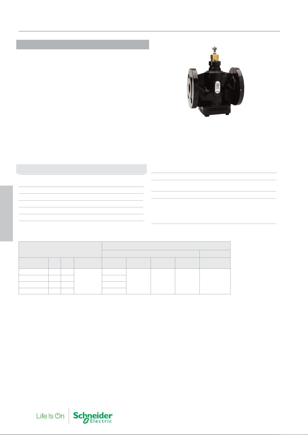
V232
The V232 is a pressure balanced flanged PN25 valve with high
rangeability and a high differential pressure capability. The balanced
plug enables a low actuating force to control the valve.
The valve is suitable for primary district heating circuits as well as
hot and chilled water applications where high pressure or a very fine
resolution of controllable flow is required.
If the valve is used for media at temperatures below 0 °C, it should
be equipped with a heater to prevent ice formation on the valve
stem.
Specifications
Design 2-way, pressure balanced plug valve,
stem up closed
Pressure class PN 25
Flow characteristic Equal percentage modified
Stroke 20 mm
Rangeability (Kvs/Kv
Leakage Up to 0.02% of Kvs
4. Globe Valves
) (refer to table)
min.
∆Pm Max. 800 kPa, water
Max. temperature of medium 150 °C
Min. temperature of medium -20 °C
Flange drilling According to SS 335 and ISO 2084
Main Construction Materials
Body Nodular iron SS 0727 (GGG40.3)
Plug and seat Stainless steel SS 2346
Stem Stainless steel SS 2346
Stem packing EPDM
V232
Part Number DN Kvs Rangeability M400 M800 M1500
721 3238 000 25 10
721 3242 000 32 16 750
721 3246 000 40 25 700
721 3250 000 50 38 600
Replacement packing box: 1 001 0800 0
>200
Max Close-off Pressure (kPa)
Non-spring Return Actuators Spring Return
800
1600 1600 1600 1600
MV15B
(1500N)
MG900 SR
42 F-27878-6
Page 43
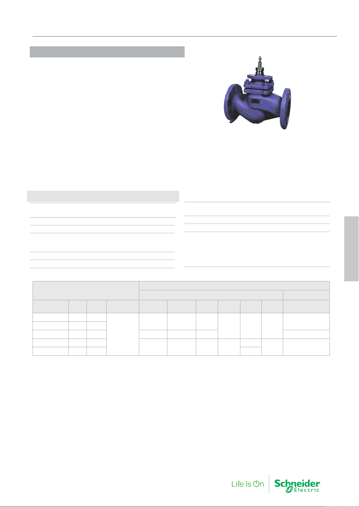
V292
The V292 is a large pressure balanced flanged valve to PN25. The
balanced plug enables a low actuating force to control the valve.
The valve is suitable for primary district heating circuits as well as
high pressure hot and chilled water applications
Specifications
Design 2-way pressure balanced plug
valve stem down, closed
Pressure class PN 25
Flow characteristics Equal Percentage
Stroke
DN65…DN100 30 mm
DN125…DN150 50 mm
Rangeability (Kvs/Kv
Leakage <0.05% of Kvs
) > 50
min.
4. Globe Valves
Max. temperature of medium 150 °C
Min. temperature of medium -10 °C
Max. Glycol concentration 50%
Connection Flange according ISO 7005-2
Main Construction Materials
Body Nodular iron GGG40.3
Stem Stainless steel SS 1.4021
Plug Stainless steel SS 1.4021
Seat Stainless steel SS 1.4021
Packing box Spring-loaded PTFE-V-ring
4. Globe Valves
V292
Part Number DN Kvs Rangeability M800 M1500 MV15B M3000
721 9254 000 65 63
721 9258 000 80 85
721 9262 000 100 130 1100 1600 1600 800
721 9266 000 125 250
721 9270 000 150 350 1400
Replacement packing box
DN65…DN100: 1 001 0820 0
DN125…DN150: 1 001 0821 0
Stem Heater
DN65…DN100: 880 0112 000
DN125…DN150: 880 0113 000
Replacement stem adaptor/hex bush:
DN125…DN150: 880 0134 000
>50
Max Close-off Pressure (kPa)
Non-spring Return Actuators Spring Return
1500 2500 2500
- - - -
M22
(2200N)
2500 - -
1800
M50
(5000N)
2500
2500
M700
1200
-
F-27878-6 43
Page 44
4. Globe Valves
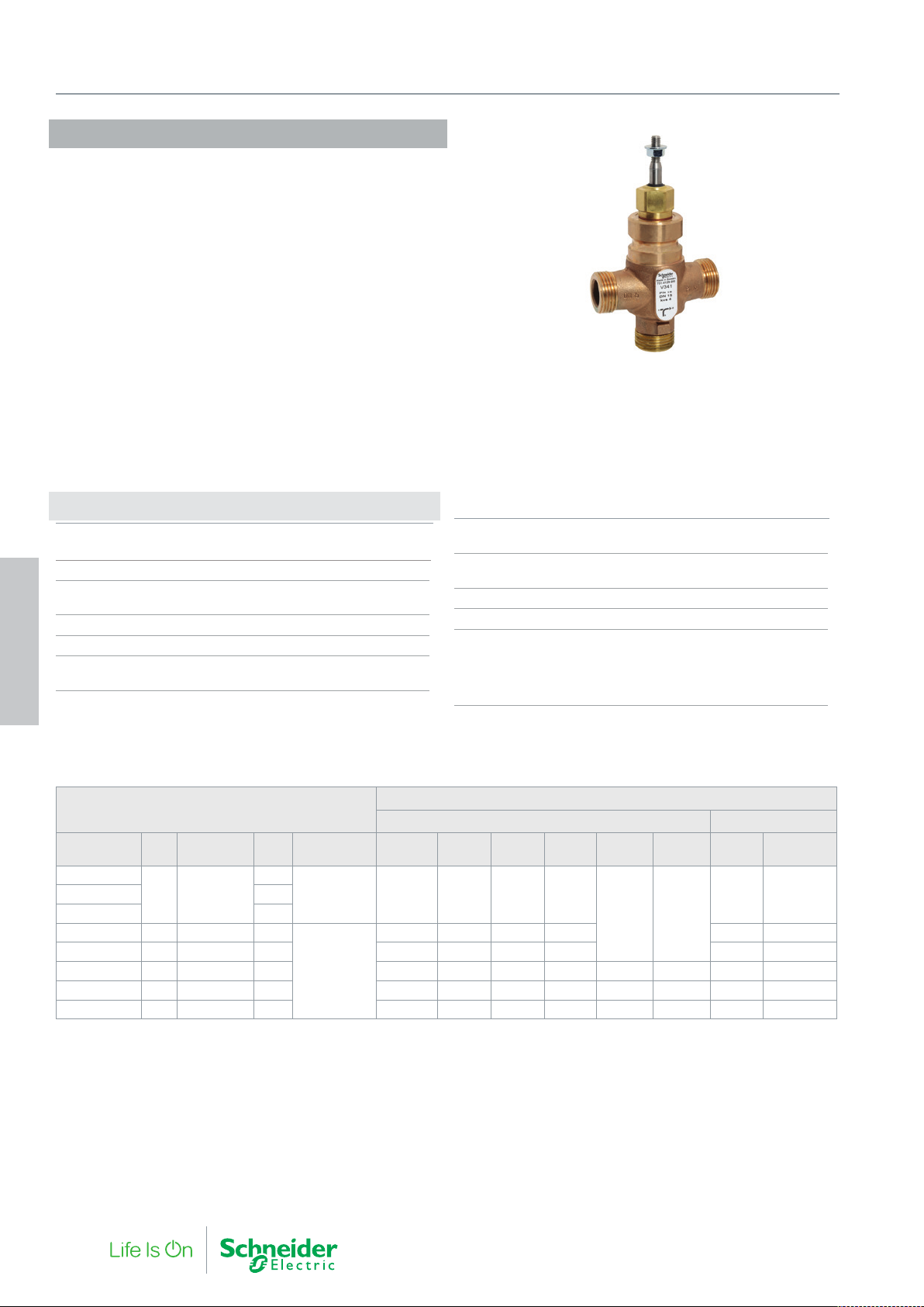
V341
The V341 is a high quality general purpose valve. Polished stainless
seats provide high differential pressure capability and low leakage.
The valve is suitable for a wide range of applications such as heating, cooling, air handling and domestic hot water systems. The
valve can handle hot and cold water with phosphate, hydrazine and
antifreeze additives.
If the valve is used for media at temperatures below 0 °C, it should
be equipped with a heater to prevent ice formation on the valve
stem.
Specifications
Design 3-way plug valve
Stem up closed, A port (B-AB open)
Pressure class PN 16
Flow characteristics A-AB Equal percentage modified
Flow characteristics B-AB Complementary
Stroke 20 mm
Rangeability (Kvs/Kv
Leakage A-AB up to 0.02% of Kvs
Leakage B-AB up to 0.05% of Kvs
4. Globe Valves
) (refer to table)
min.
∆Pm (mixing) 600 kPa, water
∆Pm (diverting) 60 kPa, water
Max. temperature of medium 150 °C
Min. temperature of medium -20 °C
Connection External pipe thread according to ISO 228/1
Glycol Concentration 50%
Main Construction Materials
Body Bronze Rg5
Plug and seat Stainless steel SS 2346
Stem Stainless steel SS 2346
Stem packing EPDM
V341
Part Number DN Connection Kv s Rangeability M310 MG350 M400 M800 M1500
731 4121 000
15 G1B
731 4129 000 4.0
731 4133 000 20 G1¼B 6.3
731 4137 000 25 G1½B 10 400 400 500 1150 850 1160
731 4141 000 32 G2B 16 300 300 350 850 1350 1350 650 855
731 4145 000 40 G2¼B 25 150 150 250 600 950 950 450 605
731 4149 000 50 G2¾B 38 50 50 150 400 650 650 300 415
Replacement packing box: 1 001 0800 0
1.6
>50 800 800 800 1600
>100
Max Close-off Pressure (kPa)
Non-spring Return Actuators Spring Return
MV15B
(1500N)
1600 1600
650 650 650 1500 1100 1510
M700 MG900 SR
1400 1600731 4125 000 2.5
44 F-27878-6
Page 45
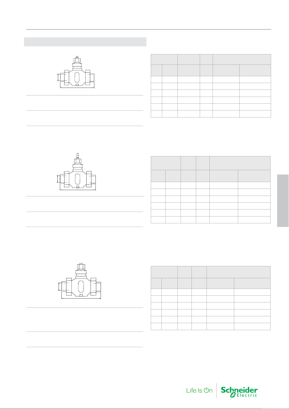
Connections V341
1
2
3
Internal Thread Connection
ø d
1
AA
Main Construction Materials
Union nut malleable iron casting, galv.
Union end malleable iron casting, galv.
Packing, standard Fibre Gasket (Klingersil C4400)
or Packing, spec PTFE Gasket (Kingersil Top
Chem 1.5 mm)
Soldering Type Connection
4. Globe Valves
Valve Ød
End
DN
Conn.
1
Int. thread
(ISO 7/1)
15 G1B Rp ½ 146 911 2100 015 911 2103 015
20 G1¼B Rp ¾ 146 911 2100 020 911 2103 020
25 G1½B Rp 1 159 911 2100 025 911 2103 025
32 G2B Rp 1¼ 169 911 2100 032 911 2103 032
40 G2¼B Rp 1½ 197 911 2100 040 911 2103 040
50 G2¾B Rp 2 222 911 2100 050 911 2103 050
* The accessory intended for the primar y circuit of district heating connections.
Part Number for connection,
AA
1
one pkg/port
mm Packing, std Packing, spec.*
ø d
2
AA
Main Construction Materials
Union nut malleable iron casting, galv.
Union end Bronze, SS 5204
Packing, standard Fibre Gasket (Klingersil C4400)\
or Packing, spec PTFE Gasket (Kingersil Top
Chem 1.5 mm)
Welded Type Connection
ø d
3
AA
Main Construction Materials
Union nut
Packing, standard Malleable iron casting, galv.
or Packing, Spec Brass
Union end malleable iron casting, galv.
Packing, standard Fibre Gasket (Klingersil C4400)
or Packing, spec PTFE Gasket (Kingersil Top
Chem 1.5 mm)
Valve Ød
DN
End
Conn.
mm mm Packing, std Packing, spec.*
2
Part Number for connection,
AA
2
one pkg/port
15 G1B 15 136 911 2101 015 911 2104 015
20 G1¼B 22 146 911 2101 020 911 2104 020
25 G1½B 28 155 911 2101 025 911 2104 025
32 G2B 35 163 911 2101 032 911 2104 032
40 G2¼B 42 200 911 2101 040 911 2104 040
50 G2¾B 54 232 911 2101 050 911 2104 050
* The accessory combination intended for the primary circuit of district heating
connections.
Valve Ød
End
DN
Conn.
AA
3
mm mm Packing, std Packing, spec.*
15 G1B 21.8 182 911 2102 015 911 2105 015
20 G1¼B 26.9 182 911 2102 020 911 2105 020
25 G1½B 33.7 187 911 2102 025 911 2105 025
32 G2B 42.4 197 911 2102 032 911 2105 032
Part Number for connection,
3
one pkg/port
1
1
1
1
40 G2¼B 48.3 232 911 2102 040 911 2105 040
50 G2¾B 60.3 262 911 2102 050 911 2105 050
1 - Material Union nut: brass SS 5252
* The accessory Combination intended for the primary circuit of district heating connections.
3 sets of connections required for 3-way valves
4. Globe Valves
F-27878-6 45
Page 46
4. Globe Valves
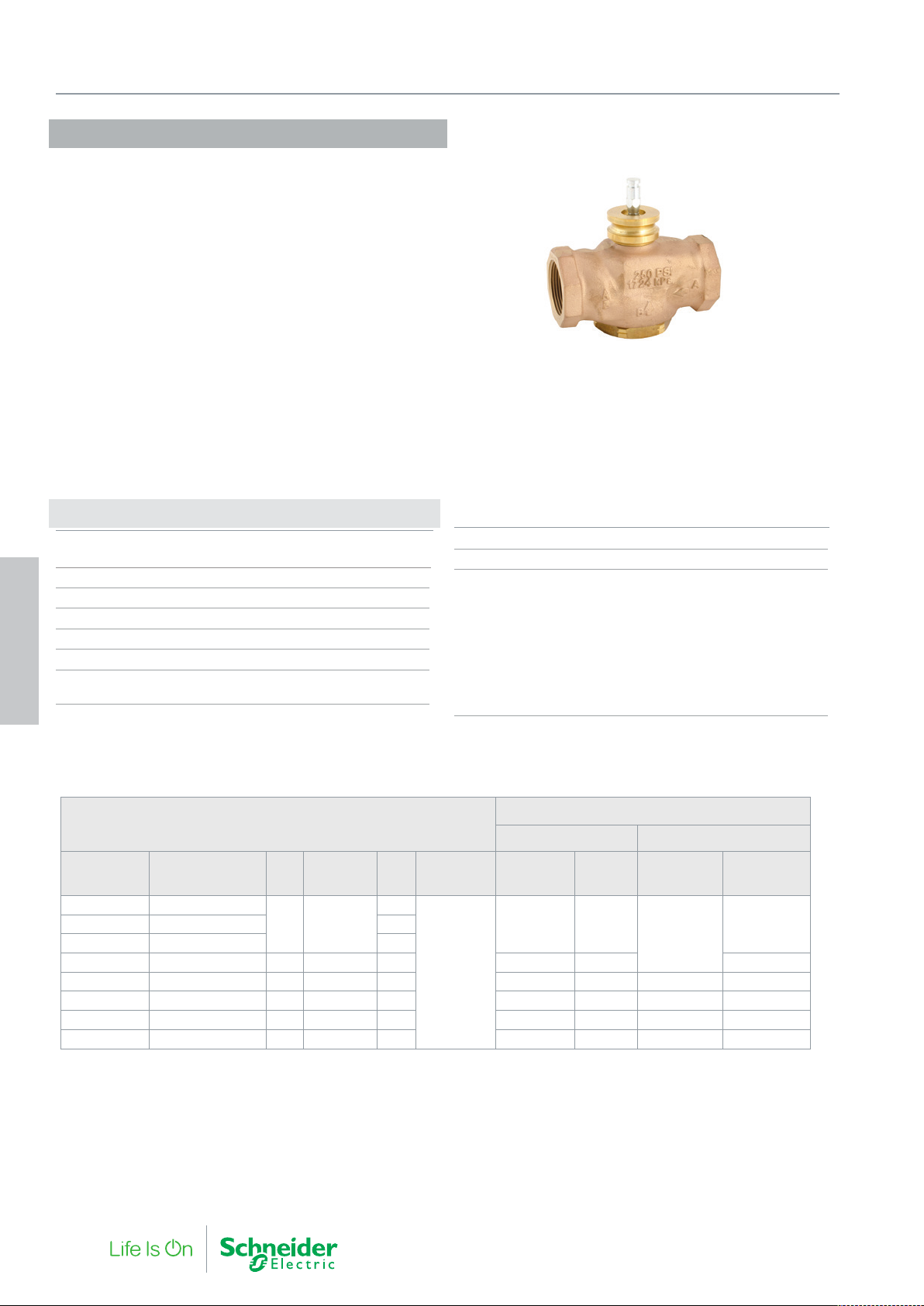
VG310R 15-50B
The Venta VG310R 15-50B is a range of compact precision bronze
globe valves, suitable for a wide range of fluid control applications,
including heating, cooling, air handling and domestic hot water systems. The VG310R 15-50B series works reliably under a wide variety
of conditions, including fluids with high glycol concentrations and
very high temperature bands.
The valve utilizes precision plugs for improved rangeability and fine
fluid control on small opening degrees. Soft seating provides an ultra
tight close off performance against energy seepage.
Specifications
Design 3-way plug valve,
stem up closed
Pressure class PN 16
Flow characteristic Equal percentage modified
Stroke 11 mm
Rangeability (Kvs/Kv
) >100
min.
∆Pm 400 kPa, water
Max. temperature of medium 138 °C
4. Globe Valves
Min. temperature of medium -7 °C
VG310R 15-50B
Part Number aType Designation DN Connection Kvs Rangeability
VG310R-15B05 VG310R-15B 1.6T SU00
15 Rp 1/2
VG310R-15B08 VG310R-15B 4T SU00 4.0
VG310R-20B VG310R-20B 6.3T SU00 20 Rp 3/4 6.3 800 930 1600
VG310R-25B VG310R-25B 10E SU00 25 Rp 1 10 380 460 1100 1200
VG310R-32B VG310R-32B 17E SU00 32 Rp 1¼ 17 250 290 600 700
VG310R-40B VG310R-40B 24E SU00 40 Rp 1½ 24 100 170 350 450
VG310R-50B VG310R-50B 35E SU00 50 Rp 2 35 55 69 90 240
a. Valves designed for direct connection onto compact Forta actuators, type MG600C, MG600C-SR. For all other Forta actuators, stem extention, code AV-823 is
required. It is not possible to drive this valve with the M700 or MV15B actuator.
Replacement Bonnet, Packing Gland: YBA-689-C
1.6
Max. glycol concentration 60%
Connections Inter nal pipe thread Rp
Main Construction Materials
Body Bronze
Stem Stainless steel 316
Plug Brass CW602N
Sealing PTFE for 15 and
20 mm units. EPDM for others.
Seat Bronze
Standard packing box Brass with PTFE and EPDM Chevrons
Slotted Stem Adapter RoHS compliant
Zinc-plated Steel
Max Close-off Pressure (kPa)
with MG350C with MG600C (-SR) actuator
>100
Class IV-S1
≤0.005%
1000 1500
IV1
≤0.01%
Class IV-S1
≤0.005%
1600
Class IV
≤0.01%
1600VG310R-15B07 VG310R-15B 2.5T SU00 2.5
46 F-27878-6
Page 47
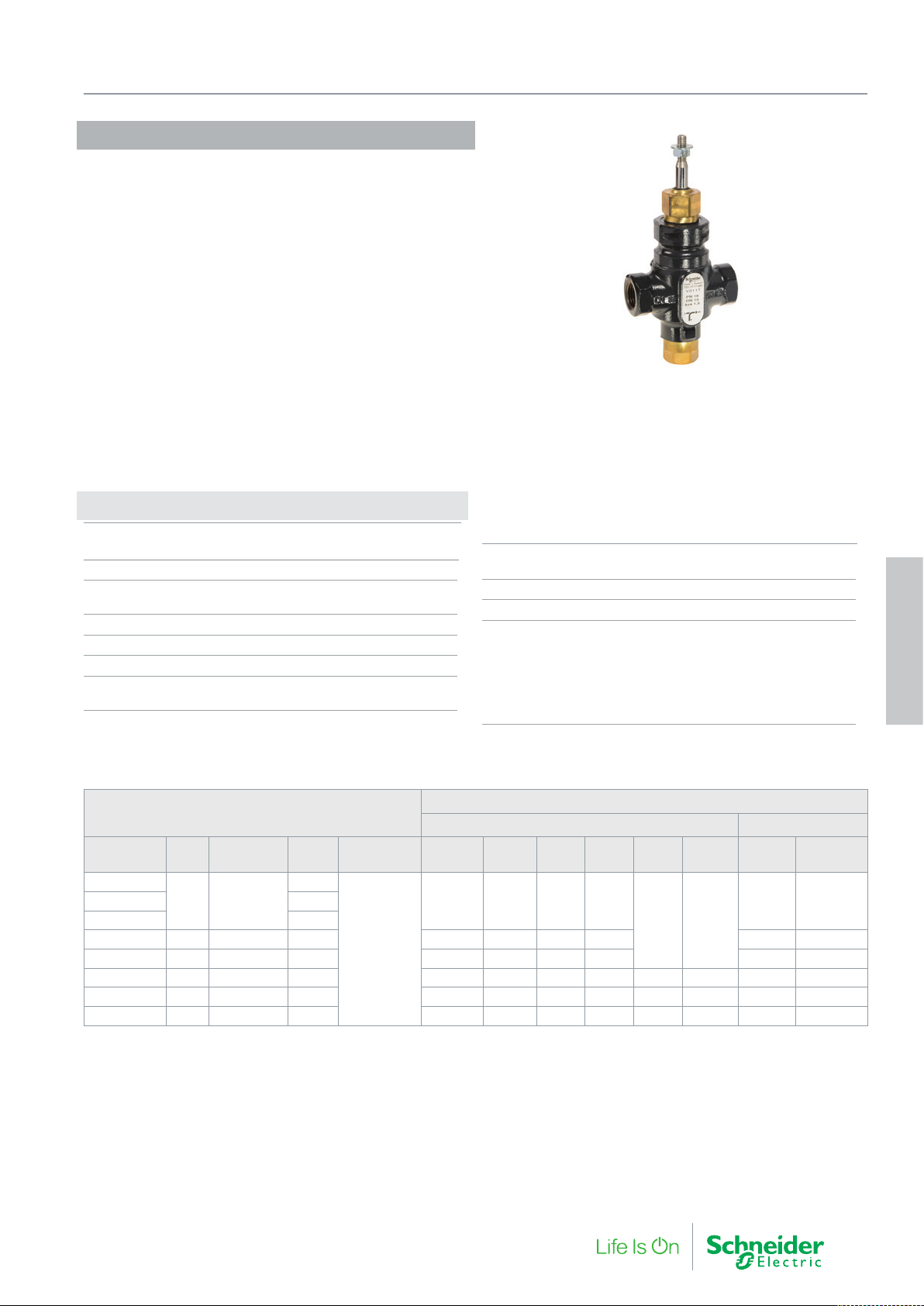
V311T
The V311T is an internally threaded valve with a soft seat for tight
shut off.
If the valve is used for media at temperatures below 0 °C, it should
be equipped with a heater to prevent ice formation on the valve
stem.
Specifications
Design 3-way plug valve
stem up closed, A port (B-AB open)
Pressure class PN 16
Flow characteristic A-AB Equal percentage modified
Flow characteristic B-AB Complementary
Stroke 20 mm
Rangeability (Kvs/Kv
Leakage A-AB and B-AB Tight sealing
∆Pm (mixing) 400 kPa, water
∆Pm (diverting) 60 kPa, water
) >50
min.
4. Globe Valves
Max. temperature of medium 120 °C
Min. temperature of medium -20 °C
Max. Glycol concentration 50%
Connection Internal pipe thread Rp
Main Construction Materials
Body Nodular iron EN-JS 1030
Stem Stainless steel SS 2346
Plug Brass CW602N
Sealing EPDM
Seat Nodular iron EN-JS 1030
Stem packing EPDM
4. Globe Valves
V311T
Part Number DN Connection Kvs Rangeability M310 MG350 M400 M800 M1500
731 1717 000
731 1721 000 2.5
731 1725 000 4.0
731 1729 000 20 Rp 3/4 6.3 650 650 650 1500 1100 1510
731 1733 000 25 Rp 1 10 400 400 500 1150 850 1160
731 1737 000 32 Rp 1¼ 16 300 300 350 850 1350 1350 650 605
731 1741 000 40 Rp 1½ 25 150 150 250 600 950 950 450 604
731 1745 000 50 Rp 2 38 50 50 150 400 650 650 300 415
Replacement packing box: 1 001 0800 0
15 Rp 1/2
1.6
>50
Max Close-off Pressure (kPa)
Non-spring Return Actuators Spring Return
800 800 800 1600
MV15B
(1500N)
1600 1600
M700 MG900SR
1400 1600
F-27878-6 47
Page 48
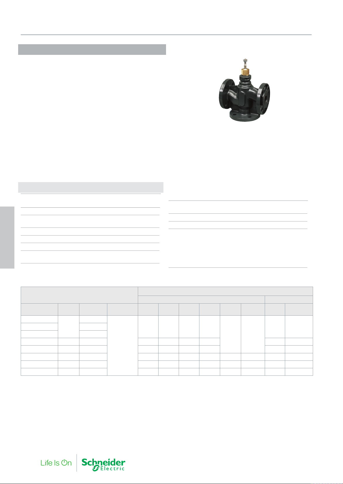
4. Globe Valves
V311
The V311 is a flanged valve with a soft seat for tight shut off.
The valve is suitable for a wide range of mixing applications with hot
or chilled water in heating cooling and air handling systems.
If the valve is used for media at temperatures below 0 °C, it should
be equipped with a stem heater to prevent ice formation on the valve
stem.
Specifications
Design 3-way plug valve
stem up closed (A port/B-AB open)
Pressure class PN 16
Flow characteristic A-AB Equal percentage modified
Flow characteristic B-AB Complementary
Stroke 20 mm
Rangeability (Kvs/Kv
Leakage A-AB and B-AB Tight sealing
∆Pm (mixing) 400 kPa, water
4. Globe Valves
∆Pm (diverting) 60 kPa, water
) >50
min.
Max. temperature of medium 120 °C
Min. temperature of medium -20 °C
Max. Glycol concentration 25%
Connection Flange according to ISO 7005-2
Main Construction Materials
Body Nodular iron EN-JS 1030
Stem Stainless steel SS 2346
Plug Brass CW602N
Sealing EPDM
Seat Nodular iron EN-JS 1030
Stem Packing EPDM
V311
Part Number DN Kvs Rangeability M310 MG350 M400 M800 M1500
731 1117 000
15
731 1125 000 4.0
731 1129 000 20 6.3 650 650 650 1500 1100 1510
731 1133 000 25 10 400 400 500 1150 850 1160
731 1137 000 32 16 300 300 350 850 1350 1350 650 855
731 1141 000 40 25 150 150 250 600 950 950 450 605
731 1145 000 50 38 50 50 150 400 650 650 300 415
Replacement packing box: 1 001 0800 0
1.6
>50
Max Close-off Pressure (kPa)
Non-spring Return Actuators Spring Return
800 800 800 1600
MV15B
(1500N)
1600 1600
M700 MG900 SR
1400 1600731 1121 000 2.5
48 F-27878-6
Page 49
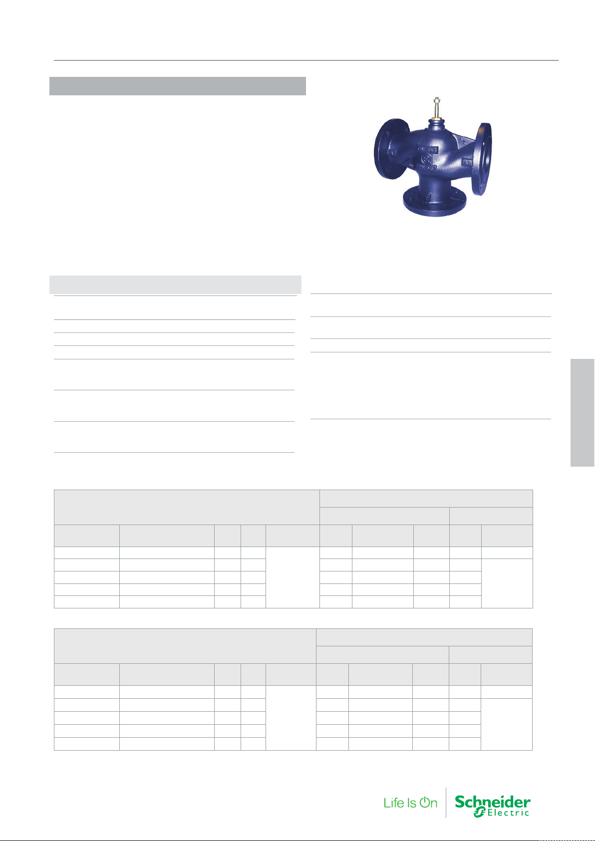
VG311F 65-150C
The VG311F...C is a large flanged general purpose valve suitable for
a wide range of mixing applications with hot or chilled water in heating cooling and air handling systems.
If the valve is used for media at temperatures below 0 °C, it should
be equipped with a stem heater to prevent ice formation on the valve
stem.
Specifications
Design 3-way plug mixing valve
stem up closed (A port/B-AB open)
Pressure class PN 16
Connection Flange according ISO 7005-2
Rangeability (Kvs/Kv
Flow characteristics
A – AB Equal Percentage
B – AB Linear
Stroke
DN65 25 mm
DN80…150 45 mm
Leakage
A – AB < 0.03% of Kvs
B – AB < 2% of Kvs
) > 50
min.
4. Globe Valves
∆Pm (mixing) 200 kPa, water
∆Pm (diverting) 60 kPa, water
Max. temperature of medium 150 °C
Min. temperature of medium -10 °C
Max. Glycol concentration 50%
Main Construction Materials
Body Grey Cast iron (GJL 250)
Stem Stainless steel (AISI 303)
Plug (DN65…DN100) Brass (CW614)
Plug (DN125…DN150) Bronze (CB491K UNI EN 1982)
Seat Grey Cast iron (EN JL 1040)
Stem Packing EPDM
4. Globe Valves
Mixing Applications
VG311F...C
Part Number Type Designation DN Kvs Rangeability M800
VG311F-65C VG311F-65C 63M SU00 65 63
VG311F-80C VG311F-80C 100M SU00 80 100 160 240 570 140
VG311F-100C VG311F-100C- 130M SU00 100 130 100 150 370 80
VG311F-125C VG311F-125C 200M SU00 125 200 60 90 230 50
VG311F-150C VG311F-150C 300M SU00 150 300 40 50 160 35
>50
Max Close-off Pressure ΔPC (kPa)
Non-spring Return Actuators Spring Return
M1500 / MV15B
(1500N)
240 400 850 220 290
M3000 M700 MG900 SR
Diverting Applications
VG311F...C
Part Number Type Designation DN Kvs Rangeability M800
VG311F-65C VG311F-65C 63M SU00 65 63
VG311F-80C VG311F-80C 100M SU00 80 100 53 80 190 45
VG311F-100C VG311F-100C- 130M SU00 100 130 33 50 125 25
VG311F-125C VG311F-125C 200M SU00 125 200 20 30 76 16
VG311F-150C VG311F-150C 300M SU00 150 300 13 16 55 12
∆PC = Maximum allowed pressure drop across a closed valve (that the nominal force of the actuator will open or close against).
>50
Max Close-off Pressure ΔPC (kPa)
Non-spring Return Actuators Spring Return
M1500 / MV15B
(1500N)
80 135 285 75 85
M3000 M700 MG900 SR
-
-
F-27878-6 49
Page 50

Actuators
5. Globe Valve
50 F-27878-6
Page 51
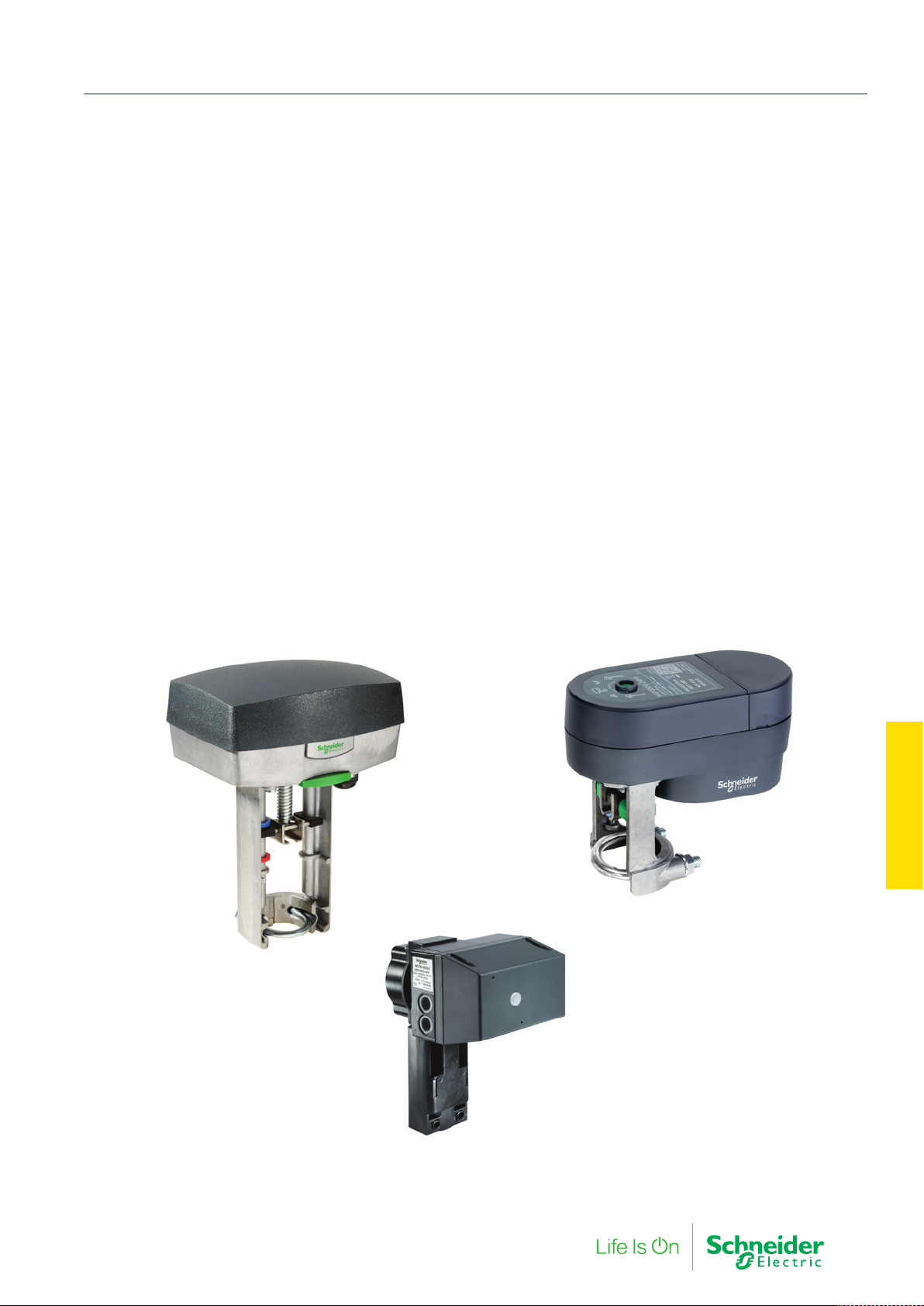
5. Globe Valve Actuators
Fine hydronic control in a globe valve is achieved from precise
positioning actuators.
Forta actuators provide superb positioning accuracy across a
broad range of valves and also accept multiple modulating input
signals, as well as 3-position floating control. Running speed is fast
and fixed to a set value based on the valve stroke limits, enabling
simple tuning of control loops. Position feedback, manual override
and the ability to add auxiliary switches are other features possible
on globe valves actuators.
F-27878-6 51
Actuators
5. Globe Valve
Page 52
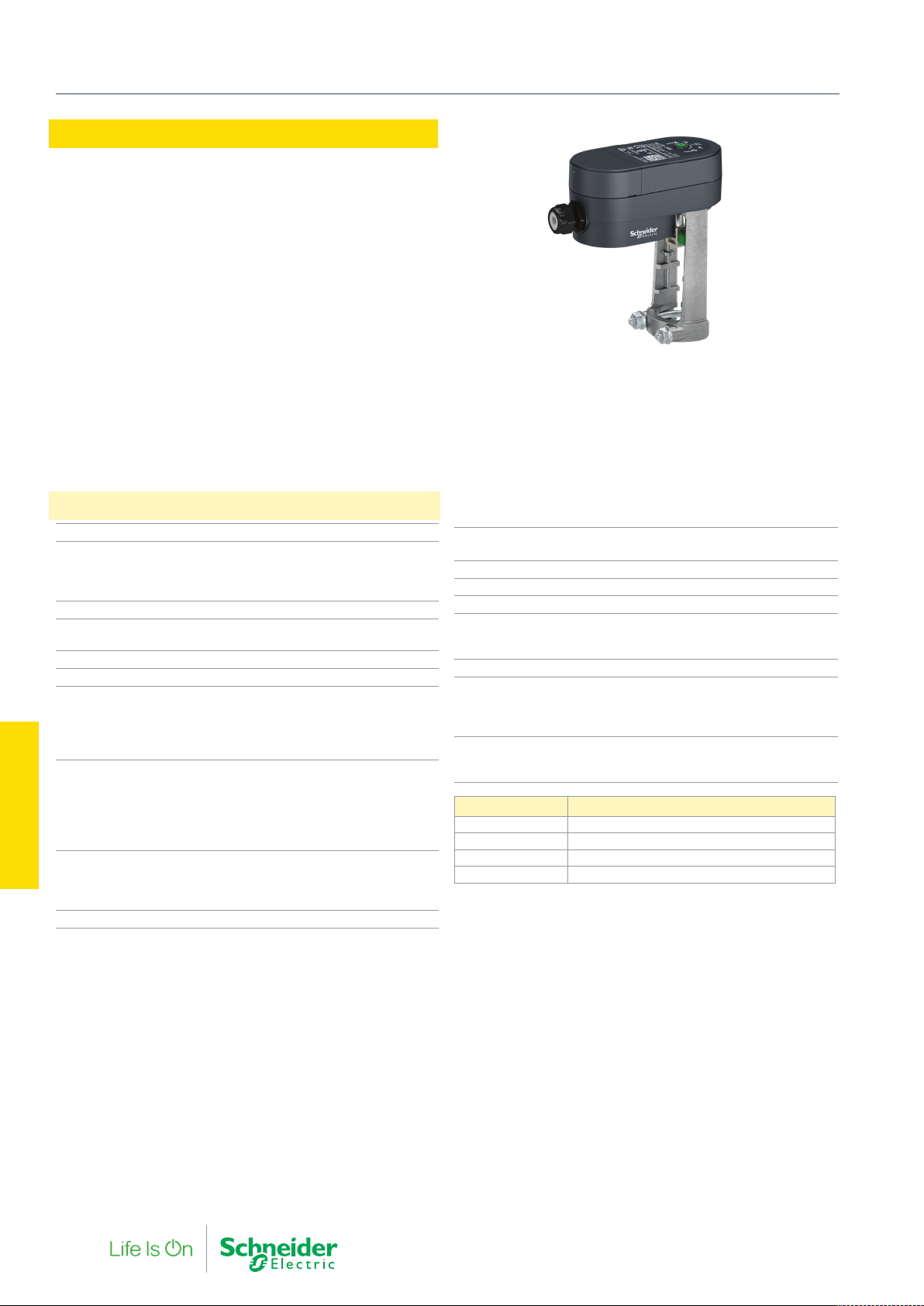
5. Globe Valve Actuators
MG350
The MG350 is a compact electro-mechanical actuator for controlling
2-way and 3-way Venta globe valves V241/V341, V211, V211T, V311,
and V311T. The MG350 actuators are primarily designed for applications where the demands on speed and thrust are relatively small.
• Stable force control with stall protection
• Dual 3-Point floating and 2-position control.
• Sink or source floating control
• High Resolution PCBA and motor transmission for fine valve
plug position and excellent flow control.
• LED status indication
– Tri-color LED for operation, calibration, and alarm
notification
• Removable terminal block and cable gland for ease of
installation.
Specifications
Supply voltage 24 Vac/Vdc ±20% 50/60 Hz
Power Consumption (50Hz)
Running: MG350-24 (F)
MG350-24 (M/MP/FP)
Holding (M/MP/FP)
Transformer sizing (same as power consumption)
Running Time 4 s/mm (Full stroke
Max. Stroke 21.5 mm
Force 350 N
Control (Floating/Digital)
Dependant upon wiring
3 wire Floating
2 Position on/off
Minimum input pulse
Control (Modulating)
Selectable input signals
MG350-24M
MG350-24MP
Actuators
5. Globe Valve
Impedance
Environment
Operating Temperature
Storage
Humidity max. 95%
24 Vac/Vdc or 0 V
0…10 Vdc, 2…10 Vdc
0…10 Vdc, 2…10 Vdc,
–5…+55 °C (for valve fluid
temperatures up to 130 °C)
5.2 VA (3.5 W)
7.2 VA (3.5 W)
1.2 VA
time = 80 sec)
NO or NC
100 msec
4…20mA
min. 100 kΩ
–40…+70 °C
Position Feedback
MG350-(24MP/-24FP)
Enclosure rating IP 53 (vertically mounted)
Sound power level max. 30 dBA
Weight (shipping) 0.36 kg
Material
Yoke
Housing
Manual Override 3 mm Hex
Position indication Red and blue position markers
Wiring entry
Cable Gland wire size
Conduit hole
Part Number Control
MG350-24M Modulating
MG350-24MP Modulating with feedback and alarms
MG350-24F Floating
MG350-24FP Floating with feedback and alarms
for hot and cold pipe indication
0…5 Vdc / 2…10 Vdc
(green position indicator for
closed valve)
min. 2.4 mm…max. 6.6 mm
Aluminum
PBT/PC
M20
52 F-27878-6
Page 53

MG350C
The MG350C is a compact electro-mechanical actuator for controlling the VG210 and VG310 2-way and 3-way linear globe valves. The
MG350C actuators are primarily designed for applications where the
demands on speed and thrust are relatively small.
• Stable force control with stall protection
• Hysteresis Control - Intelligent response to fluctuating control
signals, extending actuator life and better plant regulation
• High Resolution PCBA and motor transmission for fine valve
plug position and excellent flow control.
• Low power holding
• Auto adaptation to valve end stroke limits upon first power up
• LED status indication
– Tri-color LED for operation, calibration, and alarm
notification
• Removable terminal block and cable gland for ease
installation
5. Globe Valve Actuators
Specifications
Supply voltage 24 Vac/Vdc ±20% 50/60 Hz
Power Consumption (50Hz)
Running
MG350C-24F
MG350C-24M
Holding (Modulating only)
Transformer sizing (same as power consumption)
Running Time 8 s/mm (Full stroke time
Max. Stroke 16.5 mm
Nominal Force 350 N
Control (Floating/Digital)
Dependant upon wiring
3 wire Floating
2 Position on/off
Minimum input pulse
Control (Modulating)
Selectable input signals
Impedance
Environment
Operating Temperature
Storage
Humidity max . 95% RH (NC)
Enclosure rating IP 53 (vertically mounted)
0…10 Vdc, 2…10 Vdc
–5…+55 °C (for valve fluid
temperatures up to 130 °C)
5 VA (3.5 W)
7.2 VA (3.5 W)
1.2 VA
= 88 sec)
24 Vac/Vdc or 0 V
NO or NC
100 msec
min. 100 kΩ
–40…+70 °C
Sound power level max. 30 dBA
Weight (shipping) 0.36 kg
Material
Yoke
Material Housing (Covers)
Mechanical
Manual Override
Position indication Red and blue position markers
Wiring entry
Cable Gland wire size
Conduit hole
Part Number Control
MG350C-24M Modulating
MG350C-24F Floating
for hot and cold pipe indication
(green position indicator for
min. 2.4 mm…max. 6.6 mm
Aluminum
PBT/PC
3 mm Hex
closed valve)
M20
Actuators
5. Globe Valve
F-27878-6 53
Page 54
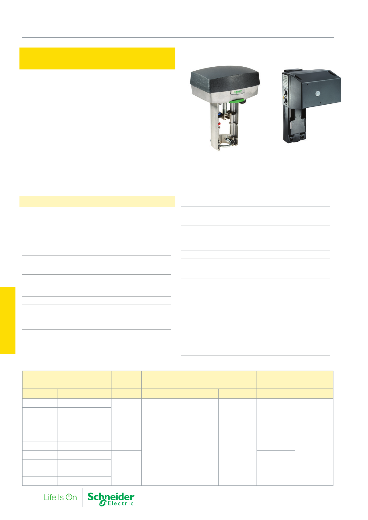
5. Globe Valve Actuators
Forta M310, M400, M800, M1500 and
M3000
The Forta is a family of actuators for the control of 2-way and 3-way
globe valves.
The Forta has a very fine resolution PCBA board which provides
good rangeability of the valve. The Software in the actuator calibrates the running time and S2 switch points to the valve stroke
limits. It may also be configured for different flow characteristics,
inverse signal or sequence control.
The U-bolt mounting makes for a very easy and quick installation.
The manual override allows the actuator to be overridden and valve
position adjusted without disconnecting the power supply.
Specifications
Supply Voltage
AC 24 Vac +25% / -35%, 50/60 Hz
DC 24 Vdc ±10%
Duty cycle Max. 20%/60 minutes
Full Stroke Runtime
Modulating (refer to table)
Increase/decrease 300s/60s
Analog Control Input
Selectable Voltages 0…10 V/ 2…10 V/
0…5 V/ 5…10 / 2…6 / 6…10
Impedance Min. 100 kΩ
Digital inputs VH-HC
Voltage across open input 24 Vac
Current through closed input 5 mA
S2 Output – Auxiliary end point switch (optional)
Type 2 x SPDT
Voltage 24 VAC
Load 4A (resistive) / 1A (inductive)
Actuators
Regulated Voltage Output, G1
5. Globe Valve
Voltage 16 Vdc ±0.3 V
Load 25 mA, shor t-circuit proof
M310, M400, M800, M1500 M3000
Position Feedback, Y
Voltage 2…10 V (0…100%)
Load 2 mA
Environment
Operating Temperature -10…+50 °C
Storage Temperature -10…+50 °C
Humidity Max. 90% RH
Enclosure rating IP 54
Wiring entry
Conduit connection 3 x M20 screwed
Cable gland 1 x 6..12 mm O/D, IP68
Standards
ElectroMagnetic Compatability [EMC] 2014/30/EU
Low voltage directive [LVD] 2014/35/EU
Restriction of Hazardous Substances [RoHS2] 2011/65/EC
Heat IEC 60068-2-2
Humidity IEC 60068-2-3
Cold IEC 60068-2-1
Vibration IEC 60068-2-6
Main Construction Materials
Housing Aluminium
Cover ABS/PC plastic
Color (M310, M400, M800, M1500) Aluminium/Grey
Color (M3000) Black/Grey
Forta Actuators Force
Part Number Description N 9-25 mm 25-32 mm 32-51 mm VA
880 0210 030 M310
880 0211 030 M310 S2
880 0230 030 M400
880 0231 030 M400 S2
880 0310 030 M800
880 0311 030 M800 S2
880 0450 000 M1500
880 0451 000 M1500 S2
880 0500 000 M3000
880 0510 000 M3000 S2
300 15s 20s
400 60s 60s 7
800
1500 15
3000 14-40s 40-50s 50-80s 25
Modulating control
Running time / stroke
-
15s 20s 30s
Avg. power
consumption
6
10
Transformer
sizing
30
50
54 F-27878-6
Page 55
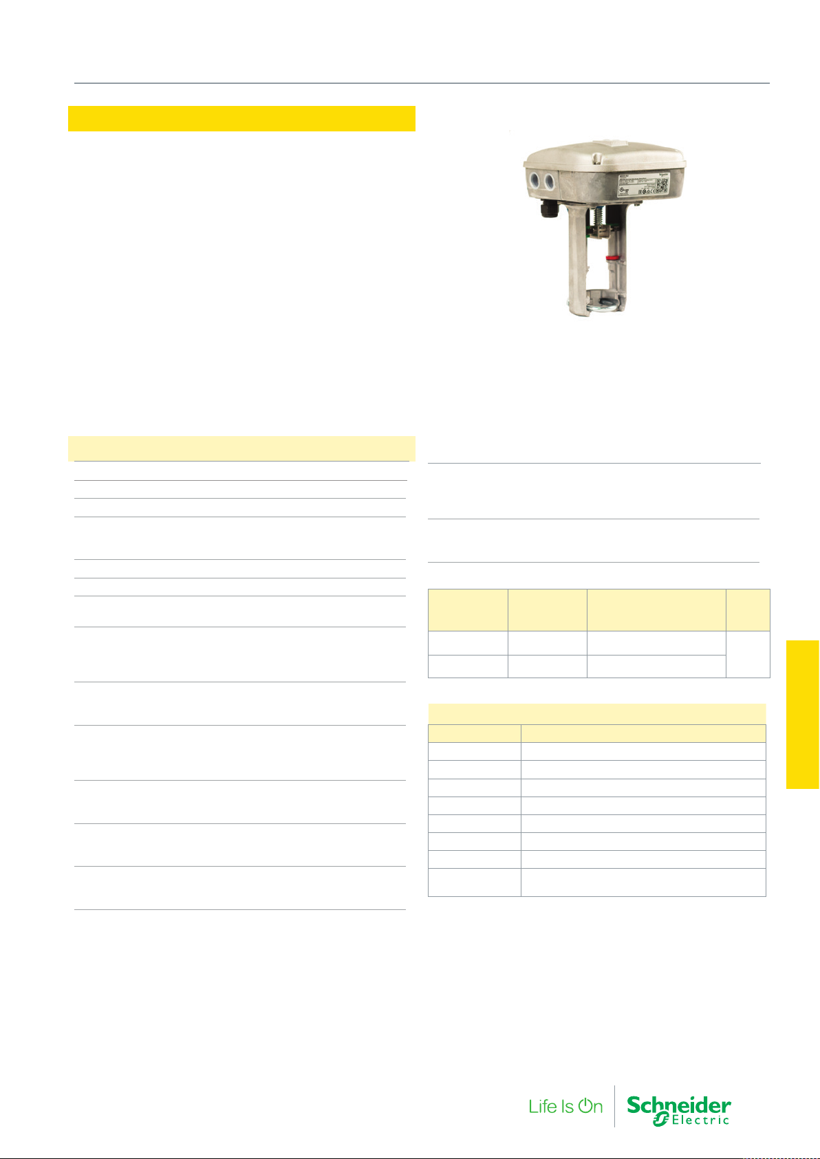
Forta MG900 SR
The Forta MG900 SR is a spring return actuator for the control of
linear globe valves.
The Manual override is operated by a hex key and can be locked into
position for commissioning.
Regenerative Braking is used to control the actuator closing speed
when the actuator is driven under the spring return force.
Specifications
Supply voltage 24 Vac +25% / -30%, 50/60 Hz
Power consumption Average 30 VA
Transformer sizing 50 VA
Spring return close off time at power failure
20 mm stroke Less than 50 seconds
32 mm stroke Less than 95 seconds
Stroke Range 9…30 mm
Thrust 900 N
Duty cycle Max. 20%/60 minutes
(and 80%/ 60 min.) for half load / amb. temp
Running Time
Modulating 10…25 mm (0.39…1 in.) 15s
Modulating 25…32 mm (1…1.26 in.) 20s
Increase/decrease 300s/60s
Analog input
Voltage 0…10 V / 2…10 V / 0…5V /
5…10 / 2…6 / 6…10
Digital inputs VH–VC
Voltage across open input 24 Vac
Current through closed input 5 mA
Pulse time Min. 20 ms
Output, G1
Voltage 16 Vdc / 20 Vdc ±0.3 V
Load 25 mA, shor t-circuit proof
Output, Y
Voltage 2…10 V (0…100%)
Load 2 mA
Wiring Entry
Conduit connection 4 x M20 capped holes
Cable gland 1 x 6..12 mm O/D, IP68
5. Globe Valve Actuators
Environment
Operating Temperature -10…50 °C
Storage Temperature -10…50 °C
Humidity Max. 90% RH
Main Construction Materials
Housing Aluminium
Cover Aluminium
Part Number
MG900-SU Stem Up MG900 SRU-24FM T54 00
MG900-SD Stem Down MG900 SRD-24FM T54 00
Spring Return
Function
Type Designation
Accessories
Part Number Description
880 0104 000 S2 auxiliary end point switches
AV-821 Linkage kit to VB-7000 valves
AV-822 Linkage kit to VB-8000 valves
880 0109 000 Yoke Heater
MG900-SU-PCB Circuit board for MG900 SRU
MG900-SD-PCB Circuit board for MG900 SRD
880 0124 000 L2SV linkage kit to VZ and MZ Satchwell Valves.
880 0129 000 Linkage - M30 x 1.5, Spirax Sarco KE, KL, KF,
DN15…100
IP
Rating
54
Actuators
5. Globe Valve
F-27878-6 55
Page 56
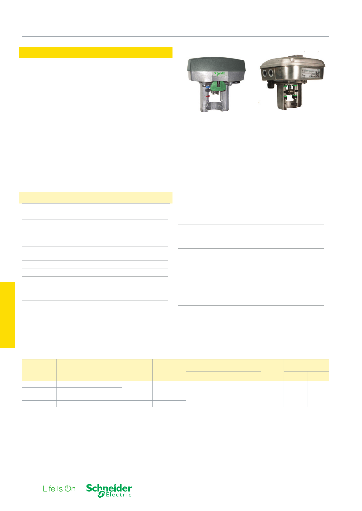
5. Globe Valve Actuators
Forta MG600C, MG600C-SR
The MG600C and MG600C-SRU/SRD are short yoke Forta
actuators designed for use with the VG210R and VG310R valves.
Spring return and Non-spring return versions with the full Forta functionality and precision control: Flexible control configuration, floating
or modulating, sequencing, position feedback and flow curve adap-
tation (EQ to Lin).
• Brushless DC motors and a high resolution control board
allow a very fine fluid control in globe valves.
• Working range and end point switches adjust automatically to
valve stroke.
• Firmware calibrates consistent running time regardless of
valve stroke.
• On power loss the spring return mechanism drives the
motor, generating power to control braking speed, avoiding
mechanical stress and system water hammer.
• Available in spring return stem up or spring return stem down
and either IP54 or rooftop IP65 enclosures.
Specifications
Supply voltage 24 Vac +25% / -35%, 50/60 Hz
Duty cycle Max. 20%/60 minutes
Analogue control input
Selectable Voltages 0…10 V / 2…10 V / 0…5V /
5…10 / 2…6 / 6…10
Impedance Min. 100 kΩ
Digital control input (3-point floating)
Voltage across open input 24 Vac
Current through closed input 5 mA
Minimum Pulse Time 20 ms
S2 Output – Auxiliary end point switch where fitted
Type 2 x SPDT
Voltage 24 Vac
Load 4A (resistive) / 1A (inductive)
MG600C MG600C-SR
• Configurable for either a 3-point increase/decrease signal or
various modulating control signals including sequencing.
• U-Bolt connection allows direct mounting without any
mounting kit or special tools.
Position feedback (Y)
Voltage 2…10 V (0…100%)
Load 2 mA
Wiring entry
Conduit connection 600C 3 x M20 screwed
600C-SR 4 x M20 screwed
Cable gland 1 x 6..12 mm O/D, IP68
Environment
Operating Temperature -10…+50 °C
Storage -10…+50 °C
Humidity Max. 90% RH
Enclosure rating IP 54
Main Construction Materials
Housing Aluminium
Cover ABS/PC plastic
Color Aluminium/Grey
Actuators
5. Globe Valve
Part Number Designation SR Function VG210R /
MG600C MG600C-24FM T54 00
MG600C-S MG600C-24FMS T54 00
MG600C-SRU MG600C SRU-24FM T54 00 Stem Up A-AB Closed
MG600C-SRD MG600C SRD-24FM T54 00 Stem Down A-AB Open
The MG600C(-SR) will not connect on to Satchwell or the 20 mm stroked Venta valves. ex. V211, V241
56 F-27878-6
- - 60s
VG310R
function on
SR operation
Running time Transf.
Modulating Increase/Decrease (running) (rest)
300s/60s
15s 50 VA 21W 7W
sizing
30 VA 4W 3W
Power
consumption
Page 57
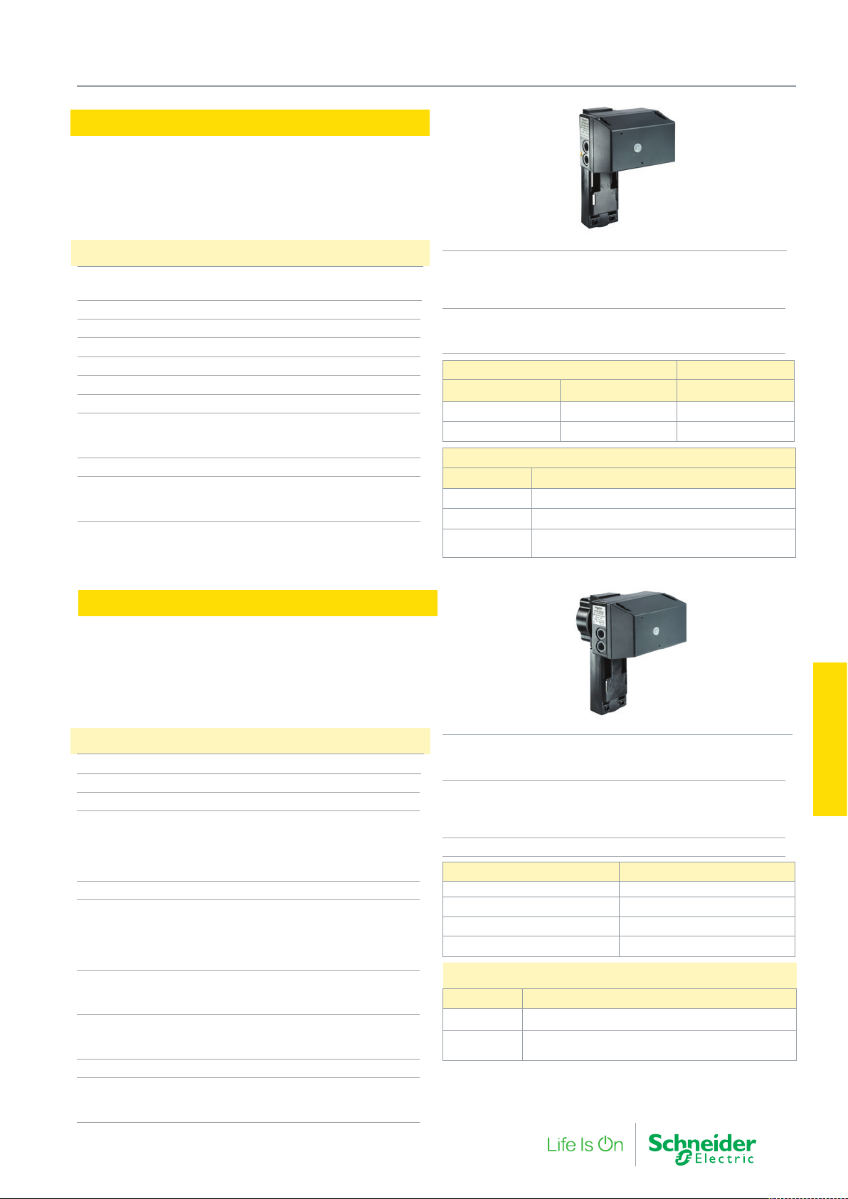
MV15B
The MV15B is a powerful 3-point floating actuator for the control of
2-way and 3-way globe valves, available in both 24 Vac and 230 Vac
versions. The actuator self adjusts to the stroke of whatever valve
it is connected to. The U-bolt mounting makes for a very easy and
quick installation. A manual override is standard on all models.
5. Globe Valve Actuators
Specifications
Supply voltage 24 Vac ±10%, 50/60 Hz
230 Vac ±10%, 50/60 Hz
Power consumption 12 VA
Transformer sizing 15 VA
Running speed 0.75 mm/s
Running time for 20 mm 27s
Stroke Range 9…52 mm
Thrust 1500 N
Environment
Operating Temperature 15…50 °C
Storage Temperature -25…+65 °C
Enclosure rating IP 55
Wiring Entry
Conduit connection 2 x PG13.5 capped hole
Cable gland 1 x 6..12 mm O/D
Forta M700 - Spring Return
The Forta M700 is a spring return actuator for control of longer
stroked and larger size globe valves. It utilises the same flexible
functionality as in the Forta non-spring return actuators so it has the
same capability for self-adapting to the valve stroke, and the same
flexibility in set-up configuration. The U-bolt mounting makes for
quick installation. Manual override is standard on all models.
Main Construction Materials
Housing Aluminium
Cover ABS plastic
Color Black/Red
Optional auxiliary travel switch S2-MV15B
Type SPDT 10A (resistive), 3A (inductive)
Capacity 250 V
MV15B actuators Power supply
Part Number Description Vac +10%/ -10%
880 0460 000 MV15B-230 230
880 0462 000 MV15B-24 24
MV15B accessories & linkage kits
Part Number Description
880 0126 000 Linkage M700-Satchwell L7SV
880 0469 000 Switch S2-MV15B
880 0109 000
Forta Yoke Heater for amb. temp -10 °C, media temp
-8 °C
Specifications
Supply voltage 24 Vac +25% / -30%, 50/60 Hz
Power consumption Average 30 VA
Transformer sizing 50 VA
Spring return close off time at power failure
20 mm stroke Less than 50 seconds
45 mm stroke Less than 95 seconds
Stroke Range 9…52 mm
Thrust 700 N
Duty cycle Max. 20%/60 minutes
Running Time
Modulating 10…25 mm 15s
Modulating 25…32 mm 20s
Modulating 10…52 mm 30s
Increase/decrease 300s/60s
Analog input
Voltage 0…10 V / 2…10 V / 0…5V / 5…10 V / 2…6V / 6…10 V
Impedance Min. 100 kΩ
Digital inputs VH–VC
Voltage across open input 24 Vac
Current through closed input 5 mA
Pulse time Min. 20 ms
Position feedback
Voltage 2…10 V (0…100%)
Load 2 mA
F-27878-6 57
Wiring Entry
Conduit connection 2 x PG13.5 capped hole
Cable gland 1 x 6..12 mm O/D
Environment
Operating Temperature -10…50 °C
Storage Temperature -10…50 °C
Humidity Max. 90% RH
Enclosure rating IP 54
Part Number Description
880 0430 000 M700-SRSU
880 0431 000 M700-S2-SRSU
880 0440 000 M700-SRSD
880 0441 000 M700-S2-SRSD
Accessories
Part Number Description
880 0126 000 Linkage M700-Satchwell L7SV
880 0109 000 Forta Yoke Heater for amb. temp -10 °C, media temp -8 °C
Key:
S2- Auxiliary end point switch
SRSU - spring return stem up
SRSD - spring return stem down
L7SV - Satchwell linkage to VZ and MZ valves
Actuators
5. Globe Valve
Page 58

5. Globe Valve Actuators
Forta M400, M800, M1500, MG600C Electrical Accessories
Part Number Description
880 0104 000 S2 – 2 x SPDT Axillary End Point Switches (24 Vac 4A AC-1)
880 0109 000 Forta Yoke Heater for amb. temp -10 °C, media temp -8 °C
Forta M400, M800, M1500 Linkage kits to other valves
Part Number Description
880 0124 000 Linkage Forta-Satchwell L2SV: VSF-MJF-MZ, VZ-MZF- VZF
880 0116 000 Linkage Forta-Honeywell M6 and 6.25 mm (1/4”) stem
880 0118 000 Linkage Forta-Siemens
880 0125 000 Linkage Forta-Danfoss
880 0129 000
880 0128 000 Linkage – Controlli Flanged Valves with M40 threaded bonnet VBG, SS, DS, VSS, VBA, 3V, VMS VSG, VMB16, SSGA
880 0135 000
880 0252 000 Linkage TAC V298, DN15
880 0253 000 Linkage kit for old TAC DN15 valves -V282/ V294/ V384/ V386/ V394
880 0130 000 V321 DN65…DN100 to Forta (convert from M16 actuator)
AV-821 Forta to VB-7000 valves (Siebe/TAC)
AV-822 Forta to VB-8000/VB-9000 valves (Siebe / TAC)
AV-823 Stem extension for VG210R/VG310R
Linkage Forta-Spirax Sarco (M30 x1.5 :KE, KF, and KL; DN15…100)
Linkage – Controlli threaded valves with M30 bonnet types: VSB, VMB, VSB_F, VMB_F
Linkage Satchwell VZ 7*** and MZ 7*** series
Regin/Osby: NTVS / GTRS / GTVS, 2SAS / 2SBS, MTVS / MTRS, MRT and FRS
Actuators
5. Globe Valve
58 F-27878-6
Page 59

5. Globe Valve Actuators
F-27878-6 59
Actuators
5. Globe Valve
Page 60

Actuators
6. Ball Valve and
60 F-27878-6
Page 61
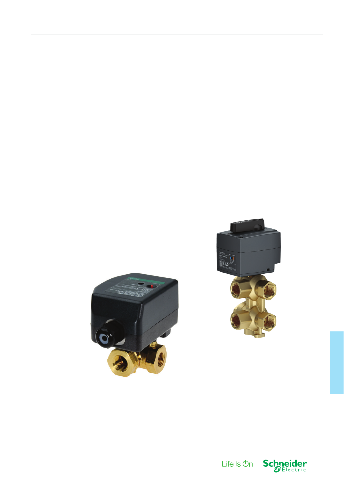
6. Ball Valves and Actuators
Ball Valves provide reliable, high static pressure control of fluids.
The Schneider Electric VB210R / VB310R / VB601R range of control
valves provide excellent EQ proportional flow control with a full
complement of electrical actuators.
The VB200R / VB300R types are a full flow design without any
restrictive EQ characterisation disc and are ideal for isolation or
change over in two-position control.
F-27878-6 61
Actuators
6. Ball Valve and
Page 62
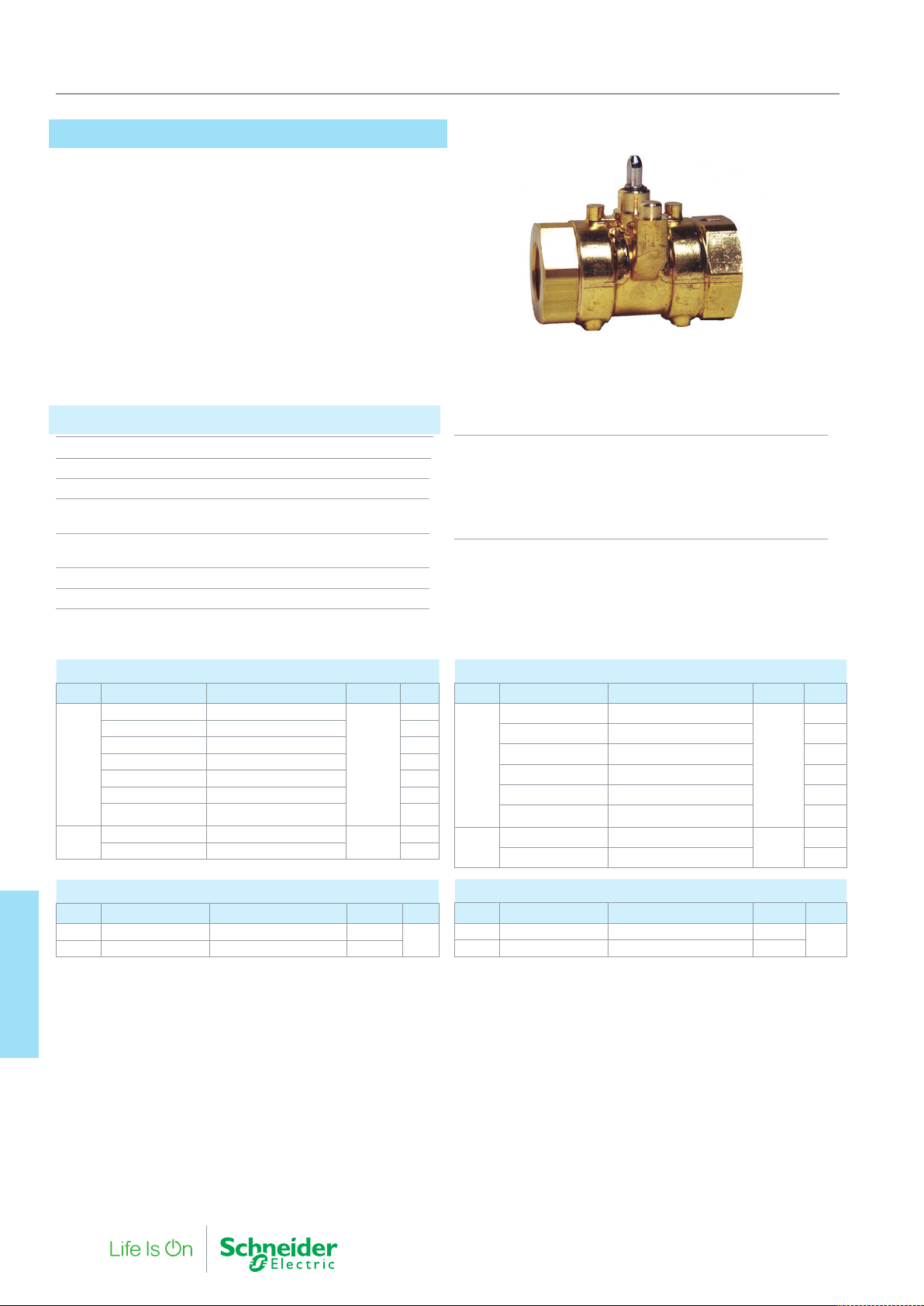
6. Ball Valves and Actuators
VB210R, VB200R & VB310R, VB300R
These VB range of ball valves utilise a low friction packing design
around the ball which enables a low torque and compact motor to
be used in the actuator.
The VB210R and VB310R ball valves variants incorporate a flow
characterizing insert to providing an equal percentage flow
characteris tic with high rangeability.
These valves are suitable for control of hot or chilled water applications.
Specifications
Servicea Hot and chilled water, up to 60% glycol
System Static Pressure Limit PN40
Media Temperature Limits -7…120 °C
Close-off Pressureb 895 kPa 2-way;
480 kPa, 3-way
∆Pm 205 kPa normal operation,
135 kPa psi quiet operation
Seat Leakagec ANSI class IV (0.01%)
End Connections Rp threaded
VB210R 2-way Control Valves
Size Part Number Type Designation Thread kvs
VB210R-15BS01 VB210R-15BS 0.25T 00
VB210R-15BS03 VB210R-15BS 0.6T 00 0.6
VB210R-15BS04 VB210R-15BS 1.0T 00 1.0
VB210R-15BS05 VB210R-15BS 1.8T 00 1.8
DN15
VB210R-15BS07 VB210R-15BS 3.0T 00 3.0
VB210R-15BS08 VB210R-15BS 4.0T 00 4.0
VB210R-15BS09 VB210R-15BS 6.3T 00 6.3
VB210R-20BS08 VB210R-20BS 4.0T 00
20
mm
VB210R-20BS09 VB210R-20BS 6.3T 00 6.3
Rp 1/2
Rp 3/4
0.25
4.0
Material
Body Material Forged UNC 37700 brass
Stem Material Stainless steel
anti-blow out stem with dual Viton™ o-rings
Ball Material 304 Stainless steel
Seat Material PTFE
Characterized Insert Glass-filled PEEK
a. Not rated for steam service.
b. Close-off is defined as the maximum allowable pressure drop to which a valve may be
subjected while fully closed.
c. Seat Leakage in normal direction of flow only
VB310R 3-way Control Valves
Size Part No. Type Designation Thread kvs
VB310R-15BS03 VB310R-15BS 0.52T 00
VB310R-15BS04 VB310R-15BS 0.86T 00 0.86
VB310R-15BS05 VB310R-15BS05 1.6T 00 1.6
DN15
VB310R-15BS07 VB310R-15BS07 2.5T 00 2.5
VB310R-15BS08 VB310R-15BS 4.0T 00 4.0
VB310R-15BS09 VB310R-15BS 6.3T 00 6.3
VB310R-20BS08 VB310R-20BS 4.0T 00
DN20
VB310R-20BS09 VB310R-20BS 6.3T 00 6.3
Rp 1/2
Rp 3/4
0.52
4.0
VB200R 2-way Full Port Valves
Size Part Number Type Designation Thread kvs
DN15 VB200R-15BS VB200R-15BS 8.7T 00 Rp 1/2
DN20 VB200R-20BS VB200R-20BS 8.7T 00 Rp 3/4
8.7
VB300R 3-way Full Port Valves
Size Part No. Type Designation Thread kvs
DN15 VB300R-15BS VB300R-15BS 8.7T 00 Rp 1/2
DN20 VB300R-20BS VB300R-20BS 8.7T 00 Rp 3/4
Actuators
6. Ball Valve and
62 F-27878-6
8.7
Page 63
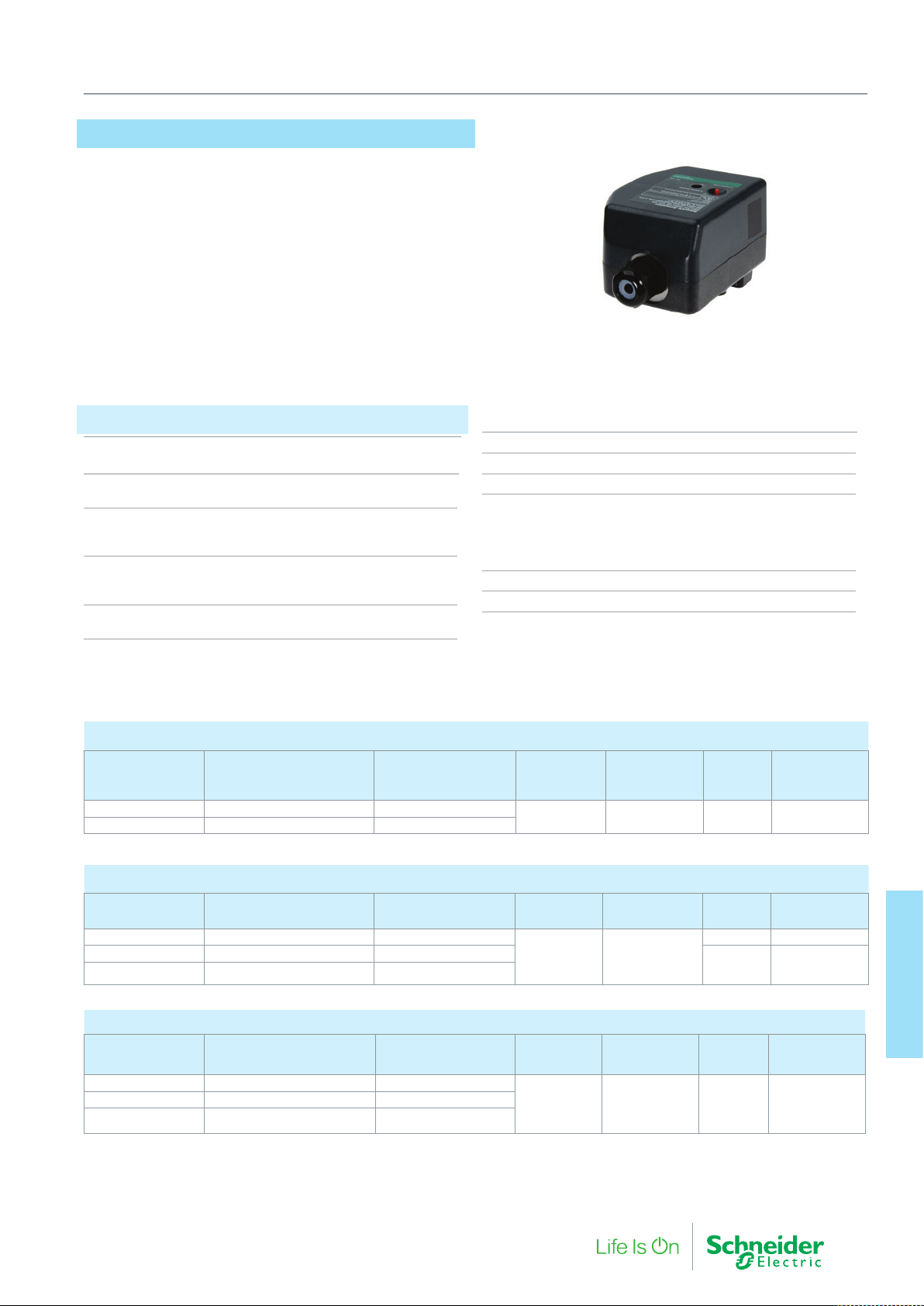
MB3, MB6
The MB3 and MB6 are compact actuators for the VB210R, VB310R,
VB200R and VB300R.
A ‘pop top’ connection between the valve and actuator provides a
fast and easy installation.
Actuators are available in both spring return and non-spring return
versions for floating, proportional and 2-position control.
Specifications
Supply Voltage
Floating and Modulating 24 Vac +25%, -15% @ 50/60 Hz.
Two-Position 24 Vac 50/60, (+25%, -15%).
24 Vdc (+/-20%)
Manual Operation
Floating / Modulation Hand lever
Two-position Hex Key 3.96 mm (5/32”)
Proportional Control
(Field Selectable) 0...10 V, 2..10 V, 0..5 V, 5..10 V,
4..20 mA Direct or reverse acting
Main Construction Materials Thermoplastic base and cover.
Approved for use in air plenums.
6. Ball Valves and Actuators
Electrical Connection Terminal Block
Cable Gland (M20) 5…9 mm O/D
Shipping & Storage Temp. Limits -40…76 °C
Environment (at media temp. limits)
Operating Temperature
Floating 0…60 °C
Proportional 0…60 °C
Two-Position 0…76 °C
Humidity 5…95% relative humidity, non-condensing
Enclosure rating (Horizontal and Vertical Mounting) IP31
Two-Position Actuators
Part Number Type Designation
MB6-SO-24T MB6-SRO-24T T31 00 Normally Open
MB6-SC-24T MB6-SRC-24T T31 00 Normally Closed
Spring Return Action
(Valve Normal Position)
Stroke Time,
sec. 50/60 Hz
50 35 3.5/1.8 2.3/1.6 W
Three Point Floating Actuators (Increase/Decrease)
Part Number Type Designation
MB3-24F MB3-24F T31 00 None
MB3-SO-24F MB3-SRO-24F T31 00 Normally Open
MB3-SC-24F MB3-SRC-24F T31 00 Normally Closed
* Size transformer for each spring actuators at 7VA
Spring Return Action
(Valve Normal Position)
Stroke Time,
sec. 50/60 Hz
135 180
Proportional Actuators (0…10 V, 2..10 V, 0…5V, 5…10 V, 4…20 mA)
Part Number Type Designation
MB3-24M MB3-24M T31 00 None
MB3-SO-24M MB3-SRO-24M T31 00 Normally Open
MB3-SC-24M MB3-SRC-24M T31 00 Normally Closed
* Size transformer for each spring actuators at 7VA
Spring Return Action
(Valve Normal Position)
Stroke Time,
sec. 50/60 Hz
135 166 4.5* 2.0 W
Spring Return
Time, sec. 50/60
Hz
Time-out Delay,
sec. 50/60 Hz
Time-out Delay,
sec. 50/60 Hz
VA @ 24 V
ac/dc
VA
4.5 2.0 W
4.5* 2.0 W
VA
Power
Consumption
ac/dc
Power
Consumption
Power
Consumption
Actuators
6. Ball Valve and
F-27878-6 63
Page 64
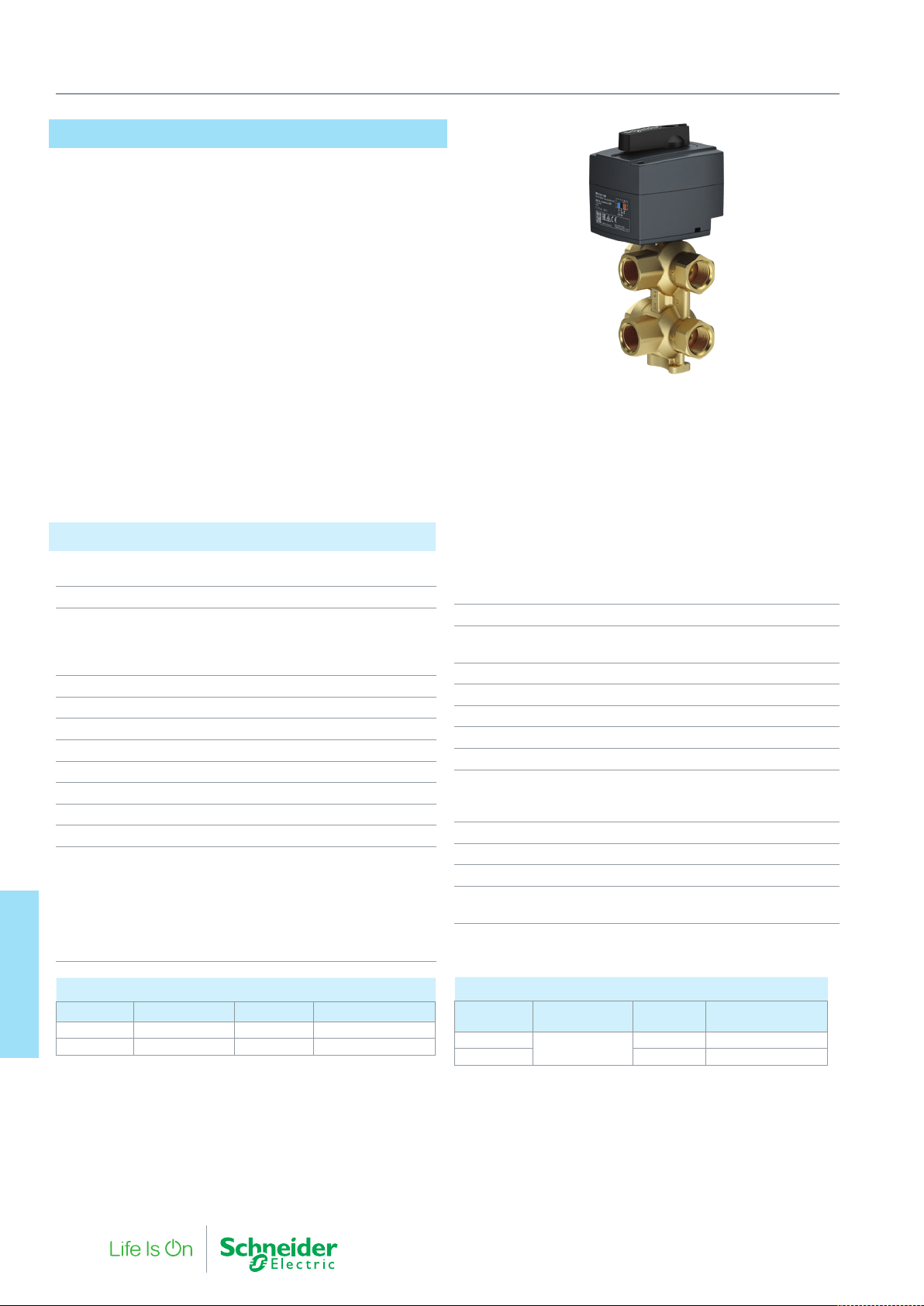
6. Ball Valves and Actuators
VB601R Motorized 6-port Ball Valve
The VB601R is a 6-port motorized ball valve that performs a diverting
function between two water circuits in 4-pipe changeover system.
The VB601R valve will switch between heating and cooling with the
addition of the SmartX MB10 two-position rotary actuator.
Flow regulation is provided from an additional SmartX PIBCV valve
and actuator. This provides the additional benefit of having a balanced energy efficient solution with superb proportional control.
A single on/off control signal to the 6-por t diverting valve actuator
determines the direction of flow through the valve. Changing the
control signal will rotate the actuator and switch the supply ports
between heating and cooling or vice versa. During the 6-port valve
motorization, the valve rotates through a mid point with all ports
isolated and with no possibility to cross connect and mix the heating
and cooling circuits.
• No cross-flow between supply circuits.
• Single on/off control signal to changeoversupply circuits.
• Visual indication of actual valve position.
• Silent and reliable operation.
• Maintenance free.
• Teflon seal and polished chrome valve ball to prevent valve
sticking.
• Manual override.
Specifications
Valve
DN 15 20
Diff Pressure 3.6 kPa
Kvs 2.4 m3/h 4.3 m3/h
Pressure Class, PN 16 16
Medium Temp. 0 ... 90 °C
Shut off 800 kPa
Valve neck Quick fix connection
Connection Inter nal thread Rp 1/2 ISO7/1
Certifications PED directive 97/23/EC (Art. 3§3)
Weight 1140 g
Main Construction
Materials: Body
and connection
Ball
Stem
Seals
O-ring
VB601R Valve bodies
Actuators
6. Ball Valve and
DN Kvs (m3/h) Connection Part Number
15 2.4 Rp 1/2 VB601R-15B
20 4.7 Rp 3/4 VB601R-20B
at Qnom of 450 l/h
DN15-STD Flow
SmartX PIBCV
14 kPa
Qnom of 900 l/h
DN20-STD Flow
SmartX PIBCV
CW 602 N (DZR Brass)
CW 614 N Chrome plated
CW 614 N Nickel plated
P.T.F.E. (TEFLON)
70 EPDM 281
Actuator
Power supply 24 AC ± 20% V
Operating power
consumption
Frequency 50/60 Hz
Running speed 80 sec/90°
Control input 2-point
Operating torque 10 Nm
Rotation angle 90 °
Environment
Operating Temperature
Storage / transp. temp
Protection Class (EN 60730-1) II according
Enclosure rating IP42
Weight 405 g
Connection cable
(halogen free)
MB10 Actuators
Supply
voltage (V)
24 AC
24 AC 10 MB10-24T-10M
Speed (s / 90°)
80
Cable
length (m)
1.5 MB10-24T
Part Number
5 VA (only
when running)
0…55 °C
−10…80 °C
1.5 m
3×0.5 mm
2
64 F-27878-6
Page 65

Notes
6. Ball Valves and Actuators
F-27878-6 65
Actuators
6. Ball Valve and
Page 66
Actuators
7. Buttery Valves and
66 F-27878-6
Page 67
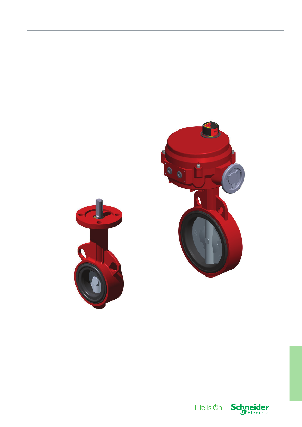
7. Butterfly Valves and Actuators
Butterfly Valves are the ideal choice of product for isolation (on/
off control) where needed within a plants heating system. The
full range of Schneider Electric products can be electrically or
manually operated.
F-27878-6 67
Actuators
7. Buttery Valves and
Page 68
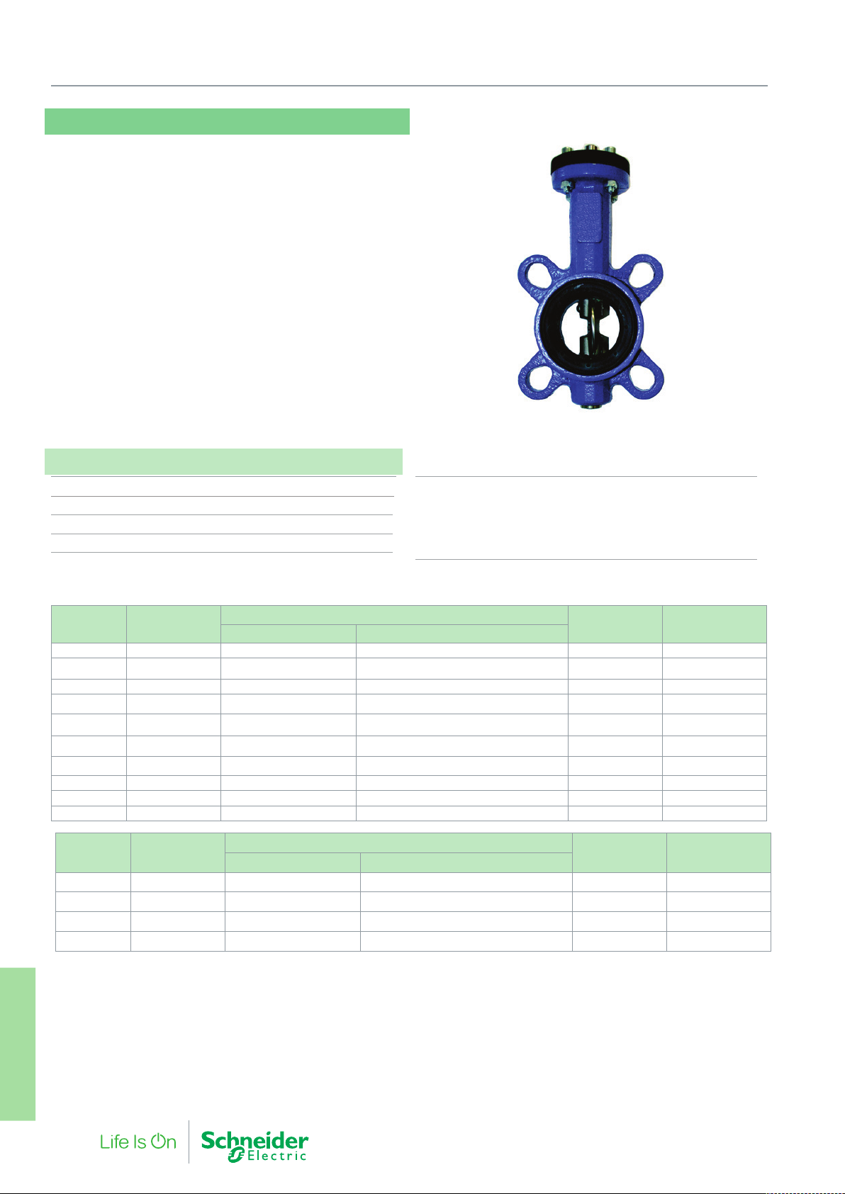
7. Butterfly Valves and Actuators
VF208W 25-200NS & 100-200NZ
The VF208W is a new generation butterfly valve for the isolation and
control of water for HVAC systems such as boiler isolation or heat pump
change over from cooling to heating. The butterfly valves have elongated
wafer type eyelets for fitment between flanges
• Energy saving: EPDM soft seats provide tight shut off and zero
leakage (complete insulation possible according to German
energy saving order, EnEV)
• Approved for use with drinking water DN25-80 (DVGW)
• Maintenance free, double sealing of stem, centrical disc bearing
• Good flow control characteristics
• Integrated dew point barrier
• No linkage kits required
Specifications
Pressure Class PN 16
Leakage (EN 12266-1) Tight, (Leakage Rate A)
Temperature Range -10 °C…+100 °C
Max glycol concentration 50%
Size Kv
DN25 26 VF208W-25NS VF208W-25NS 26E B00 600 MF20
DN32 26.5 VF208W-32NS VF208W-32NS 26E B00 600 MF20
DN40 50 VF208W-40NS VF208W-40NS 50E B00 600 MF20
DN50 115 VF208W-50NS VF208W-50NS 115E B00 600 MF20
DN65 260 VF208W-65NS VF208W-65NS 260E B00 600 MF20
DN80 375 VF208W-80NS VF208W-80NS 375E B00 600 MF20
DN100 760 VF208W-100NS VF208W-100NS 760E B00 600 MF20
DN125 1,025 VF208W-125NS VF208W-125NS 1025E B00 600 MF40
DN150 1,790 VF208W-150NS VF208W-150NS 1790E B00 300 MF40
DN200 3450 VF208W-200NS VF208W 200NS 3450E B00 300 MF40
Size Kv
DN100 760 VF208W-100NZ VF208W 100NZ 760E B00 600 MF20
DN125 1,025 VF208W-125NZ VF208W 125NZ 1025E B00 600 MF40
DN150 1,790 VF208W-150NZ VF208W 150NZ 1790E B00 300 MF40
DN200 3450 VF208W-200NZ VF208W 200NZ 3450E B00 300 MF40
Contact Product Management for larger sizes.
Stainless Steel Disc
Part Number Full Type Designation
Nodular Iron Disc
Part Number Full Type Designation
Main Construction Materials
Body Nodular Iron (EN-JS1030)
Lining EPDM
Disc DN25-80: 1.4581 (AISI316)
with zinc-lamella coating DN100-200: (EN-JS1030)
Stem 1.4021-QT
Max ΔP (kPa) Actuator
Max ΔP (kPa) Actuator
Actuators
7. Buttery Valves and
68 F-27878-6
Page 69
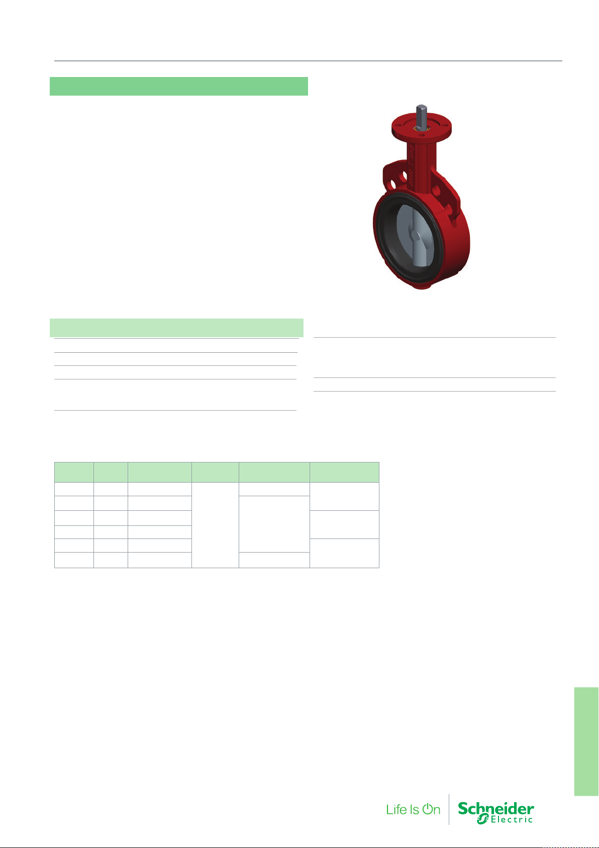
VF299W-250…500CN
The VF299W is a general purpose, large butterfly valve with an
undercut disc for low actuator torque.
• Wafer lugs for PN6, PN10 and PN16 pattern flanges
• The EPDM soft-seat provides a tight close off with low torque
actuator
• Nylon 11 disc for compatibility with many media types including
sea water
• Manual adjustment through hand lever, gearbox
7. Butterfly Valves and Actuators
Specifications
Pressure Class PN 16
Leakage (EN 12266-1) Gas tight, (Leak Rate A)
Temperature Range -29 °C…121 °C
Fluids Hot and cold water with
50% Glycol vol. max.
Well water, Sea water
Size Kvs Part Number
DN250 4670 VF299W-250CN
DN300 6946 VF299W-300CN
DN350 9063 VF299W-350CN
DN400 12004 VF299W-400CN
DN450 14804
DN500 19212 VF299W-500CN MF700
VF299W-450CN
Max ΔP
(kPa)
350
Actuator Gear operator
MF200
MF550/700
Main Construction Materials
Body ASTM A 126 ≈ GG25
Primary and Secondary seal, seat EPDM
Disc GGG40 Nylon11 coated
Stem 1.4405-QT
917 0300 000
917 0400 000
917 0500 000
F-27878-6 69
Actuators
7. Buttery Valves and
Page 70
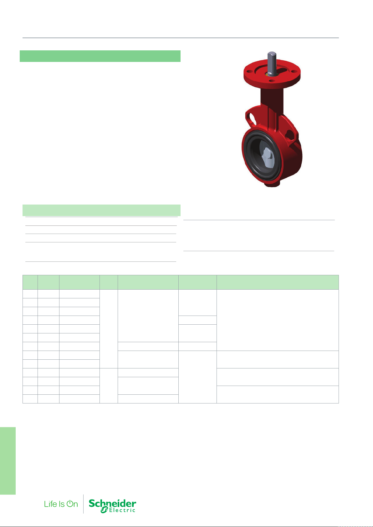
7. Butterfly Valves and Actuators
VF209W-50…500CN
The VF209W is a premium high pressure butterfly valve for heavy
duty HVAC and industrial applications.
The VF209W can be used as a manual isolation valves or be
controlled from a choice of Two-position on/off, 3-point floating and
modulating actuators.
• Wafer type connection for fitting between flanges. PN6
(DN50…DN400), PN10, and PN16 (DN50…DN500)
• The EPDM soft-seat provides a tight closing of the butterfly
valve with the maximum close-off pressure.
• Suitable for cooling with salt, brackish and drinking water
media from the Nylon 11 disc coating.
• Manual adjustment through a ten-position hand lever, gearbox
or the handwheel on the actuators.
Specifications
Pressure Class PN 16
Leakage (EN 12266-1) Gas tight, (Leakage Rate A)
Temperature Range -29 °C…121 °C
Fluids Hot and cold water with
50% Glycol vol. max.
Well water, Saltwater
Valve Type /
DN Kvs
50 124 VF209W-50CN
80 397 VF209W-80CN
100 723 VF209W-100CN 916 0100 000
125 1.083 VF209W-125CN
150 1.591 VF209W-150CN
200 2.852 VF209W-200CN MF200 916 0200 000
250 4.67 VF209W-250CN
300 6.946 VF209W-300CN
350 9.063 VF209W-350CN
400 12.044 VF209W-400CN
450 14.804 VF209W-450CN
500 19.212 VF209W-500CN MF2050
a - The recommended angle of rotation range for modulating control is between 15º and 70º. At a disc angle of 70º, the KV is 55% of the stated Kvs value.
a
Part No.
ΔP Actuator Type Hand Lever Gear Operator
MF68
1200
MF550 / 700 917 0300 000
MF700
1000
MF1450
Main Construction Materials
Body Grey cast iron GG25
Primary & secondary seal, seat EPDM
Disc GGG40 Nylon11 coated
Stem 1.4405-QT
916 0080 00065 243 VF209W-65CN
916 0150 000
917 0400 000
917 0500 000
Actuators
7. Buttery Valves and
70 F-27878-6
Page 71
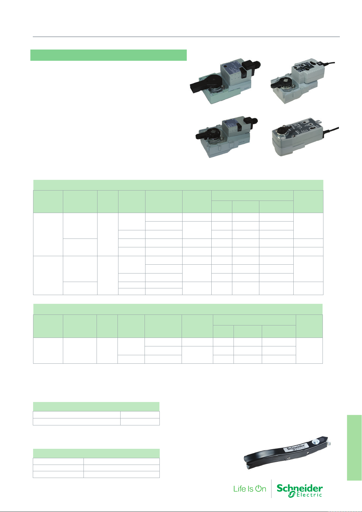
MF20 (SR), MF20-R, MF40 (ER)
The MF20 and MF40 are robust reliable actuators for the
control of the VF208W butterfly valves. These actuators mount to the
VF208W series valves without linkage kits and connect using terminal blocks to simplify and reduce
installation time. The MF20-R actuator allows connection on to
installed TRV-S butterfly valves, no linkage kit is required with this
actuator too.
• Models for Floating / Modulating / On-Off control
• 2…10 V Positional feedback on modulating models
• Latching Manual override
• Direct Handlever / position indicator
• Auxillary switch available as an accessory
• Standard and Spring Return/Electronic return variants
Actuators for VF208W Butterfly Valves
Suitable
VF208W
Valve
DN25…100
DN125-200
Loss of power
function
Stop in place
Spring return
Stop in place
Electronic
return
Torque Control Part Number
MF20-230F 230 Vac 0.4 W 3 W 7 VA
MF40-230F 230 Vac 2.5 W 5 W 9 VA
MF40-24F
20Nm
40Nm
On-Off/3P
2…10 V MF20-24M 0.4 W 2.5 W 5 VA
On-Off MF20SR-TS 24-230 Vac 3 W 7 W 18 VA 75 sec
2…10 V MF20SR-24M 24 Vac/Vdc 3 W 5.5 W 8.5 VA 90 sec
On-Off
/ 3P
2…10 V MF40-24M 2 W 4.5 W 6.5 VA
On-Off MF40ER-24T
2…10 V MF40ER-24M
7. Butterfly Valves and Actuators
MF20 / MF20-R
MF40
Supply
Voltage
24 Vac/Vdc
24 Vac/Vdc
24 Vac/Vdc 3 W 11 W 21 VA 150 sec
Power Consumption
Rest Operation
0.2 W 2.5 W 5.5 VA
2 W 4 W 6 VA
Transformer/
Wire Sizing
MF40ER
MF20SR
Operating
time, 90º
90 secMF20-24F
150 sec
Actuators for installed base of TRV-S butterfly Valves
Suitable
TRV-S
valve size
DN25-125 Stop in place 20Nm
The MF40 and MF40-ER will connect without linkage kit to the TRV-S valves DN150-200
NOTE: Max ∆P Pressure for the valve remains (Max Valve ∆P is a function of construction, not the actuator)
Loss of power
function
Torque Control Part Number
On-Off
/ 3P
2…10 V MF20-24M-R 0.4 W 2.5 W 5V A
MF20-230F-R 230 Vac 0.4 W 3 W 7 VA
Supply
Voltage
24 Vac/Vdc
Power Consumption
Rest Operation
0.2 W 2.5 W 5.5 VA
Transformer/
Wire Sizing
Operating
time, 90º
90 secMF20-24F-R
Accessories
MD-S1, 1 x SPDT auxiliary switch 914 1060 000
MD-S2, 2 x SPDT auxiliary switch 914 1061 000
Handlevers can be ordered to fit the VF208W butterfly valve. This enables the valve to be used
as hand isolation valves:
Hand Levers
DN25…65 915 0065 000
DN80…100 915 0100 000
DN125…200 915 0200 000
F-27878-6 71
Actuators
7. Buttery Valves and
Page 72
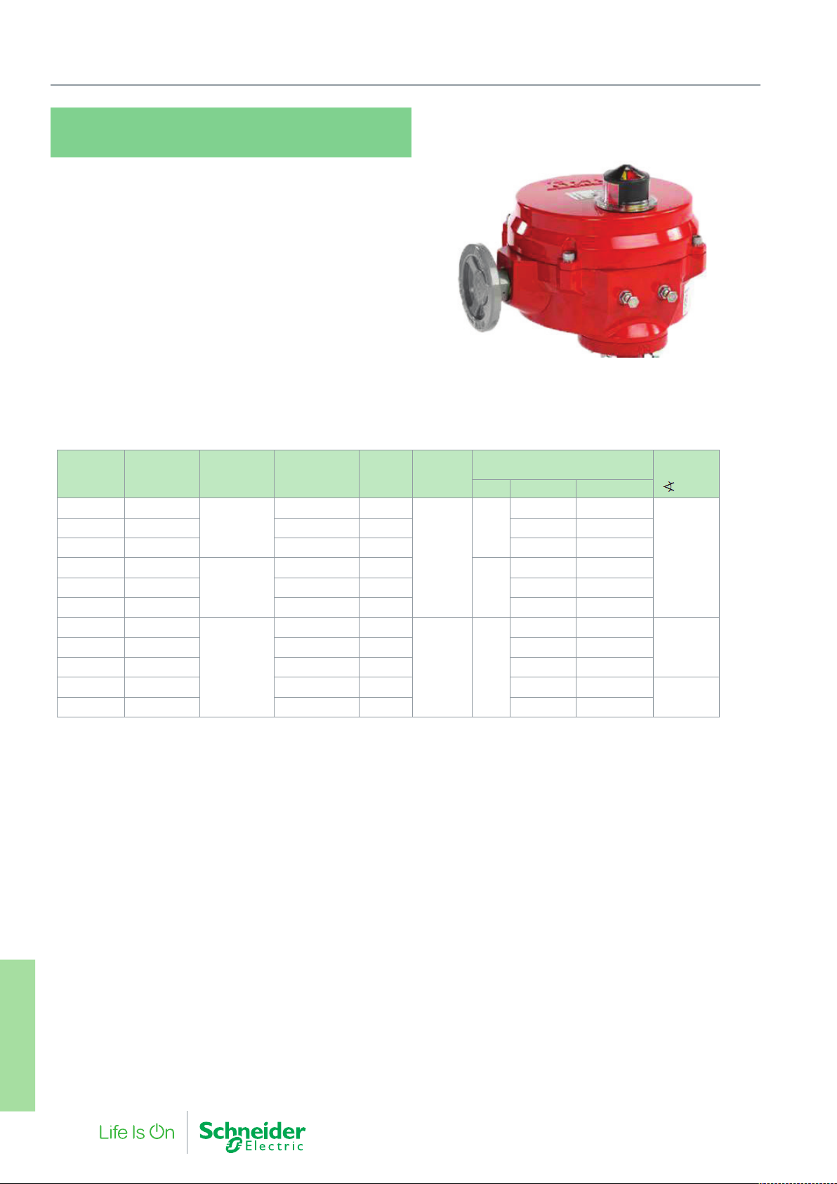
7. Butterfly Valves and Actuators
MF68, MF200, MF550, MF700,
MF1470, MF2050
The direct-coupled IP65 rotary actuators are heavy duty
dedicated actuators for VF209W and VF299W butterfly valves.
• Hand wheel for manual operation as standard
• Adjustable start/end point switch
• 2 additional auxiliary switches as standard
• Terminal connection
• Direct fit without any linkage kits
• Optical position display
• Suitable for outdoor and industrial environments (IP65)
• Very low maintenance
• Self-regulating heater to prevent condensation buildup within the
actuator
• Adjustable positioning speed, 60 sec…360 sec
(modulating models)
• Control signal sensitivity adjustment (modulation models)
Suitable
VF209W
Valve
DN50-150 -
DN200 DN250
DN250-300 DN350-450
DN50-150 -
DN200 DN250
DN250-300 DN350-450
DN50-150 -
DN250-350 DN350-500
DN400-450 -
DN500 -
Suitable
VF299W
Valve
Control Part Number Torque
MF68-24F 68 Nm
Floating & On/
Off
0(2)-10 V
Modulating
Floating & On/
Off
MF200-24F 226 Nm
MF550-24F 565 Nm
MF68-24M 68 Nm
MF200-24M 226 Nm
MF550-24M 565 Nm
MF68-230F 68 Nm
MF200-230F 226 Nm
MF700-230F 735 Nm
MF1450-230F 1470 Nm
MF2050-230F 2034 Nm
Supply
Voltage
24 Vac
230 Vac
Power Consumption
Rest Operation Wire Sizing
43 VA 48 VA
5 W
48 VA 53 VA
69 VA 77 VA
45 VA 50 VA
7 W
50 VA 55 VA
71 VA 79 VA
140 VA 155 VA
108 VA 120 VA
5 W
232 VA 258 VA
275 VA 305 VA
315 VA 350 VA
Operating
Time 90°
60 sec.
36 sec.DN200 DN250
132 sec.
Actuators
7. Buttery Valves and
72 F-27878-6
Page 73

7. Butterfly Valves and Actuators
F-27878-6 73
Actuators
7. Buttery Valves and
Page 74
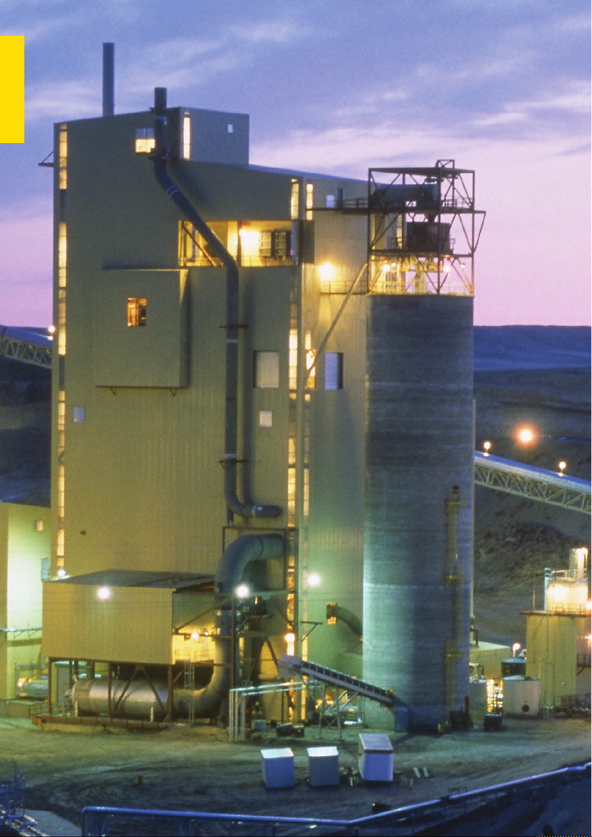
Actuators
8. Shoe Valves and
74 F-27878-6
Page 75
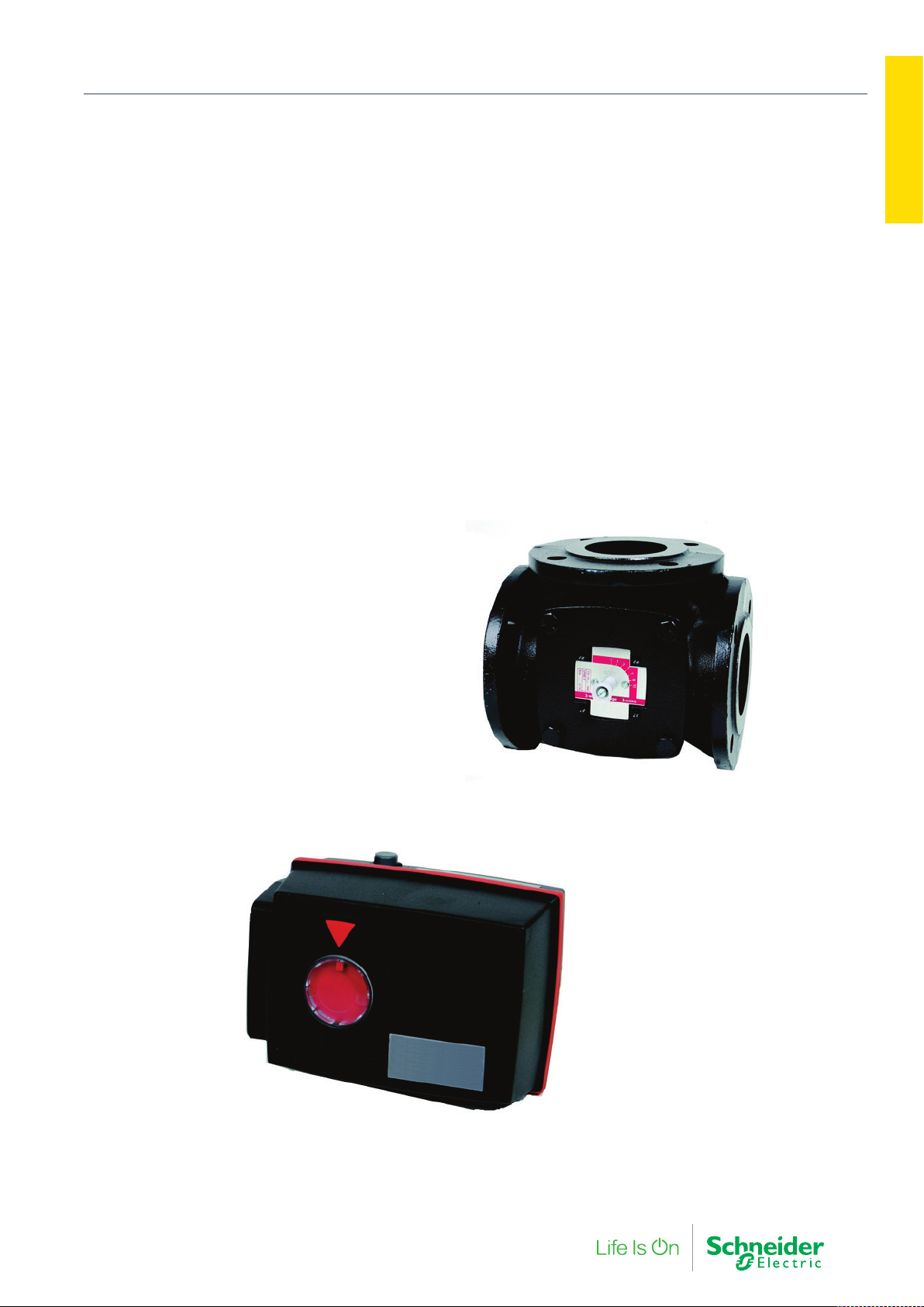
8. Shoe Valves and Actuators
Actuators
Shoe valves are the ideal type of valve for recirculation systems,
allowing control of the fluid flow in both mixing and diverting
circuits. Typical applications include heating, cooling and air
conditioning.
8. Shoe Valves and
F-27878-6 75
Page 76
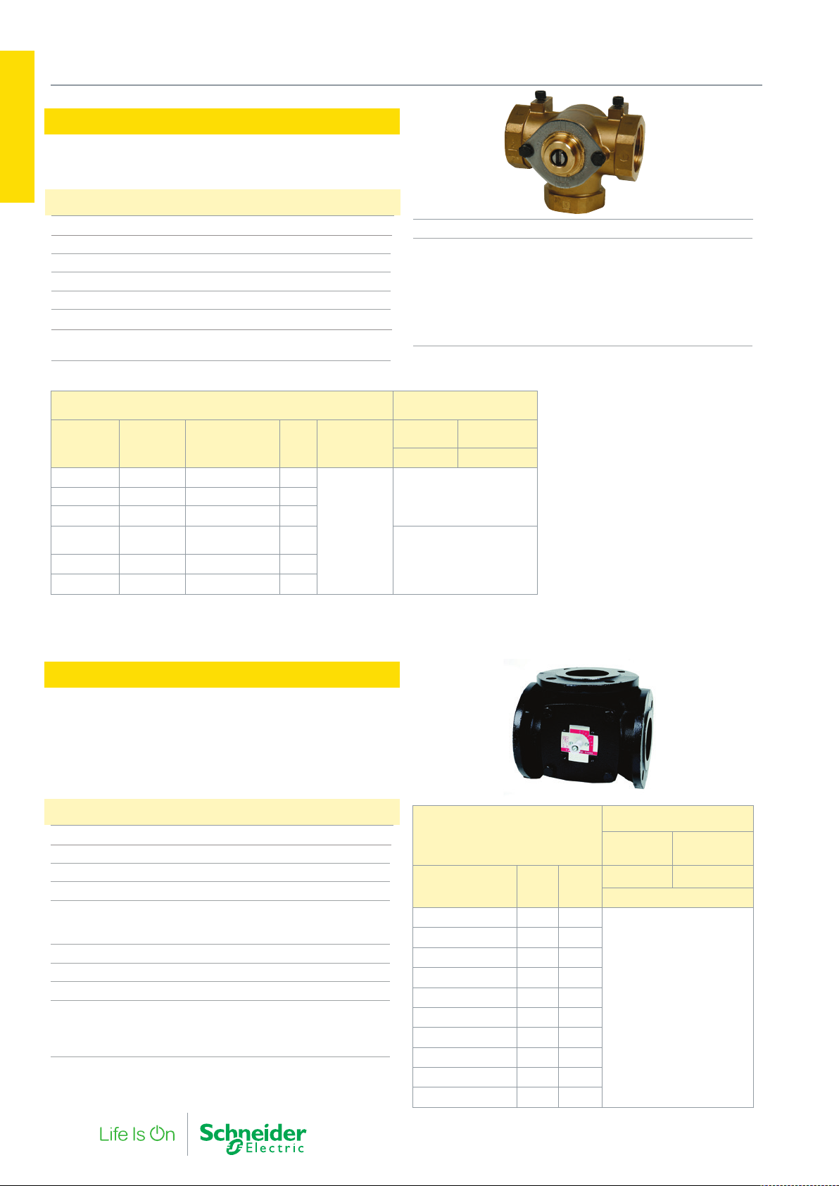
8. Shoe Valves and Actuators
MB
Actuators
The MB is a 3-port screwed rotary shoe valve.
8. Shoe Valves and
Specifications
Design 3-way rotary shoe valve
Pressure Class PN10
Flow Characteristic Port 2 Modified Parabolic
Operating angle 90°
Rangeability (Kvs / Kv
Leakage 0.5% (%of Kvs)
Max. temperature of medium 120 °C
Min. temperature of medium 2 °C
) >50
min.
Connection Screwed Parallel (female) BSP to BS21
Main Construction Materials
Body 12.7…25.4 mm (½”…1”) valves Hot Pressed Brass to BS218
Body 31.75…50.8 mm (1¼”…2” valves) Close Grained Cast Iron
BS1452 Grade 260
Body 65 mm…100 mm Close Grained Cast Iron BS1452
Grade 260 or 220
Spindle High Tensile Brass to BS2874 CZ114
O Rings EPDM
MB
Valve Part
Number
MB1402 12.7 (½”) 0617-9-410 2.0
MB1502 25.4 (1”) 0617-9-410 8.3
MB1552
MB1602 38.1 (1½”) 0617-9-412 21
MB1652 50.8 (2”) 0617-9-413 33
The MD10 is a damper actuator requiring a linkage kit for use with the MB shoe valves. (LMD/MB linkage kit part number 914 1071 000). Order Auxiliary switches separately, type MD-S2
part number 914 1061 000, type MD-S1, part number 914 1060 000.
Size mm
(inches)
31.75
(1¼”)
Reconditioning
Kit Part Number
0617-9-411 12.5
Kvs Rangeability
>50
Max Close-off
Pressure kPa
RM
XRM
2Nm 10Nm
MD10B
MD10A
70MB1452 19.05 (¾”) 0617-9-410 4.0
35
VTRE
The VTRE is a 3-way flanged rotary hydronic shoe valve.
The valve is delivered with a handle for manual operation.
Specifications
Valve type 3-way rotary shoe
Flow characteristic Modified linear
Operating angle 90°
Pressure class PN 6
Water temperature
Max. 110 °C
Min. -10 °C
Max glycol concentration 50%
Max pressure drop 50 kPa
Leakage Max. 1% of Kvs
Main Construction Materials
Body Cast iron
Sleeve Brass
Connections Flanged DIN 2531
VTRE
Part Number
731 7039 000 20 12
731 7041 000 25 18
731 7045 000 32 28
731 7049 000 40 44
731 7053 000 50 60
731 7057 000 65 90
731 7061 000 80 150
731 7065 000 100 225
731 7067 000 125 280
731 7069 000 150 400
DN Kvs
Max Close-off Pressure kPa
Mixing
Application
EM9, M9 EM9, M9B
Diverting
Application
15Nm
50
76 F-27878-6
Page 77
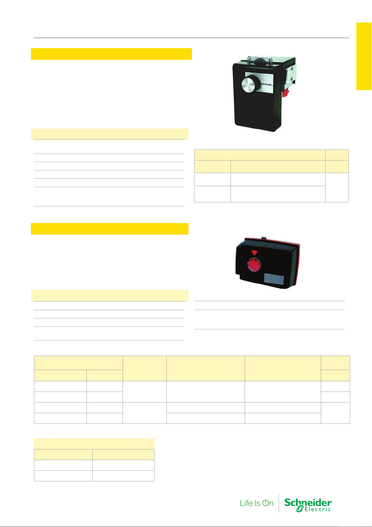
RM, XRM
These actuators operate the MB Shoe Valves. The XRM actuator is
designed to be operated by a three point floating controller providing an output of 24 Vac. The RM actuator is a mains voltage reversing actuator, designed for two-position control when used with a
changeover type thermostat or modulating control when used with
an appropriate controller. On power failure the actuator can be operated manually.
Specifications
Input voltage XRM 24 Vac, 50 Hz, 0.5VA
Input voltage RM 230 Vac, 50 Hz, 5VA
Stroke 90º angular. Reversing
Running time 240 secs
Torque 2Nm
Protection standard IP 41
Environment
Operating Temperature -20 °C…+35 °C with
water at 120 °C
8. Shoe Valves and Actuators
RM, XRM Actuators for MB Valves Torque
Part Number Description Nm
XRM3201 Rotary 24 Vac 3-point
2
RM3601
Rotary 230 Vac
2-point reversing/modulating
Actuators
8. Shoe Valves and
EM9, M9B
The EM9/M9B are electronic actuators for motorising VTRE rotary
shoe valves. EM9 operates on 24 V and is controlled by selectable
0…10 Vdc, 2…10 Vdc, 0…20 mA or 4…20 mA control signal. The
running time can be programmed. EM9/M9B can be operated manually and has a valve position indicator on the front of the unit.
Specifications
Power consumption 3 VA
Duty cycle 10%
Torque 15 Nm
Environment
Operating Temperature -15…+55 °C
M9B, EM9
actuators for valves VTRE
Part Number Description Vac ±10%
860 1010 000 M9B/24
860 1020 000 M9B/230 230
860 1100 000 EM9/90
860 1110 000 EM9/180 180° 120/180/240s
1 - Selectable 0…10 V, 2…10 V, 0…20 mA, 4…20 mA
Control signal Working range Running time
3-point 30-180° 90° 4 min
modulating
1
90° 60/90/120s
Protection class IP 54
Material
Enclosure material Reinforced plastic PA66
Color Black/Red
Power
24
24
M9B, EM9 linkage kits for other valves
Part Number Description
860 0990 000 Linkage E/M9-VTRA
860 0991 000 Linkage E/M9-TRV
2 - NOTE: Not suitable for TRV-S
F-27878-6 77
2
Page 78

9. Damper Actuators
78 F-27878-6
Page 79
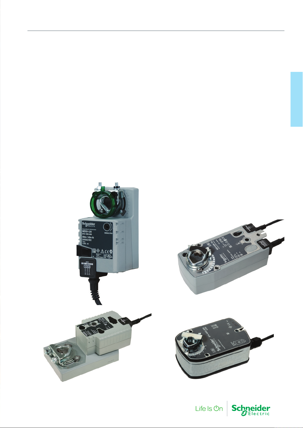
9. Damper Actuators
A wide program of damper actuator products are available from
Schneider Electric, enabling the control of air movement from the
smallest to the very largest air handling equipment.
Intelligent torque control is used in the motors for stall protection
and low power holding providing a dependable range of products
for the facility manager.
9. Damper Acutators
F-27878-6 79
Page 80
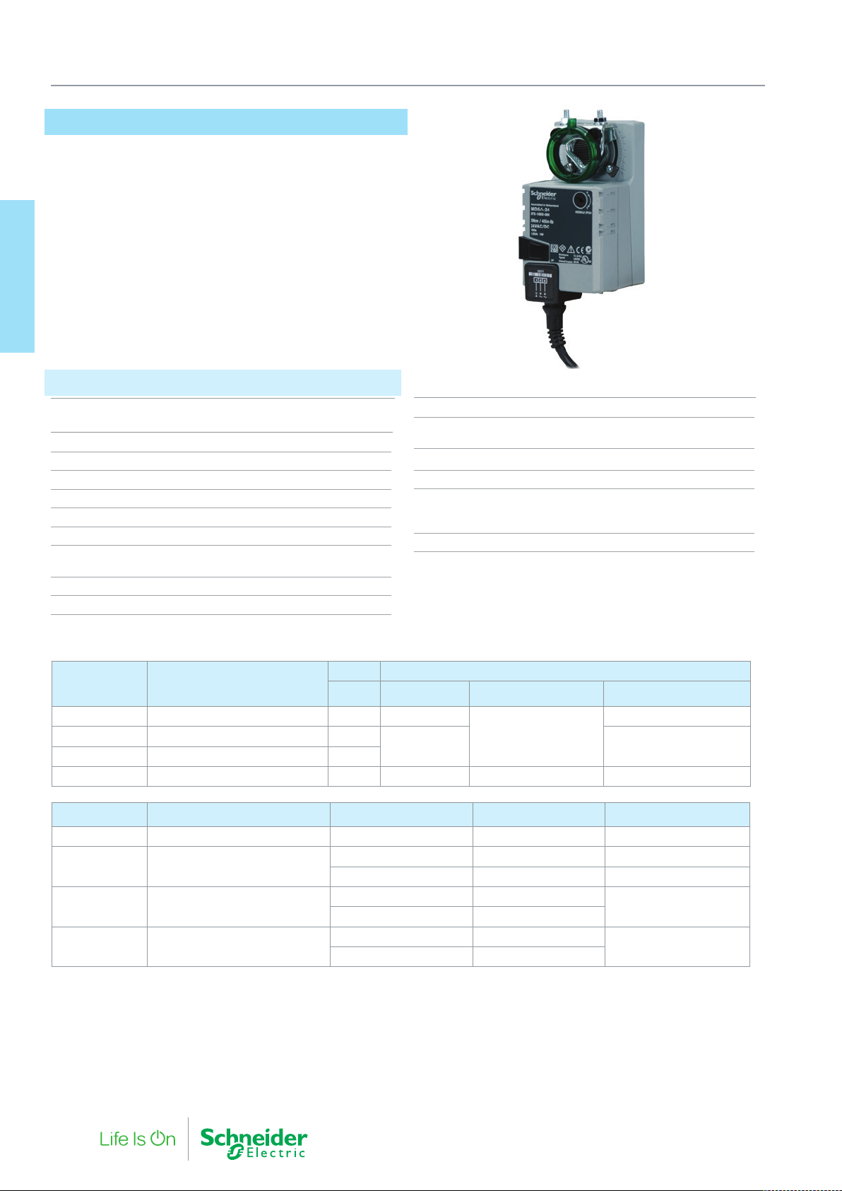
9. Damper Actuators - Non-Spring Return
MD5A, MD10A, MD20A, MD40A
The MD...A are 2…10 V modulating damper actuators
designed for operating air control dampers in ventilation and air
conditioning systems for building services installations.
As an accessory, these modulating actuators have a fully adjustable
auxiliary switch unit.
Damper Actuators can be used with Mounting kits to drive selected
Butterfly and Shoe valves.
9. Damper Actuators
Specifications
Power supply 24 Vac ±20%, 50/60 Hz,
24 Vdc ±20%
Connection cable 1 m, 4×0.75 mm2 (AWG 18)
Input signal range X 0…10 Vdc
Input resistance 100 k Ohm
Operating range 2…10 Vdc (for set angle of rotation)
Synchronisation tolerance ±5%
Position feedback Y 2…10 Vdc (max. 1 mA)
Direction of rotation Reversible with switch 0 / 1
at switch position 0 resp 1
Angle of rotation Max. 95° (adjustable by mechanical stops)
Running time 150 s
Position indication Mechanical
Manual override Gearing latch disengaged with
push-button, self-resetting, manual locking
Enclosure rating IP 54
Humidity 95% RH, non-condensing
Environment
Operating Temperature -30…+50 °C
Storage Temperature -40…+80 °C
Maintenance Maintenance free
Part Number Description
875 1009 000 MD5A-24 5 1 W
875 1019 000 MD10A-24 10
875 1029 000 MD20A-24 20
875 1039 000 MD40A-24 40 4.5 W 2 W 6.5 VA
Torque Power Consumption
Nm In operation At rest For Transformer Sizing
2 VA
2 W 4 VA
0.4 W
Description For air control dampers area Damper spindle Spindle length, mm Spindle diameter, mm
MD5 approx. 1 m² min. 37 6…20
MD10 approx. 2 m²
MD20 approx. 4 m²
MD40 approx. 8 m²
* Optional accessory K-MD10 part number 914 1062 000. For damper actuator accessories see “Damper Actuator Accessories” on page 86.
Clamp on top min. 40 8…26.7
Clamp on bottom* min. 20 8…20
Clamp on top min. 48
Clamp on bottom min. 20
Clamp on top min. 52
Clamp on bottom min. 20
10…20
12…26.7
80 F-27878-6
Page 81
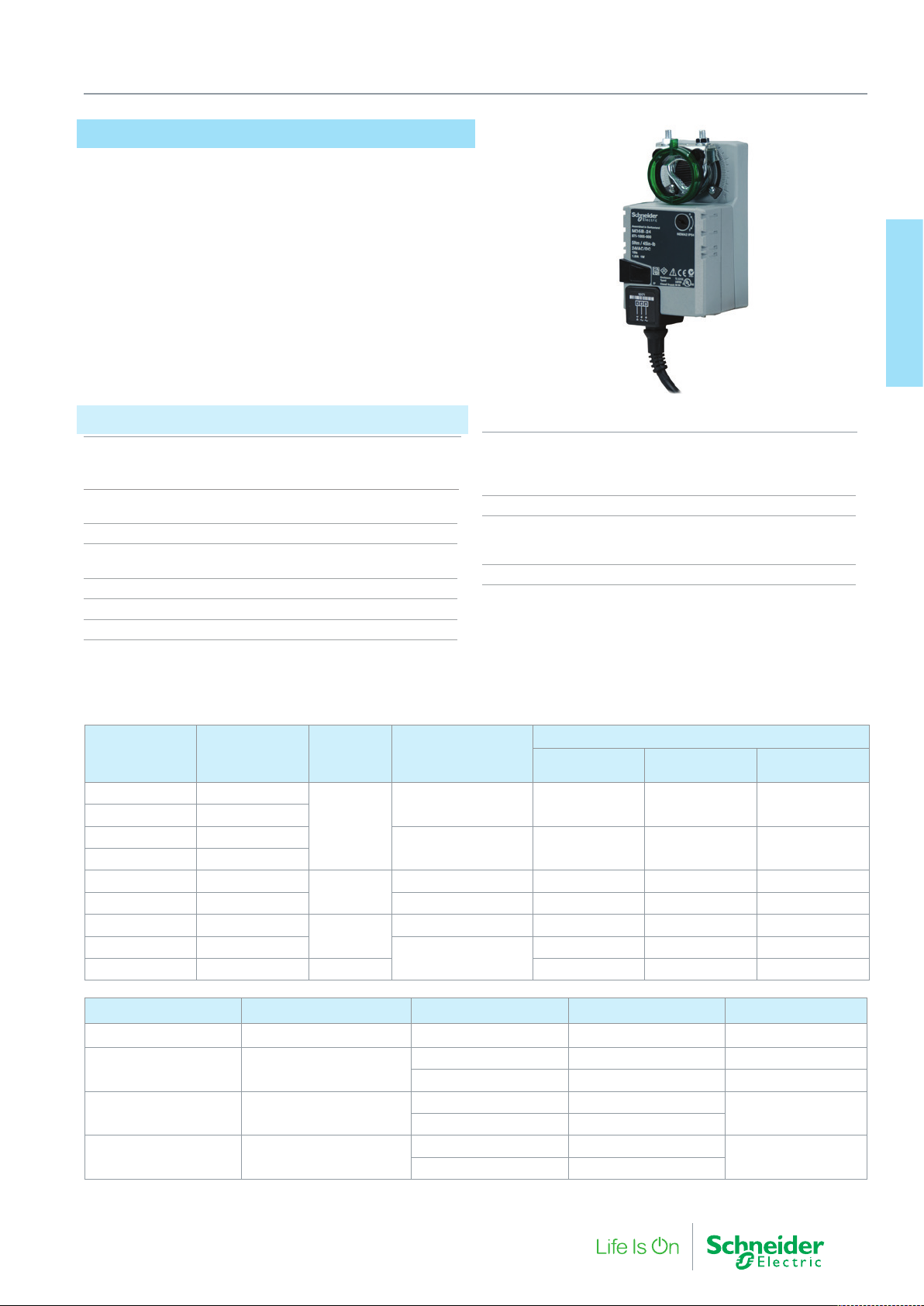
MD5B, MD10B, MD20B, MD40B
The MD...B are on/off damper actuators designed for operating air
control dampers in ventilation and air conditioning systems for building services installations. The actuators are available in 24 Vac/Vdc
or 230 Vac versions and versions with an integrated end point switch
(-S types). The Auxiliary switch is also available as an accessory.
Damper Actuators can be used with Mounting kits to drive selected
Butterfly and Shoe valves.
Specifications
Connection cable
Actuator 1 m, 3×0.75 mm2 (AWG 18)
Auxiliary switches (-S) 1 m, 3×0.75 mm2 (AWG 18)
Angle of rotation max. 95° (adjustable by
mechanical stops)
Running time 150 s
Direction of rotation Reversible with switch 0 / 1
at switch position 0 resp 1
Position indication Mechanical
Auxiliary switch 1 mA…3 (0.5) A, 250 Vac
Switching point (adjustable 0…100% )
9. Damper Actuators - Non-Spring Return
9. Damper Acutators
Protection Class
MD..B-24(-S) III Safety extra-low voltage
MD..B-230(-S) II Totally insulated
Enclosure rating IP 54
Humidity 95% RH, non-condensing
Environment
Operating Temperature -30…+50 °C
Storage Temperature -40…+80 °C
Maintenance Maintenance free
Part Number Description
875 1001 000 MD5B-230
875 1003 000 MD5B-230-S
875 1005 000 MD5B-24
875 1007 000 MD5B-24-S
875 1011 000 MD10B-230
875 1015 000 MD10B-24 24 Vac/Vdc ± 20% 1.5 W 0.2 W 3.5 VA
875 1021 000 MD20B-230
875 1025 000 MD20B-24
875 1035 000 MD40B-24 40 4 W 2 W 6 VA
Description For air control dampers area Damper spindle Spindle length mm Spindle diameter mm
MD5 approx. 1 m² min. 37
MD10 approx. 2 m²
MD20 approx. 4 m²
MD40 approx. 8 m²
* Optional accessory K-MD10 part number 914 1062 000.
For damper actuator accessories see “Damper Actuator Accessories” on page 86.
Torque
Nm
5
10
20
Power supply
230 Vac -60%/+15% 1.5 W 0.4 W 3.5 VA
24 Vac/Vdc ± 20% 1 W 0.2 W 1.5 VA
230 Vac -60%/+15% 2.5 W 0.6 W 5.5 VA
230 Vac -60%/+15% 2.5 W 0.6 W 6 VA
24 Vac/Vdc ± 20%
Clamp on top min. 40 8…26.7
Clamp on bottom* min. 20 8…20
Clamp on top min. 42
Clamp on bottom min. 20
Clamp on top min. 42
Clamp on bottom min. 20
Power Consumption
In operation At rest
2 W 0.2 W 4 VA
For Transformer
Sizing
6…20
10…20
14…26
F-27878-6 81
Page 82
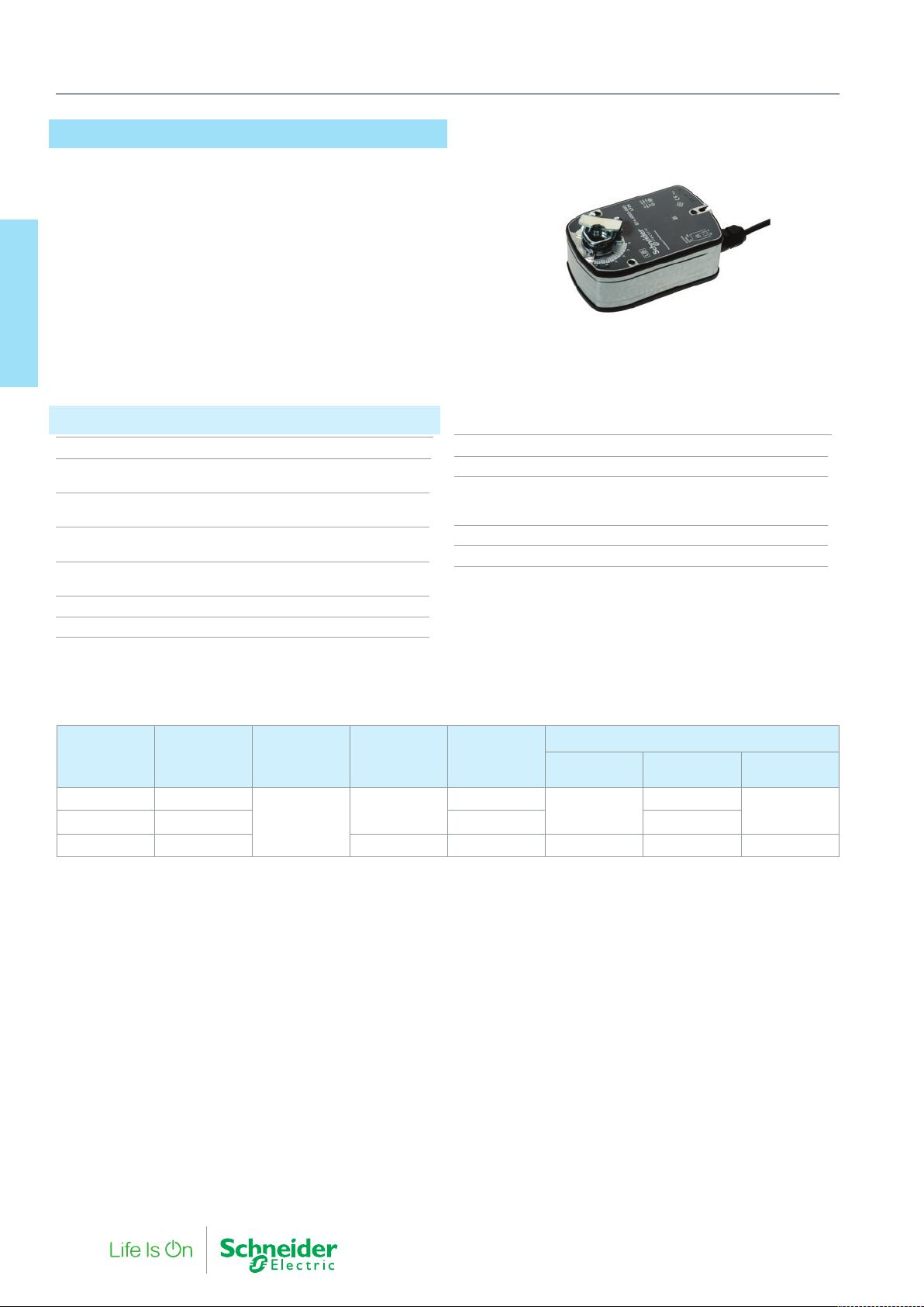
9. Damper Actuators - (Spring / SuperCap Return)
LF24, LF230, LF24-SR
The LF series are compact, low-torque, spring return damper actuators suitable for controlling air dampers up to 0.8m² cross sectional
area.
The LF24 and LF230 versions are on/off controlled. The LF24-SR
version is for 0…10 V modulating control with 2…10 V position
feedback
9. Damper Actuators
Specifications
Connection cable 2×0.75 mm2 (AWG 18)
Angle of rotation Max. 95° (adjustable 37…100% with
additional limit stop ZDB-LF)
Torque
Spring return Min. 4 Nm (3 ft-lbf)
Running time
Actuator 40…75 s (0…4 Nm (0…3 ft-lbf))
Spring return Approx. 20 s (at -20…+50 °C)
max. 60 s (at -30 °C)
Direction of rotation Selected by mounting L/R
Position indication Mechanical
Enclosure rating IP 54
Humidity 95% RH, non-condensing
Environment
Operating Temperature -30…+50 °C
Storage Temperature -40…+80 °C
Service life min. 60,000 operations
Maintenance Maintenance free
Part Number Description
874 0003 000 LF24
875 0003 000 LF230 230 Vac±14% 3 W
877 0003 000 LF24-SR 0…10 V 24 Vac±20% 2.5 W 1 W 5 VA
For damper actuator accessories see “Damper Actuator Accessories” on page 86.
Torque
Nm
4
Control
Signal
on/off
Power supply
24 Vac±20%
Power Consumption
In operation At rest
5 W
2.5 W
For Transformer
Sizing
7 VA
82 F-27878-6
Page 83
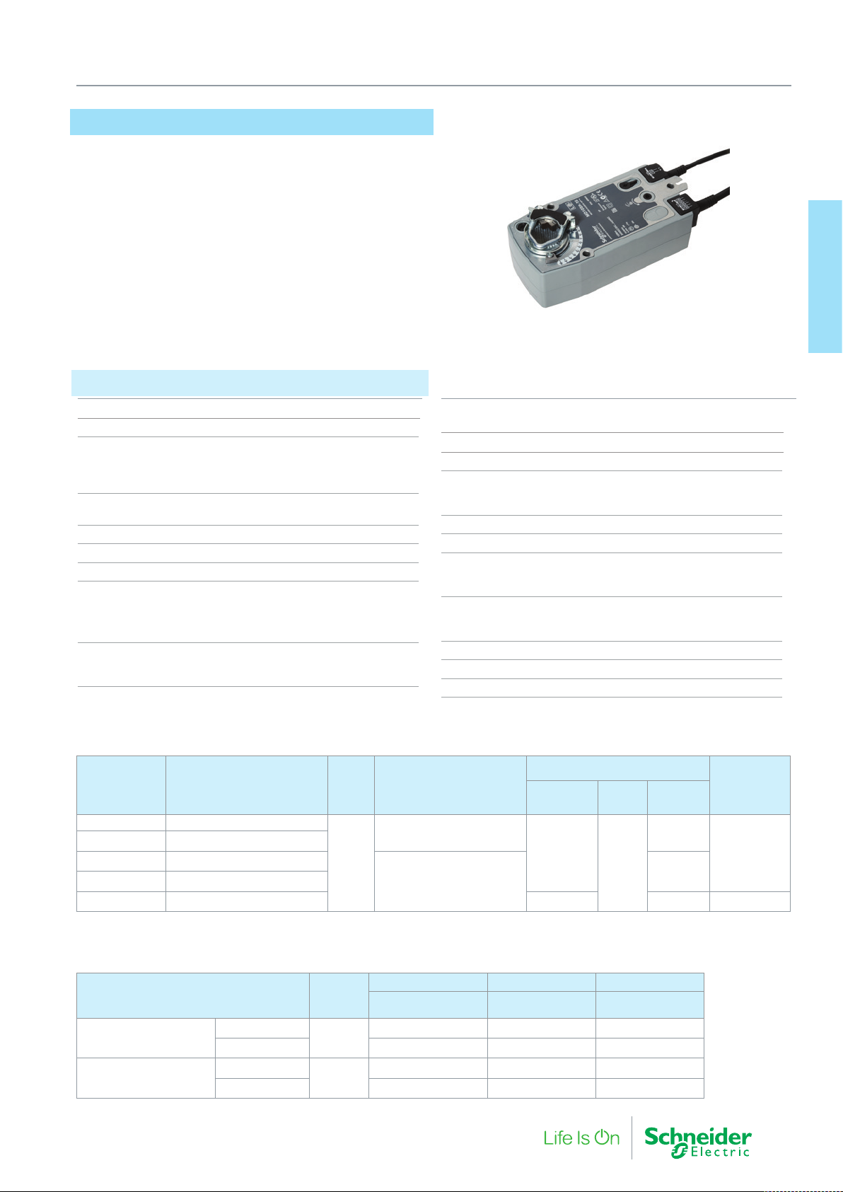
9. Damper Actuators - (Spring / SuperCap Return)
MD10 SR
The MD10 SR is a compact spring return damper actuator for the
operation of ventilation dampers up to 2m2 in building service instal-
lations
Specifications
Motor Torque Min. 10 Nm@ Nominal Voltage
Spring Return Min. 10Nm
Running Time, Motor
Modulating ≤150 s
On/off ≤75 s
Spring Return ≤20 s
Control Signal, modulating
Range of Operation (X) 2…10 Vdc
Input Resistance 100 kΩ
Position Feedback (Y) 2…10 Vdc, max. 0.5mA
Position accuracy +/- 5%
Cable Size 1m
-24M, 4 x 0.75 mm2
-T, -24T 2 x 0.75 mm2
S2 versions 2+6 x 0.75 mm
Direction of Rotation
Motor Reversible with Switch I/O
Spring return via mounting orientation, L / R
Manual Override 5 mm Hex key, supplied
plus interlocking switch
Adjustable angle of rotation 0…Max 95°
Position indication Mechanical
Protection Class
24 V versions III Extra low Voltage
230 V Versions II Totally insulated
Enclosure rating IP54
Humidity 95% r.h. Non-condensing
Environment
Operating Temperature -30 °C…+ 50 °C
Storage Temperature -40 °C…+ 80 °C
Sound power level
Motor ≤40 dB (mod.) 45dB (on/off)
2
Spring return ≤62 dB
Service Life Min.60,000 emergency positions
Maintenance Maintenance free
Weight 2.1Kg
9. Damper Acutators
Part Number
MD10SR-T MD10 SR-24/230T 1M54 00
MD10SR-TS MD10 SR-24/230FTS 1M54 00
MD10SR-24T MD10 SR-24T 1M54 00
MD10SR-24TS MD10 SR-24TS 1M54 00
MD10SR-24M MD10 SR-24M 1M54 00
For damper actuator accessories see “Damper Actuator Accessories” on page 86.
Type Designation
Torque
Nm
10
Power Supply
24…240 Vac / 24…125 Vdc
24 Vac/Vdc
Power Consumption
In
Operation
6W
3.5W 5.5VA 2…10 V Mod.
At Rest
2.5W
For wire
sizing
9.5VA
8.5VA
Control Signal
On/Off
Spindle Clamp
Damper Spindle Attachment
Clamp on Top With Insert
Without Insert
Clamp on Bottom With Insert
Without Insert
Spindle
Length
≥85 mm
≥15 mm
F-27878-6 83
Spindle Diameter Spindle Diameter Spindle Diameter
l
10…22 mm 10 mm 14…25.4 mm
19…25.4 mm 12…18 mm
10…22 mm 10 mm 14…25.4 mm
12…18 mm 19…25.4 mm
Page 84
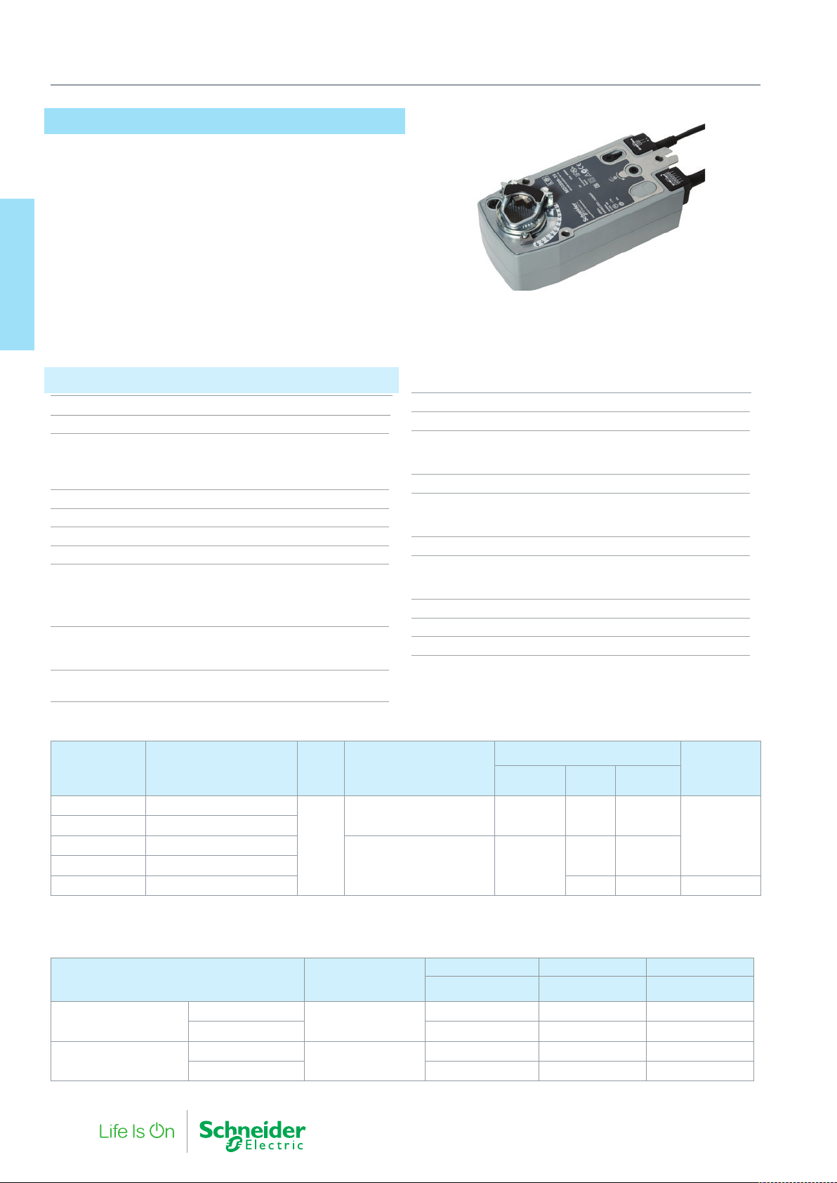
9. Damper Actuators - (Spring / SuperCap Return)
MD20 SR
The MD20 SR is a compact spring return damper actuator for the
operation of ventilation dampers up to 4m2 in building service instal-
lations
9. Damper Actuators
Specifications
Motor Torque Min. 20 Nm@ Nominal Voltage
Spring Return Min. 20Nm
Running Time, Motor
Modulating ≤150 s
On/off ≤75 s
Spring Return ≤20 s
Control Signal, modulating 2…10 Vdc
Input Resistance 100 kΩ
Position Feedback (Y) 2…10 Vdc, max. 0.5mA
Position accuracy +/- 5%
Cable Size 1m, 0.75 mm2
-24M, 4 x 0.75 mm2
-T,-24T 2 x 0.75v mm2
S2 versions 2+6 x 0.75 mm
Direction of Rotation
Motor Reversible with Switch I/O
Spring return via mounting orientation, L / R
Manual Override 5 mm Hex key, supplied
plus interlocking switch
Adjustable angle of rotation 0…Max 95°
Position indication Mechanical
Protection Class
24 V versions III Extra low Voltage
230 V Versions II Totally insulated
Enclosure rating IP54
Environment
Operating Temperature -30 °C…+ 50 °C
Storage -40 °C…+ 80 °C
Humidity 95% r.h. Non-condensing
Sound power level
Motor ≤40 dB (mod.) ≤45dB (on/off)
Spring return ≤62 dB
Service Life Min.60,000 emergency positions
2
Maintenance Maintenance free
Weight approx. 2.1Kg
Part Number
MD20SR-T MD20 SR-24/240T 1M54 00
MD20SR-TS MD20 SR-24/240TS 1M54 00
MD20SR-24T MD20 SR-24T 1M54 00
MD20SR-24TS MD20 SR-24TS 1M54 00
MD20SR-24M MD20 SR-24M 1M54 00 3W 7VA 2…10 V Mod.
For damper actuator accessories see “Damper Actuator Accessories” on page 86.
Type Designation
Torque
Nm
20
Power Supply
24…240 Vac / 24…125 Vdc 6.5W 3.3W 18VA
24 Vac/Vdc 5W
Power Consumption
In
Operation
At Rest
2.5W 7.5VA
For wire
sizing
Control Signal
On/Off
Spindle Clamp
Damper Spindle Attachment Spindle Length
Spindle Diameter Spindle Diameter Spindle Diameter
l
Clamp on Top
Clamp on Bottom
With Insert
Without Insert 19…25.4 mm 12…18 mm
With Insert
Without Insert 19…25.4 mm 12…18 mm
≥85 mm
≥15 mm
84 F-27878-6
10…22 mm 10 mm 14…25.4 mm
10…22 mm 10 mm 14…25.4 mm
Page 85
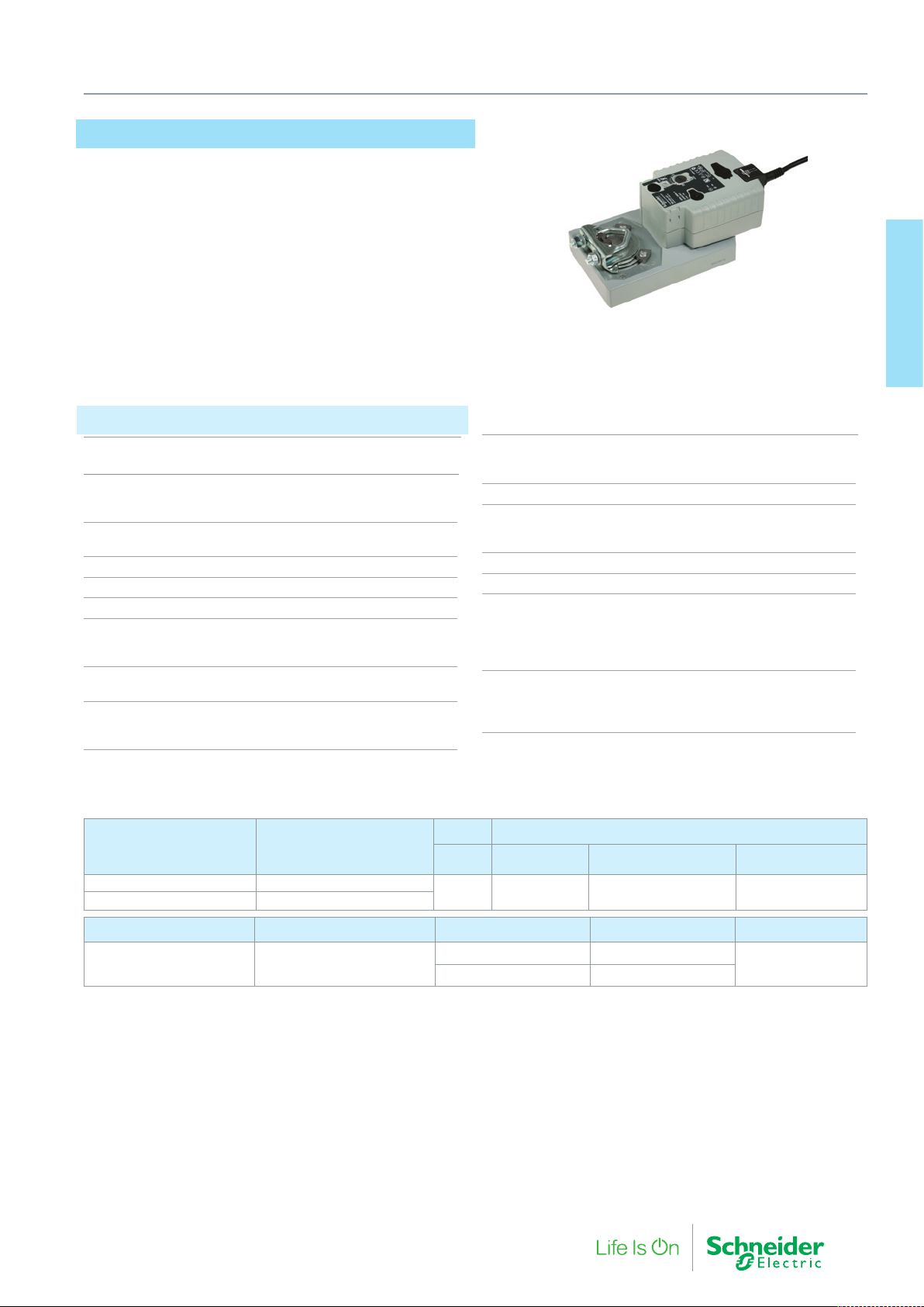
9. Damper Actuators - (Spring / SuperCap Return)
MD40 ER
The MD40 Electronic Return (SuperCap) Damper Actuator is a
powerful rotary damper actuator with super capacitor technology for
positional electronic drive return in the event of a power failure.
• Air Dampers up to 8m2
• 24 Vac/Vdc
• 2…10 V Position Feedback
• Long Life Supercaps
Specifications
Power Supply AC: 19.2…28.8V; 50/60 Hz
DC: 21.6…28.8V
Running Time
Motor Driven 150 s/90°
Capacitor Driven 35 s/90°
Control Signal
Range of Operation (X) 2…10 Vdc
Input Resistance 100 kΩ
Position Feedback (Y) 2…10 Vdc, max. 0.5 mA
Position accuracy +/- 5%
Functional Data
Electronic Return position 0…100% of max. angle
or rotation (POP dial)
Direction of Rotation
Motor (mod.) Reversible with Switch 0/1
Electronic Return (SuperCap) Position 0…100%
(any position between,
as set by POP dial)
9. Damper Acutators
Angle of Rotation Max. 95°,
limited both ends,
adjustable end stops
Position Indication Mechanical
Environment
Operating Temperature -30 °C…+ 50 °C
Storage Temperature -40 °C…+ 80 °C
Humidity 95% r.h. Non-condensing
Weight approx. 1.8 kg
Safety
Protection Class III Safety Extra Low Voltage /
UL Class 2 Supply
Enclosure rating IP54
NEMA2, UL Enclosure Type 2
Standards CE to 2004/108/EC
cULus to UL60730-1A
UL60730-2-14 and CAN/CSA E60730-1:02
IEC/EN 60730-1 and IEC/EN 60730-2-14
Part Number Control
MD40ER-24M Modulating
MD40ER-24T Two-Position
Description For air control dampers area Damper spindle Spindle length, mm Spindle diameter, mm
MD40 approx. 8 m²
For damper actuator accessories see “Damper Actuator Accessories” on page 86.
F-27878-6 85
Torque Power Consumption
Nm In operation At rest For Transformer Sizing
Min. 40
Nm
Clamp on top min. 52
Clamp on bottom min. 20
11 W @ nominal
torque
<3 W ≤21 VA
12…26.7
Page 86

9. Damper Actuators
Damper Actuator Accessories
Mechanical Accessories
Name Description Part Number
AV8-25 Shaft extension
K-MD10 Reversible spindle clamp 914 1062 000
KH8 Universal damper crank arm
9. Damper Actuators
ZG-MDSR Mounting Kit for flat and side instal-
ZDB-LF Angle of rotation limiter and pointer 914 1045 000
ZG-MD20 Parallel lever linkage kit 914 1063 000
Z-AF Mounting plate adaptor for anti-rotation
Length approx. 250 mm
For damper spindles
8…25 mm dia. or 10…25 mm square
Zinc-plated steel
For damper spindles
10…18 mm dia. or 10…14 mm square
Slot width 8.2 mm
lation
strap-- Retrofitting MD20 SR or MD10
SR from AF installation
Electrical Accessories
Name Description Part Number
MD-S1
MD-S2
Auxiliary switch, add-on
1xSPDT 1mA…3(0.5)A, 250 Vac
Auxiliary switch, add-on
2xSPDT 1mA…3(0.5)A, 250 Vac
914 1023 010
914 1021 000
914 1046 000
914 1047 000
914 1060 000
914 1061 000
Actuators
MD5 MD10 MD20 MD40 LF MD10 SR MD20 SR MD40 ER
x x
x
x x
x
x
x
x
Actuators
MD5 MD10 MD20 MD40 LF
x
MD10 SR /
MD20 SR
Actuators only available
with integrated switches
MD40 ER
x
86 F-27878-6
Page 87

Notes
9. Damper Actuators
9. Damper Acutators
F-27878-6 87
Page 88

Speciali Products
10. Legacy and Other
88 F-27878-6
Page 89
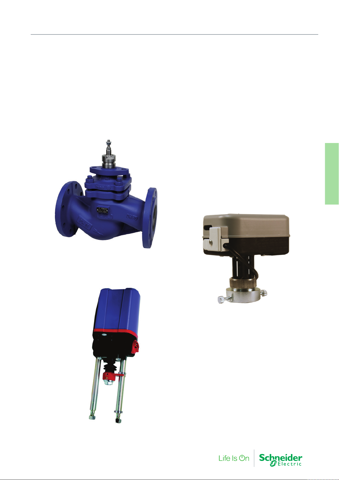
10. Specialist Products
Specialist products provide solutions for our wide installation base
or the more demanding hydronic applications, such as globe and
zone valves capable of handling higher pressure drops typically
experienced in high rise buildings.
Speciali Products
10. Legacy and Other
F-27878-6 89
Page 90
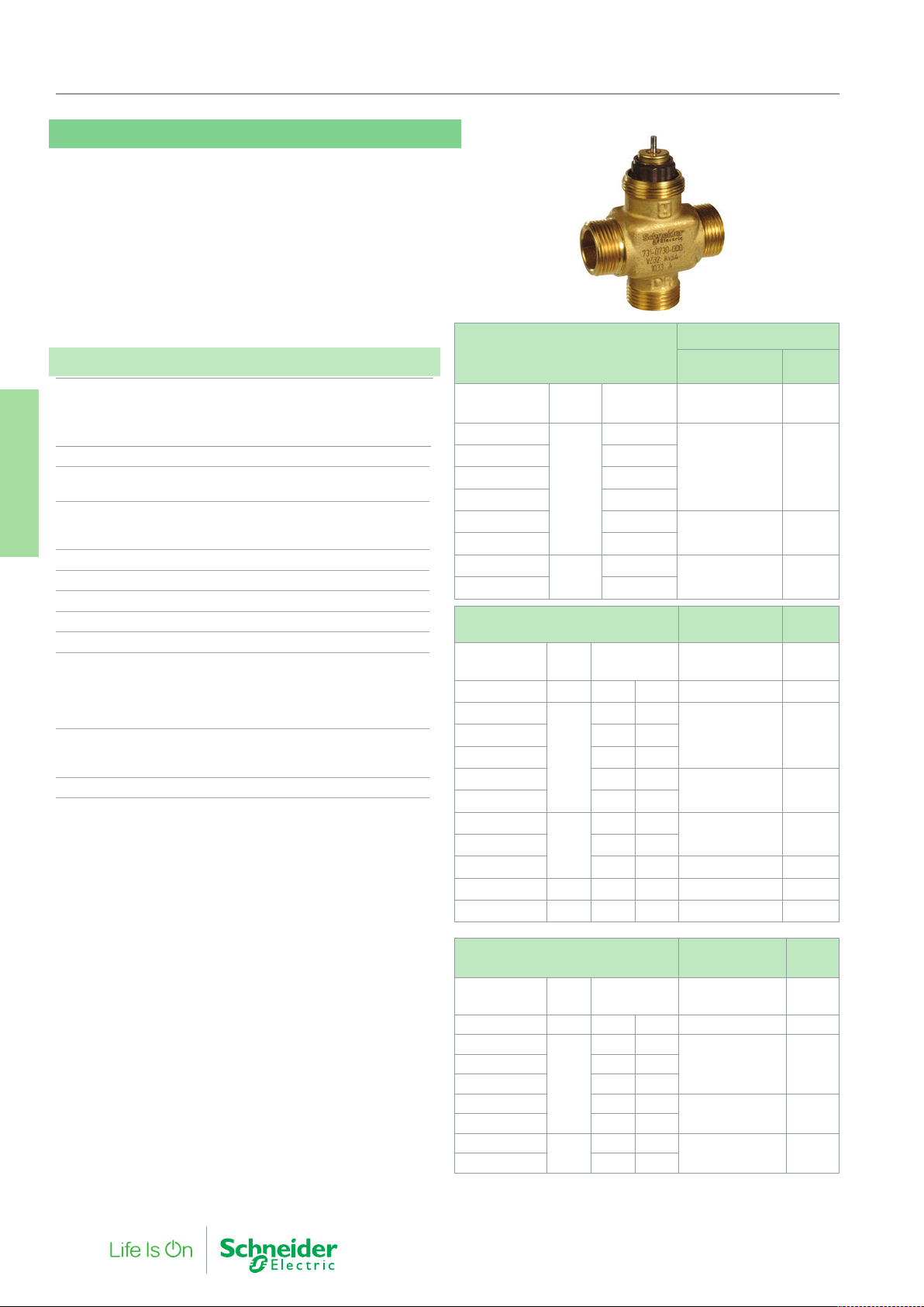
10. Specialist Products
VZ22, VZ32, VZ42
These long stroke (6.5 mm) zone valves have a very high working
pressure capability and can be driven from a wide range of actuators including types with LON communication. The VZ22, VZ32 and
VZ42 valves are a robust range of zone valves in 2-way, 3-way and
3-way with 4 ports.
With this range of products, the same valve body can be driven buy
both a thermal and motoric actuator.
Specifications
Valve types
2-way valve VZ22
3-way valve VZ32
3-way with bypass VZ42
Nominal pressure rating PN16 (232 psi)
Flow characteristics Equal percentage port A-AB
Linear for bypass B-AB
Rangeability
2-way valve 50:1
Speciali Products
10. Legacy and Other
3-way valve 50:1 for controlled port
Leakage rate < 0.02% of kv
Connections Exter nal thread
Suitable medium Water according to VDI 2035
Max. glycol concentration 50%
Controlled water temperature 2…120 °C (36…248°F)
Material
Valve body DN15 yellow brass
DN20 red brass
Stem Stainless steel
Plug Brass
Function
2-way valve Stem up to open port A to B
3-way valve Stem up to close port A to AB
Stroke 6.5 mm (0.26 in.)
(1) Up to 1000 kPa system pressure
For fittings please see the tables
page 21 and “Connections for VZ*19 Series Zone Valves” on page 23.
“Connections for VZ*08 Series Zone Valves”
on
Max Close-off Pressure kPa
VZ22
Part Number
721 0702 000
Size
(mm)
Kv 180N 95N
0.16
721 0706 000 0.25
721 0710 000 0.4
721 0714 000 0.63
15
721 0718 000 1
721 0722 000 1.6
721 0726 000
721 0730 000 4
VZ32
Part Number
A-AB B-AB
731 0706 000
731 0710 000 0.4 0.25
731 0714 000 0.63 0.4
731 0718 000 1.0 0.63
731 0722 000 1.6 1.0
731 0726 000
731 0730 000 4.0 2.5
731 0727 000 2.5 1.6 100 50 (1)
731 0730 000
731 0731 000 20 4.0 2.5 100 50 (1)
20
Size
(mm)
15
20
2.5
Kv 180N 95N
0.25 0.16
2.5 1.6
MZ18L / MZ18A
/ MZ18B
MZ10T /
MZ95
1600 600
1200 180
400 50 (1)
MZ18L / MZ18A
/ MZ18B
800 600
250 180
240 -
MZ10T /
MZ95
VZ42
Part Number
A-AB B-AB
741 0706 000
741 0714 000 0.63 0.4
741 0718 000 1.0 0.63
741 0722 000 1.6 1.0
741 0726 000
741 0730 000 4.0 2.5
Size
(mm)
15
20
Kv 180N 95N
0.25 0.16
2.5 1.6
MZ18L / MZ18A /
MZ18B
800 500741 0710 000 0.4 0.25
250 150
240 -
MZ10T /
MZ95
90 F-27878-6
Page 91
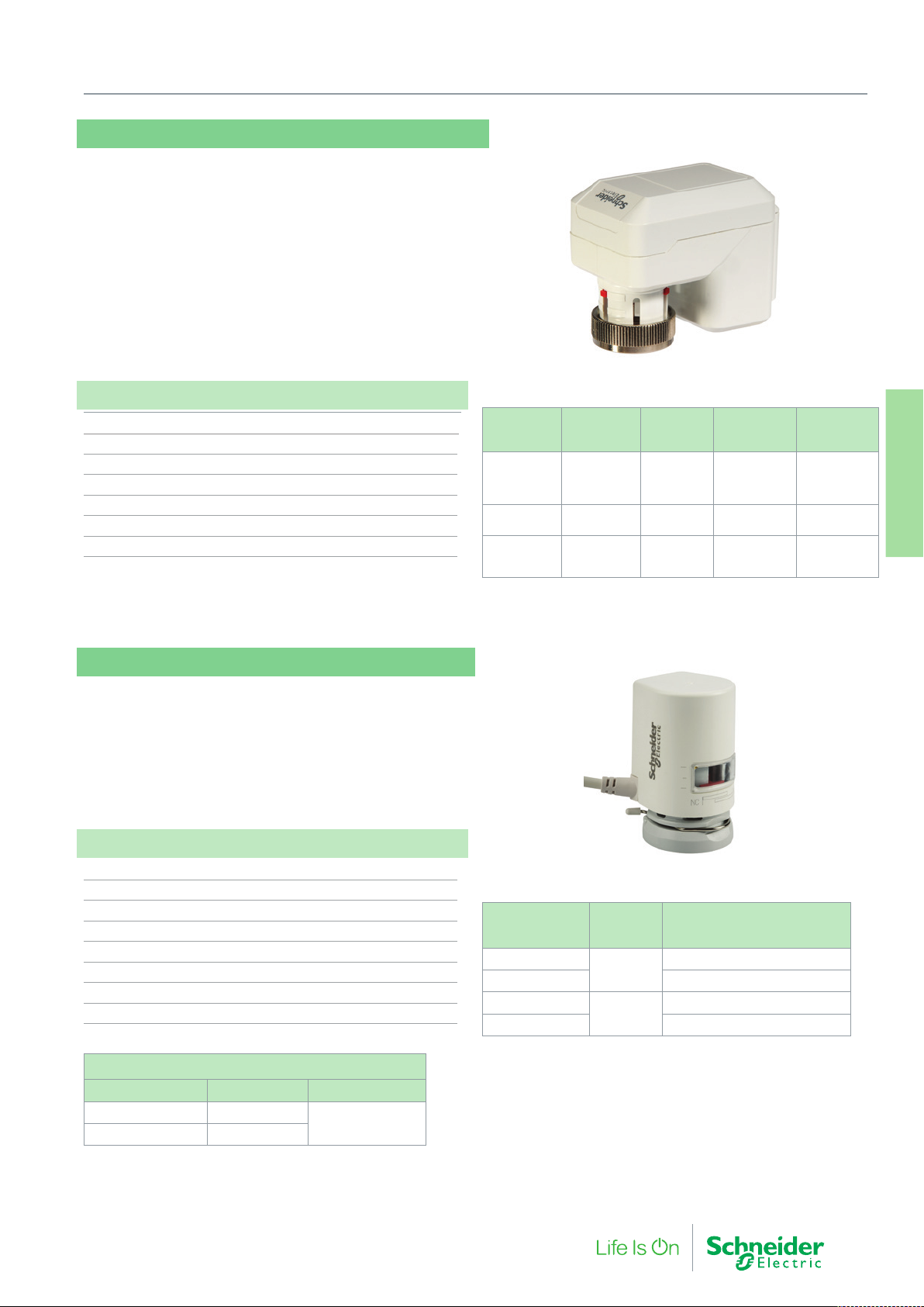
MZ18A, MZ18B, MZ18L
For VZ22, VZ32, VZ42 Zone Valves, the MZ18 is a compact electromechanical zone valve actuator designed for use with the VZ*2
valves.
These actuators feature reliable long term operation ensured from
a simple design without the need for end switches. Visual position
indication on all models.
Specifications
Supply voltage 24 Vac
Running time (full stroke, 50 Hz) 150 s
Stroke 6.5 mm
Force 180 N
Connection cable 1.5 m
Coupling ring M 30 x 1.5
Enclosure rating IP 42
Part
number
845 5100 000 MZ18A-24
845 5101 000 MZ18B
845 5102 000
Description Control
MZ18L
(LON)
10. Specialist Products
0…10 V,
2…10 V,
Direct/
Reverse
3 Point
Floating
SNVT_lev_
percent
0…100%
Power
Consumption
1.4 VA 0…55 °C
0.7 VA 0…60 °C
1.4 VA 0…55 °C
Ambient
Temperature
Speciali Products
10. Legacy and Other
MZ95
The MZ95 is a thermal zone valve actuator designed for use with the
VZ*2 valves.
Normally used for on/off two-position control but PWM is possible
with the appropirate controller.
A discreet design with high IP rating in any orientation, clear position
indication and alternative cable lengths.
Specifications
Supply voltage 24 Vac
Power Consumption 2 W
Stroke 8 mm
Force 95 N
Connection Cable (standard) 2.5 m
Coupling Ring M30 x 1.5
Ambient Operating Temperature 0…55 °C
Enclosure rating IP44
Additional cable set, MZ95
Part Number Cable length Qty in pack
911 4205 000 5.0 m
911 4210 000 10.0 m
10 pcs
Part Number Voltage
MZ95NC-24T
MZ95NO-24T Stem UP (Normally Open)
MZ95NC-230T
MZ95NO-230T Stem UP (Normally Open)
24 Vac/Vdc
230 Vac
Actuator Stem Action
( 2-way Valve Function)
Stem Down (Normally Closed)
Stem Down (Normally Closed)
F-27878-6 91
Page 92
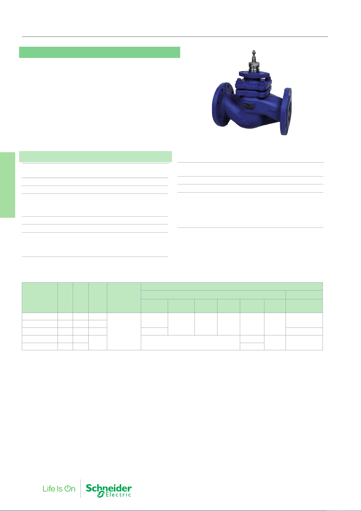
10. Specialist Products
V222
The V222 is a large flanged balanced globe valve, suitable for
control of large flows in heating and air conditioning systems. The
balanced plug enables a low actuating force to control the valve. A
stainless steel seat allows a large pressure drop across the valve.
Suitable for a wide range of applications using hot water or deaerated cooling water
Specifications
Design 2-way pressure balanced plug valve,
stem down, closed
Pressure class PN 16
Flow characteristics Equal Percentage
Stroke
DN65…DN100 30 mm
Speciali Products
10. Legacy and Other
DN125…DN150 50 mm
Rangeability (Kvs/Kv
Leakage <0.05% of Kvs
Stem
DN 65…100 M8
DN 125…150 M16
(fitted with Hex Bush for M22/M50 actuators)
) >50
min.
Max. temperature of medium 150 °C
Min. temperature of medium -10 °C
Connection Flange according ISO 7005-2
Max. glycol/concentration 50%
Main Construction Materials
Body Grey Cast Iron GG25
Stem Stainless steel SS 1.4021
Plug Stainless steel SS 1.4021
Seat Stainless steel SS 1.4021
Packing box Spring-loaded PTFE-V-ring
Max Close-off Pressure (kPa)
Part Number
721 2254 000 65 63 800
721 2258 000 80 85 400
721 2262 000 100 130 150 1100 800
721 2266 000 125 250
721 2270 000 150 350 1400
Replacement packing box:
DN65…DN100: 1 001 0820 0
DN125…DN150: 1 001 0821 0
Stem Heater
DN65…DN100: 880 0112 000
DN125…DN150: 880 0113 000
Replacement stem adaptor/hex bush:
DN125…DN150: 880 0134 000
DN Kvs
ΔPm
(kPa)
100 -
Rangeability
>50
Non-spring Return Actuators Spring Return
M800 M1500
1500
1600 1600 1600 - -
MV15B
(1500N)
M3000
M22
(2200N)
1600
M50
(5000N)
1600 -
M700
1200
92 F-27878-6
Page 93
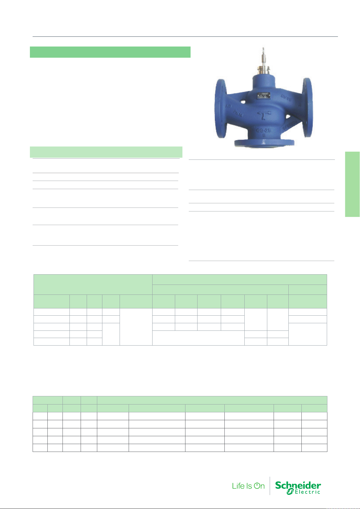
V321
The V321 is a large flanged valve with a stainless steel seat for high
pressure drops.
The valve is suitable for a wide range of mixing applications with hot
or chilled water in heating cooling and air handling systems.
If the valve is used for media at temperatures below 0 °C , it should
be equipped with a heater to prevent ice formation on the valve
stem.
Specifications
Design 3-way plug mixing valve
stem up closed (A port/B-AB open)
Pressure class PN 16
Connection Flange according ISO 7005-2
Flow characteristics
A – AB Equal Percentage
B – AB Linear
DN65…100 30 mm
DN125…150 40 mm
Leakage
A – AB DN65…DN100 <0.05% of Kv
B – AB DN65…DN100 <0.05% of Kv
10. Specialist Products
Stem
DN65…100 Ø10 mm, M10 thread connection
(fitted with Forta stem adaptor to M8)
DN125…150 Ø10 mm, M10 thread connection
(fitted with Hex Bush for M22/M50)
Max. temperature of medium 130 °C
Min. temperature of medium -10 °C
Max. Glycol concentration 50%
Main Construction Materials
Body Grey Cast iron GG25
Stem
DN65…100 Stainless steel SS 1.4571
DN125…150 Stainless steel SS 1.4021
Plug Stainless steel SS 1.4021
Seat Stainless Steel SS 1.4021
Stem Packing EPDM
Speciali Products
10.Legacy and Other
Mixing Application
V321
Part Number DN Kvs ΔPm Rangeability M800 M1500
731 2153 010 65 63 100
731 2157 010 80 100 80 80 180 180 440 40
731 2161 010 100 160
731 2169 010 150 320 60 240
Replacement packing box:
DN65…DN150: 1 001 0822 0
Pre 2007, DN125…DN150
with 18 mm stem dia: 1 001 0821 0
Conversion kit
V321 with old M16 actuator
to Forta connection: 880 0130 000
>30
60
Stem Heater:
DN65…DN100: 880 0110 000
DN125…DN150: 880 0111 000
Replacement Stem adaptors
DN65…DN100: 880 0133 000
DN125…DN150: 1 001 0824 0
Max Close-off Pressure (kPa)
Non-Spring Return Actuators Spring Return
MV15B
(1500N)
140 290 290 700
40 110 110 280
-
M3000
M22
(2200N)
- -
90 340
M50
(5000N)
M700
80
-731 2165 010 125 220
Diverting Application
Size Kvs ΔPm Max Close Pressure, ΔPC (kPa)
DN In. m3/h k Pa Forta M800 Forta M1500/ MV15B Forta M3000 Forta M700 SR M22** M50**
65 2½” 63 100 70 145 350 40 - -
80 3” 100 80 45 60 220 20 - -
100 4” 160 60 25 55 140 - - -
125 5” 220 60 - - - - 55 165
150 6” 320 60 - 35 110
∆Pc = Maximum allowed pressure differential across a closed valve (a function of actuator performance)
∆Pm = Maximum allowed pressure drop across a fully ‘open’ valve (a function of hydronic valve performance)
**M22 and M50 actuators will not fit to valves DN65…100
Note: Never exceed a fluid velocity above 2m/s
F-27878-6 93
Page 94

10. Specialist Products
VZX
The VZX valve utilises a compact actuator for installations with
limited space.
Suitable for a wide range of applications such as heating, cooling
and air handling systems with hot or chilled water.
Specification
Design 2-way plug valve
Pressure class PN 16
Flow characteristic Equal Percentage
Stroke 12.7 mm
Rangeability (Kvs/Kvmin) >50
Speciali Products
10. Legacy and Other
Leakage <0.1% of Kvs
Max. temperature of medium 120 °C
Min. temperature of medium 2 °C
Max. glycol concentration 25%
Connection Screwed BSP to BS21 (Rp)
Main Construction Materials
Body Bronze: Leaded Gunmetal BS1400 LG2
Stem Stainless steel BS970 Grade 303 S42
Plug Copper Alloy BS2874 CZ132 or BS2871 CZ110
Seat Sealing Gland O Ring
Seat Integral with body
Stem packing PTFE Chevrons
Max Close-off Pressure kPa
VZX
Non-Spring Return Actuators
Part Number
VZX4404 Rp 1/2 2.1
VZX4451 Rp 3/4 4.2 1000 1000
VZX4501 Rp 1 8.3 500 500
VZX4551 Rp 1¼ 12.5 300 300
VZX4601 Rp 1½ 21 170 170
VZX4651 Rp 2 33 90 90
Replacement Packing Box: 0626 9 204
Size mm
(inches)
Kvs Rangeability MG350S MZ300S
1600 1600
>50
94 F-27878-6
Page 95
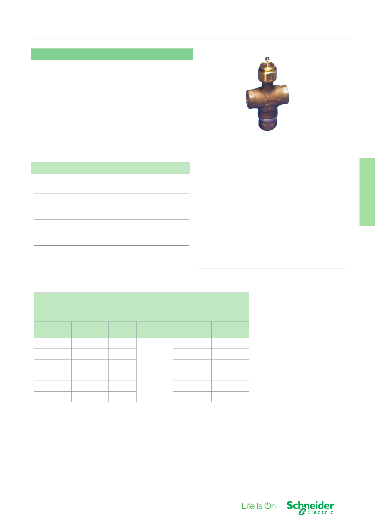
MZX
The MZX is a 3-way valve utilising a compact actuator for installations with limited space.
The valves are suitable for a wide range of mixing applications such
as heating, cooling, air handling and domestic hot water systems.
Specification
Design 3-way plug valve
Pressure class PN 16
Flow characteristic Port 2 Modified Parabolic
Flow characteristic Port 3 Linear
Stroke 12.7 mm
Rangeability (Kvs/Kvmin) >50
Leakage (Ports 2-1) 0.1% max.
Leakage (Ports 3-1) 0.5% max.
Max. temperature of medium 120 °C
Min. temperature of medium 2 °C
10. Specialist Products
Max. Glycol concentration 25%
Connections Rp inter nal pipe thread (BSP to BS21)
Main Construction Materials
Body Bronze: Leaded Gunmetal BS1400 LG2
Stem Stainless steel BS970 Grade 303 S42
Plug Copper Alloy BS2874 CZ132 or BS2871 CZ 110
Sealing Gland O Ring
Seat Top Integral with body
Seat Bottom Copper Alloy BS2874 CZ 132
(12.7…19.05 mm (½” & ¾”) valves)
Seat Bottom Leaded Gunmetal BS1400 LG2
(25.4…50.08 mm (1” to 2” valves)
Stem Packing PTFE Chevrons
Speciali Products
10. Legacy and Other
Max Close-off Pressure (kPa)
MZX
Non-Spring Return Actuators
Part Number
MZX4402 Rp 1/2 2.6
MZX4452 Rp 3/4 4.2 1000 1000
MZX4501 Rp 1 8.3 500 500
MZX4551 Rp 1¼ 12.5 300 300
MZX4601 Rp 1½ 21 170 170
MZX4651 Rp 2 33 90 90
Replacement Packing Box: 0626 9 204
Connection
mm (inches)
Kvs Rangeability MG350S MZ300S
1600 1600
>50
F-27878-6 95
Page 96
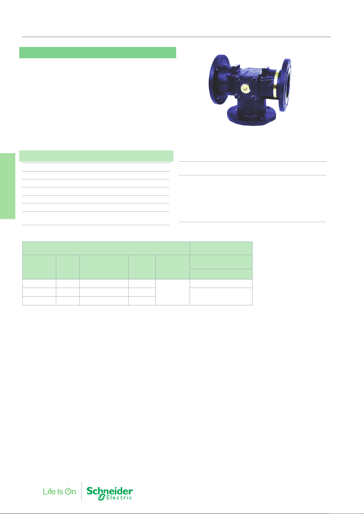
10. Specialist Products
MBF
The MBF is a 3-port flanged rotary shoe valve suitable for both mixing and diverting circuits. The Valve is operated with a linkage kit
and the MD20 Damper actuator.
Specifications
Design 3-way rotary shoe valve
Pressure Class PN6
Flow Characteristic Port 3 Linear
Operating angle 90°
Rangeability (Kvs / Kv
Leakage 0.5% (%of Kvs)
Speciali Products
10. Legacy and Other
Max. temperature of medium 120 °C
Min. temperature of medium 2 °C
) >50
min.
Connection
MBF Flanged BS4504, Table 6/11
Main Construction Materials
Body 12.7…25.4 mm (½”…1”) valves Hot Pressed Brass to BS218
Body 31.75…50.8 (1¼”…2”) valves Close Grained Cast Iron
BS1452 Grade 260
Body 65 mm…100 mm Close Grained Cast Iron BS1452
Grade 260 or 220
Spindle High Tensile Brass to BS2874 CZ114
O Rings EPDM
MBF
Valve Number DN
MBF4732 65 0618 9 510 65
MBF4782 80 0618 9 511 83
MBF4857 100 0618 9 512 125
The MD20A/B is a damper actuator requiring linkage kit (LMD/MBF part number 914 1070 000).
Order auxiliary switches separately:
Type MD-S2 part number: 914 1061 000
Type MD-S1 part number: 914 1060 000.
Spares
Reconditioning Kit
Kvs Rangeability
>50
Max Close-off
Pressure kPa
MD20B
MD20A
20Nm
35
25
96 F-27878-6
Page 97
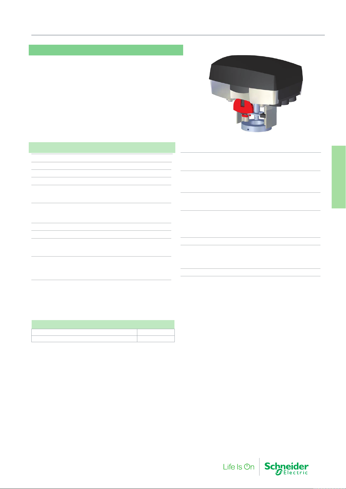
M315
M315 is an electro-mechanical actuator for the control of V294,
V282 and V394 Valves:
M315 utilizes the Forta universal functionality and may be controlled by an increase/decrease signal or by a modulating 0–10 V
control signal.
Specifications
Part Number 880 0070 030
Supply voltage 24 V AC +25%/ -35%, 50–60 Hz
Power consumption 6 VA
Transformer sizing 30 VA
Running time
Modulating 9–25 mm (0.35 - 1 in.) 15 s
Increase/decrease 300 s/60 s
Stroke
Range 9…15 mm ( 0,35…0.59 in.)
Factory set stroke 15 mm (0.59 in.)
Thrust 300 N (67 lbf.)
Duty cycle max. 20% / 60 minutes
Analog input
Voltage 0–10 V
Impedance min 100 kW
Digital inputs VH–VC
Voltage across open input 24 V AC
Current through closed input 5 mA
Pulse time min. 20 ms
10. Specialist Products
Output G1
Voltage 16 V DC ±0.3 V
Load 25 mA, short-circuit proof
Output Y (position feed back signal)
Voltage 2…10 V (0…100%)
Load 2 mA
Wiring Entry
Conduit connection 3 x M20 screwed
Cable gland 1 x 6..12 mm O/D, IP68
Environment
Operating Temperature –10…+50 °C (14 °F…122 °F)
Storage Temperature –10 …+50 °C (14 °F…122 °F)
Humidity max. 90% RH
Enclosure rating IP 54
Material
Housing Aluminium
Cover ABS/PC plastic
Color aluminium/black
Weight 1.8 kg (3.96 lb.)
Speciali Products
10. Legacy and Other
Accessories
S2-Forta Aux switch relay 880 0104 000
Replacement Circuit board M315 1 001 0675 0
F-27878-6 97
Page 98
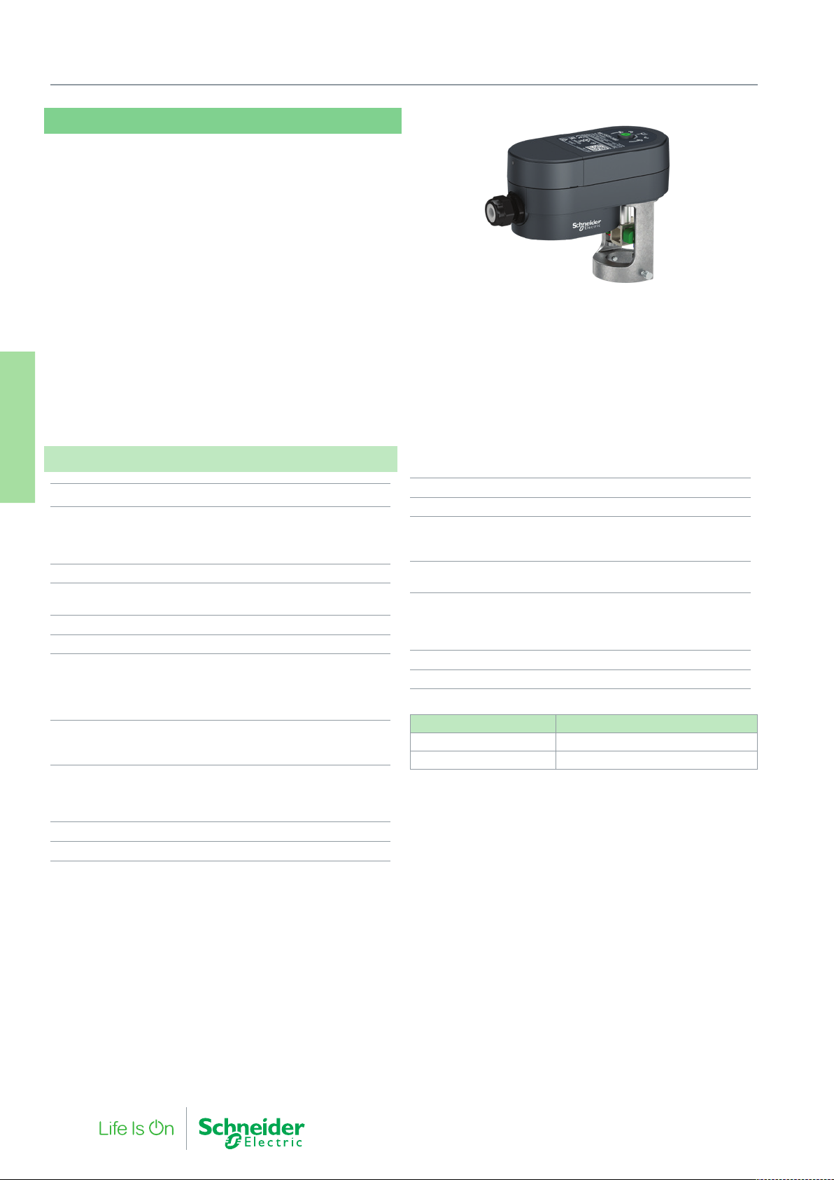
10. Specialist Products
MG350S
The MG350S is a compact electro-mechanical actuator for controlling the VZX and MZX 2-way and 3-way linear globe valves. The
MG350S actuators are primarily designed for applications where the
demands on speed and thrust are relatively small.
• Stable force control with stall protection
• Hysteresis Control - Intelligent response to fluctuating control
signals, extending actuator life and better plant regulation
• High Resolution PCBA and motor transmission for fine valve
plug position and excellent flow control.
• Low power holding
• Auto adaptation to valve end stroke limits upon first power up
• LED status indication
– Tri-color LED for operation, calibration, and alarm
notification
• Removable terminal block and cable gland for ease
installation
Specifications
Speciali Products
10. Legacy and Other
Supply voltage 24 Vac/Vdc ±20% 50/60 Hz
Power Consumption (50Hz)
Running: MG350S-24M
MG350S-24F
Holding (Modulating only)
Transformer sizing (same as Power Consumption)
Running Time 8 s/mm (Full stroke time
Max. Stroke 16.5 mm
Nominal Force 350 N
Control (Floating/Digital)
Dependant upon wiring
3 wire Floating
2 Position on/off
Minimum input pulse
Control (Modulating)
Selectable input signals
Impedance
Environment
Operating Temperature
Storage
Humidity max . 95% RH (NC)
Enclosure rating IP 53 (vertically mounted)
–5…+55 °C (for valve fluid
temperatures up to 130 °C)
24 Vac/Vdc or 0 V
0…10 Vdc, 2…10 Vdc
7.2 VA (3.5 W)
5 VA (3.5 W)
1.2 VA
= 102 sec)
NO or NC
100 msec
min. 100 kΩ
–40…+70 °C
Sound power level max. 30 dBA
Weight (shipping) 0.36 kg
Material
Yoke
Material Housing (Covers)
Mechanical
Manual Override
Position indication Red and blue position markers
Cable Gland wire size 6…12 mm
Conduit hole M20
Part Number Control
MG350S-24M Modulating
MG350S-24F Floating
for hot and cold pipe indication
(green position indicator for
Aluminum
PBT/PC
3 mm Hex
closed valve)
98 F-27878-6
Page 99
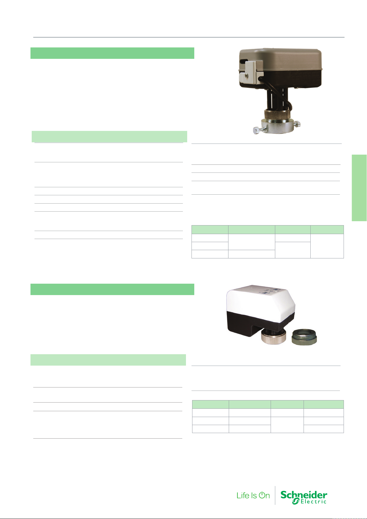
MZ300S
MZ300S actuator is a universal actuator this can drive many
valves with an M30 bonnet. It is supplied with an adapter to drive
theSatchwell VUE, MEU and FEU zone valves, the VP224R PICV
valve and for a specific 230 Vac model, the VZX and MZX globe
valve.
Proportional models are equipped with 3 operation and alarm
LED’s.
Specifications
Power supply
MZ300S-24x 24Vac ±10%
MZ300S-230F 230 Vac ±10%
Power Consumption
MZ300S-24F 2.2VA / 2,2W
MZ300S-24M 3.6VA / 3W
MZ300S-230F 16.2VA / 1.1W
Frequency 50/60Hz
Speed 11.5s/mm at 50Hz - 9.4s/mm at 60Hz
Force 300N
Environment
Operating Temperature -5…55 °C
Storage Temperature -25…65 °C
Protection class II
10. Specialist Products
Connection cable
MZ300-24F / MZ300-230F 3-wire 1.5m
for MZ300S-24M (CEI20-22/II) 5-wire 1.5m
Protection degree IP43
Weight 0.250 kg
Feedback signal (MZ300-24M) 2…10 V reversible according to dip
switch configuration)
Part Number Control signal Power supply Max. stroke
MZ300S-230F
MZ300S-24M
3 point - ON/OFF
0…10 V Modulating
230 Vac
24Vac
16 mmMZ300S-24F
Speciali Products
10. Legacy and Other
MC52
MC52 is an zone actuator designed to provide modulating control
together with the old V354 valves using an adapter. Due to an automatic synchronization function the close-off point is self-adjusting.
Based on a running time of 155 s, valve positioning and flow adjustment is very exact.
Specifications
Range 7 different command field
to be selected with embedded
dip-switches and direct/reverse action
Input voltage 24 VAC 50/60 Hz
Power consumption 1 VA
Speed 18 s/mm (50 Hz) - 15 s/mm (60 Hz)
Environment
Operating Temperature -5…55 °C
Storage Temperature -25…65 °C
Stem force 200 N (45 lbf)
MC52 Actuator Adapter
Max stroke 8.5 mm
Connection cable 3 wires 1.5 m (5 ft)
Protection class IP 43 (for vertical mounting)
Suitable valve V354 - PN 731-5425-000
Part Number Description Control Input voltage
853 2221 010 MC52A-24 Modulating 24 Vac 50/60 Hz
853 1320 000 MC52B-230
853 2320 000 MC52B-24 24 Vac 50/60 Hz
Floating
230 Vc 50/60 Hz
F-27878-6 99
Page 100
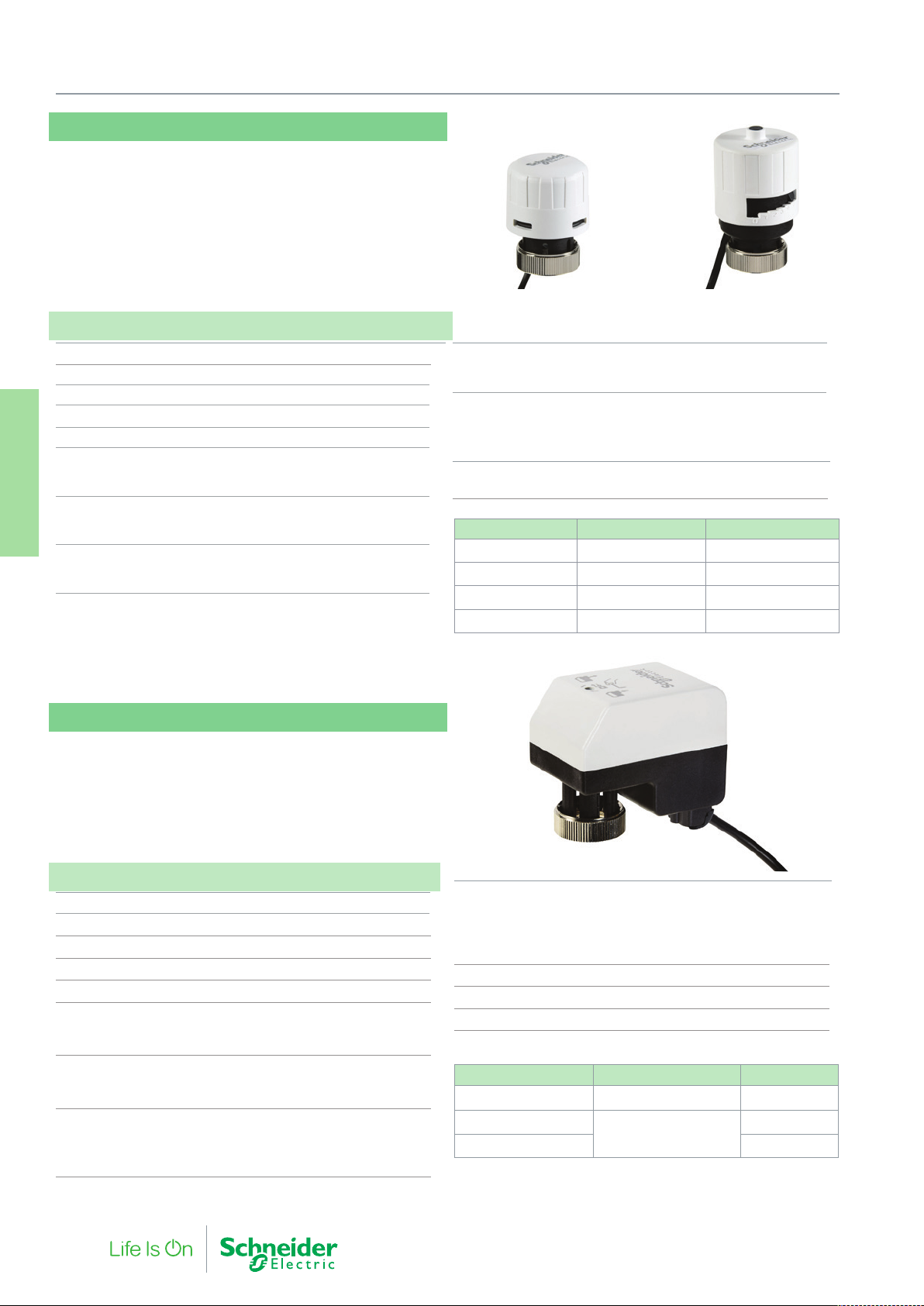
10. Specialist Products
MP140
MP140 is a thermoelectric actuator designed to provide two-position
on/off control together VP223R pressure independent control valves.
The MP140, when connected to the VP223R valve, provides pressure independent flow limiting on/off control. Versions are available
for normally open and normally closed duties.
Specification
Stem force 140 N
Max stroke 4 mm
Coupling ring M30 x 1.5
Power cable 2m twin core (0,35 mm2)
Suitable valve VP223R (DN15…32)
Nominal Power Supply
MZ140-24T 21.8 … 26.8 Vac 50/60 Hz
MZ140-230T 110 … 250 Vac 50/60 Hz
Starting current
24 V models 0.17A
Speciali Products
230 V models 0.25A
10. Legacy and Other
Working current
24 V models 75 mA
230 V models 8 mA
Normally closedNormally open
Power consumption
24 V models 2W
230 V models 2W
Environmental
Ambient working temperature +2…+50 °C
Storage temperature -45…+60 °C
Humidity max. 95% Non-condensing
Material: Fire-resistant case Class V0
Protection class IP 44 / IP41
Part number Function Voltage
MP140NC-24T Normally closed 24 Vac 50/60 Hz
MP140NO-24T Normally open 24 Vac 50/60 Hz
MP140NC-230T Normally closed 110 - 230 Vac 50/60 Hz
MP140NO-230T Normally open 110 - 230 Vac 50/60 Hz
MP200
MP200 is an compact linear actuator for driving the the 5 mm Frese
Optima compact PIBCV and the former VP223R short stroke pressure independent control valve. Versions available as either 3 point
floating or 0…10 Vdc modulating control. A full stroke run time of 60
seconds provides very precise flow control. Stroke indication and
manual override on all models.
Specification
Force 200 N
Stroke Range 3.5 mm…5 mm
Speed 18s/mm (50Hz), 15s/mm (60Hz)
Connection cable 3 wire 1.5 m
Full stroke time on VP223R valve 63s (50Hz), 52s (60Hz)
Recommended controller ‘time out’
function 120% of full stroke time
(floating modules)
Supply Voltage
MP200-24F/MP200-24M 21.6 … 26.4 Vac (50/60Hz)
MP200-230F 207 … 253 Vac (50/60Hz)
Power consumption
MP200-24F 0.6W (0.7VA)
MP200-230F 1W (5VA)
MP200-24M 1.0W (1VA)
100 F-27878-6
Environmental
Working temperature -5 … 55 °C
Storage temperature -25 … 65 °C
Protection class IP43/IP41
(dependant on mounting orientation)
Sound power level 35 dBa
Weight 162g
Humidity Max 95% non-condensing
Part number Control Voltage
MP200-24M Modulating Control 0…10 V
MP200-24F
MP200-230F 230 V
Note: The floating actuators (MP200-24F / MP200-230F) have no end switches for automatic
shut off when the valve is fully open or closed. These floating actuators are intended for
use with controllers with a time out facility. If the floating actuators are to be used with an
on/off thermostat, a separate delay off timer should be used to cut the driven power to the
actuator.
3 Point Floating
24 V
 Loading...