

Page 1
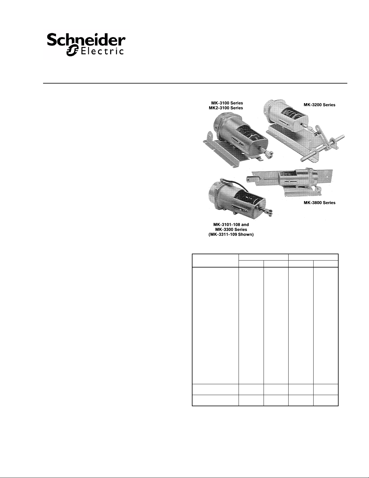
APPLICATION
Proportional pneumatic actuator with 8 in.2 (52 cm2) effective
area used to control dampers, mixing boxes, air valves, etc.,
in heating, ventilating and air conditioning systems,
MK2-31X1 used for high temperatures.
SPECIFICATIONS
Construction:
Housing, Die cast aluminum. Diaphragm, Beaded molded neoprene. MK2-31X1 only -
Beaded molded silicone.
Stroke: See Table 2.
Start Point: Adjustable on most models ± 1 psi, see T a ble 2.
Spring: Retracts actuator shaft on loss of air pressure.
Maximum Air Pressure: 30 psig (207 kPa).
Ambient Temperature Limits:
Shipping, -40 to 160°F (-40 to 71°C).
Operating, -20 to 160°F (-29 to 71°C).
MK2-31X1 only,
Shipping, -40 to 250°F (-40 to 121°C).
Operating, -20 to 250°F (-29 to 121°C), for 30 minute
exposure 450°F (232°C).
Air Connections: 1/8” FNPT.
Mounting: In any position. Mounting bracket (except
MK-3300 Series end mounting) and connector for 5/16" (8
mm) diameter push rod included with actuator.
Dimensions: 12" high x 5-7/8" wide x 5-1/2" deep (305 mm
x 143 mm x 140 mm)
ACCESSORIES
AK-42309-500 Positive positioner and linkage, do not use with
AM-111 Crank arm for 5/16" diameter damper shaft
AM-112 Crank arm for 3/8" diameter damper shaft
AM-113 Crank arm for 1/2" diameter damper shaft
AM-115 Crank arm for 7/16" diameter damper shaft
AM-122 Linkage connector straight type
AM-123 Damper clip
AM-125 5/16" x 20" damper rod
AM-125-048 5/16" x 48" damper rod
AM-132 Ball joint connector
AM-161-3 Damper linkage kit
AM-301 90° mounting bracket for pivot mounting
AM-530 Crank arm for 1/2" diameter damper shaft holes
AM-532 Bolt-on frame lug and damper blade clip kit
AM-533 Actuator shaft extension
AM-534 Pivot stud for pivot mounting
AM-535 Clevis for pivot mounting
AM-536 Mounting plates for pivot mounting on ducts or
AM-545 Rod end connector for 5/16" (10 mm) dia. rods
TOOL-95 Pneumatic calibration tool kit
MK2-3100 series
for 3-1/2
" and 4-1/2" stroke
damper frame
MK-3000 Series, MK2-3000
Series, MK4-3000 Series
Pneumatic Damper Actuators
General Instructions
Table-1 Nominal Damper Area For Proportional Control
Actuator Part
Number
MK-3101
MK-3101-108
MK2-3101
MK4-3101
MK-3111
MK2-3111
MK-3121-109
MK-3121
MK2-3121
MK-3141
MK4-3141
MK-3151
b
MK-3161
MK-3201
MK-3211
MK-3221
MK-3311-109
MK-3321-102
MK-3801
MK4-3801
MK-3811
MK-3821
MK-3841
MK4-3841
MK4-3111
MK4-3811
MK4-3121
MK4-3821
a
For two-position control use proportional rating of the same actuator with
positive positioner. Damper ratings are nominal and based on standard
(not low leakage) dampers at 1" (25.4 mm) W.C. static pressure and 2000
fpm (10 m/s) velocity.
b
Requires 20 psi be available to the actuator .
c
Requires minimum 15 psi be available to the actuator.
d
Proportional control with positioner (8-13 spring, 20 psi supply).
c
c
d
d
Parallel Blades Opposed Blades
2
ft
11.6 1.07 15 1.39
23.2 2.15 30 2.79
34.8 3.23 45 4.18
2
m
2
ft
2
m
a
Printed in U.S.A. 1/10 © Copyright 2010 Schneider Electric All Rights Reserved. F-12586-11
Page 2

Table-2 Specifications.
Maximum Force
Return
Part Number
Nominal
Operating
Range
Starting
Pressure
Nominal
Stroke
a
Stroke
Based on
1.5 psi
(10 kPa)
Pressure
to
Actuator
15 psi
(103 kPa)
Supply
Dual Press.
System
psig kPa psig kPa in. (mm) lb. N lb. N lb. N lb. N lb-in. N-m lb-in. N-m lb-in. N-m
3 (76)
MK-3101-108 3-7.2 21-50 3 ± 1 21 ± 7
MK-3101
MK2-3101
MK4-3101
MK-3111
MK2-3111
3-8 21-55 3 ± 1 21 ± 7
e
3-8 21-55 3 ± 1 21 ± 7 12 53 44 196 56 249 96 427 21 2.37 21 2.37 21 2.37
5-10 34-69 5 ± 1 3 ± 7 28 125 28 125 40 178 80 356 21 2.37 21 2.37 21 2.37
MK4-3111 5-10 34-69 5 ± 1 34 ± 7 28 125 28 125 40 178 80 356 49 5.54 49 5.54 49 5.54
MK-3121
MK-3121-109
MK2-3121
8-13 55-90 8 ± 1 55 ± 7 52 231 4 18 16 71 56 249 7 79 21 2.37 21 2.37
e
Adjustable
2 to 4 (51
to 102)
3 1/2 (89)
Adjustable
2 to 4 (51
to 102)
12 53 50 226 62 276 102 454 18 2.03 18 2.03 18 2.03
12 53 44 196 56 249 96 427 21 2.37 21 2.37 21 2.37
MK4-3121e8-13 55-90 8 ± 1 55 ± 7 52 231 4 18 16 71 56 249 7 79 28 3.16 91 10.28
MK-3141
MK4-3141
MK-3151
MK-3161
e
11-17
3-13 21-90
3-6
21-41
9-12
62-83
3-6
21-41
76-117
MK-3201 3-8 21-55 3 ± 1 21 ± 7 90o
MK-3211 5-10 34-69 5 ± 1 34 ± 7 28 125 28 125 40 178 80 356 21 2.37 21 2.37 21 2.37
MK-3221 8-13 55-90 8 ± 1 55 ± 7 52 231 4 18 16 71 56 249 7 .79 21 2.37 21 2.37
MK-3311-109 5-10 34-69 5 ± 1 34 ± 7 3-1/2 (89)
MK-3321-102 8-13 55-90 8 ± 1 55 ± 7 52 231 4 18 16 71 56 249 7 .79 21 2.37 21 2.37
MK-3801
MK4-3801
3-8 21-55 3 ± 1 21 ± 7
e
MK-3811 5-10 34-69 5 ± 1 34 ± 1 28 125 28 125 40 178 80 356 21 2.37 21 2.37 21 2.37
MK4-3811 5-10 34-69 5 ± 1 34 ± 1 28 125 28 125 40 178 80 356 49 5.54 49 5.54 49 5.54
MK-3821 8-3 55-90 8 ± 1 55 ± 1 52 231 4 18 16 71 56 249 7 79 21 2.37 21 2.37
MK4-3821e8-13 55-90 8 ± 1 55 ± 1 52 231 4 18 16 71 56 249 7 79 28 3.16 91 10.28
MK-3841
MK4-3841
a
Factory setting required for published operating range.
b
Force and torques based on factory set stroke and starting pressure.
c
Nominal torque for actuators without positive positioner is based on 1.5 psi pressure change at the actuator.
d
Adjust pressure reducing valve so that listed pressures are available at the actuator.
e
Factory installed positive positioner (AK-42309-500) start point adjustable 2 to 10 psi with range adjustable 2 to 10 psi.
e
3-13 21-90
3
non-adj
3-6
3-6
3
non-adj
21
non-adj
21 to
41
21 to
41
21
non-adj
2-3/4 (70)
Adjustable
2 to 2-3/4
(51 to 70)
Rotation
Typical,
Adjustable
1.2 to 4.4
(30 to 111)
Adjustable
2 to 4 (51
to 102)
3-1/2 (89)
Adjustable
2 to 4 (51
to 102)
12 53 4 18 16 71 56 249 7 79 21 2.37 21 2.37
12 53 12 53 24 107 64 285 21 2.37 21 2.37 21 2.37
12 53 0 0 0 0 24 107 0 0 0 0 21 2.37
12 53 44 196 56 249 96 427 21 2.37 21 2.37 21 2.37
28 125 28 125 40 178 80 356 21 2.37 21 2.37 21 2.37
12 53 44 196 56 249 96 427 21 2.37 21 2.37 21 2.37
12 53 4 18 16 71 56 249 7 79 21 2.37 21 2.37
b
Power Stroke
15 psi
(103 kPa)
Supply
Single
Press.
d
System
20 psi
(138 kPa)
Supply
Single or
Dual Press.
System
15 psi
(103 kPa)
Supply Dual
Press.
System
Nominal Torque
Proportional Control
15 psi
(103 kPa)
Supply
Single Press.
System
c
b
20 psi
(138 kPa)
Supply
Single or
Dual Press.
System
d
2 © Copyright 2010 Schneider Electric All Rights Reserved. F-12586-11
Page 3
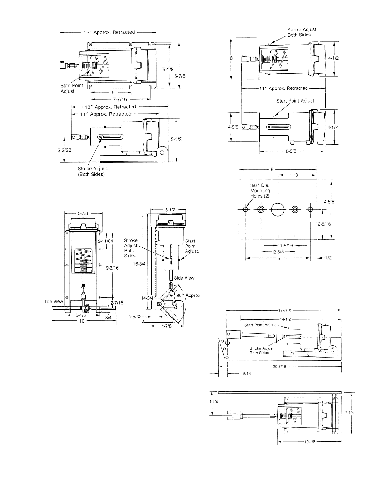
Figure-1 MK-3100 Series Dimensions.
Mounting plate for MK-3101-108 and MK-3300-102
Series Actuators
Figure-2 MK-3200 Series Dimensions.
1
Figure-3 MK-300 Series Dimensions2.
1.
All dimensions shown in the Instruction Sheet are in inches.
F-12586-11 © Copyright 2010 Schneider Electric All Rights Reserved. 3
Figure-4 MK-3800 Series Dimensions.
2.
Typical Model shown. Linkage, and air connection details may vary from
Model to Model.
Page 4
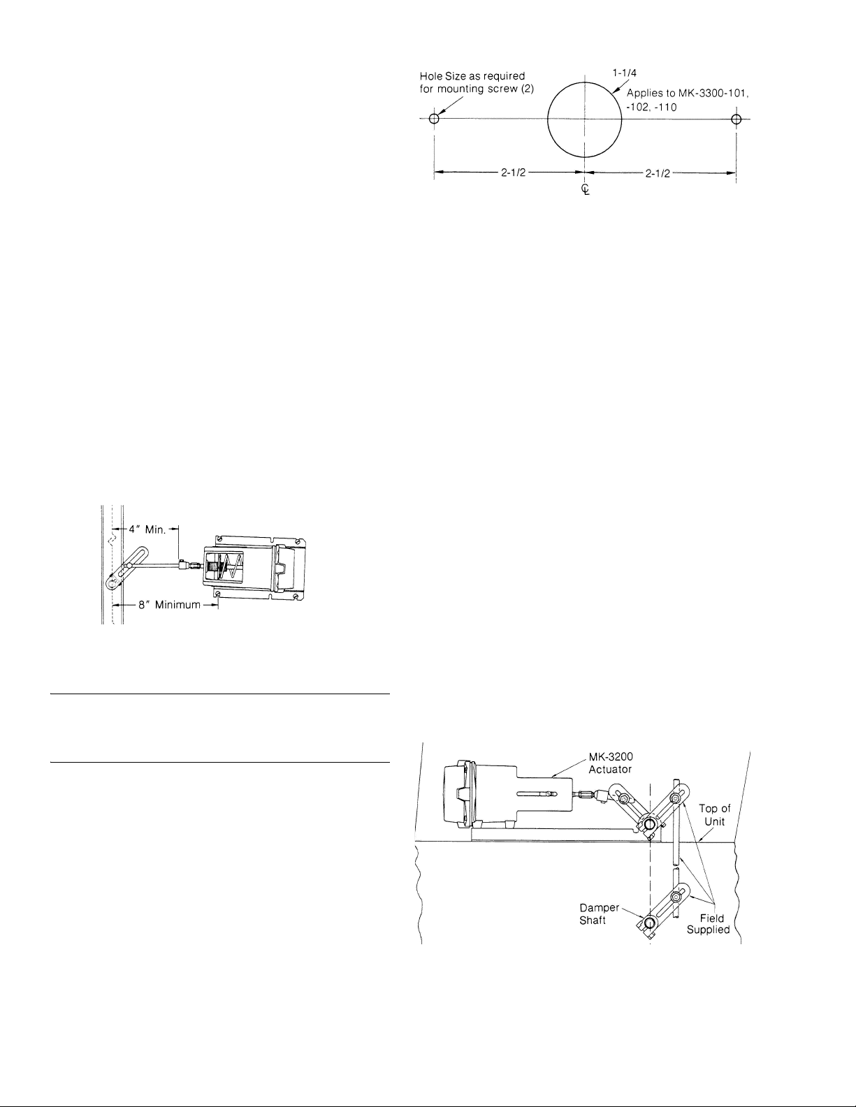
MK-3100 Series Typical Mounting
Accessories Required for Mounting Per Figure 5
1 — AM-113 Crank arm.
1 — AM-122-0-0-2 or AM-132-0-0-2 ball joint.
1 — AM-125 link rod 5/16-inch x 20 inches.
To mount proceed as follows. Refer to Figure 5.
1. Measure a minimum of 8 inches from damper shaft in the direction of actuator location.
2. Hold actuator up to duct with actuator shaft approximately 1-1/2 inches above (N.C.) or below (N.O.) damper shaft and mark mounting holes.
3. With drill or punch, pierce holes marked in Step 2.
4. Mount actuator to duct.
5. Attach ball joint to crank arm at approximately 2-1/2 inches from center of shaft hole.
6. Attach crank arm to damper shaft at approximately 45° angle, from vertical, toward actuator with damper in the normal actuator retracted position.
7. Connect actuator ball joint to crank arm ball joint with 5/16-inch diameter rod. Cut off excess rod.
8. Refer to Checkout.
Figure-5 MK-3100 Series Typical Mounting.
MK-3300 Series Typical Mounting
Note: MK-3300 Series Models are designed for Mixing Box
applications. Mounting, Linkage, and air connection details
vary among Models. See Actuator Selection Sheet F-13795
for more information.
Figure-6
MK-3200 Series Typical Mounting
Accessories Required for Mounting Per Figure 7
2 — AM-113 crank arm.
2 — AM-122-0-0-2 or AM-132-0-0-2 ball joint.
1 — AM-125 link rod 5/16-inch x 20 inches.
To mount proceed as follows. Refer to Figure 7.
1. Locate actuator on a surface perpendicular to the damper shaft, with the actuator rotary shaft approximately in line with the damper shaft.
2. Hold actuator up to duct and mark mounting holes.
3. With drill or punch, pierce holes marked in Step 2.
4. Mount actuator to duct.
5. Attach crank arm to actuator shaft at approximately 45° angle.
6. Attach ball joint to crank at approximately 2-1/2 inches from center of shaft hole.
7. Attach crank arm to damper shaft an approximately 45° angle, from vertical, toward actuator with damper in the normal actuator retracted position.
8. Attach ball joint to crank arm at approximately 2-1/2 inches from center of shaft.
9. Connect actuator ball joint to crank arm ball joint with 5-1/6-inch diameter rod. Cut off excess rod.
10. Refer to Checkout.
Accessories Required for Mounting Per Figure 8
1 — AM-125 link rod 5/16-inch x 20 inches.
1 — Connector as required for connection to driven device.
To mount proceed as follows. Refer to Figures 6 and 8.
1. Drill holes in mounting surface as shown in Figure 6.
2. Mount actuator.
3. Connect actuator.
4. Refer to Checkout.
4 © Copyright 2010 Schneider Electric All Rights Reserved. F-12586-11
Figure-7 MK-3200 Series Typical Mounting.
Page 5
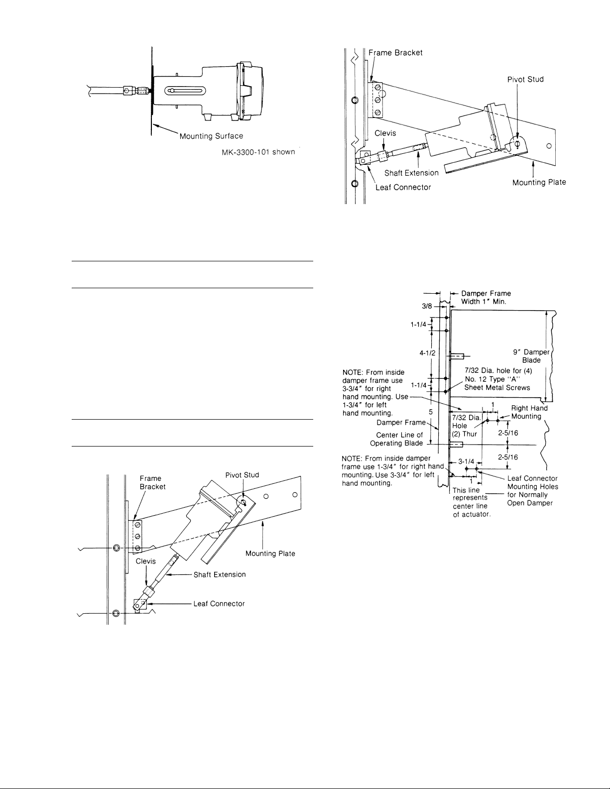
Figure-8 MK-3300 Typical Mounting.
MK-3800 Series Typical Mounting
Accessories Required for Mounting of Actuator Per Figure 9 through 11
1— AM-532 bolt-on frame bracket kit.
Note: Bracket kit includes the frame bracket, leaf connector,
and necessary screws or bolts and nuts.
To install the actuator proceed as follows:
1. Prepare the damper by drilling necessary holes, etc. See Figures 11 and 15 for bolt-on bracket.
2. Attach bracket and leaf connector to damper.
3. Attach actuator mounting plate to damper bracket.
4. Install pivot stud to actuator mounting plate.
5. Install actuator to pivot stud and connect clevis to blade connector.
Note: Adjust clevis as needed to align clevis and leaf
connector.
Figure-10 MK-3800 Series Typical Mounting,
Normally Closed.
Preparing Damper for Frame Mounting of Actuator
Refer to Figures 11 and 15 for required holes, etc. for AM-532.
Figure-11 Typical Bolt-On Bracket Mounting.
Accessories Required for Mounting of Actuator Per Figure 12
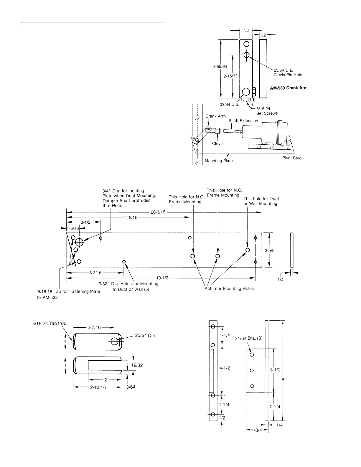
1 — AM-530 crank arm.
To install proceed as follows:
1. Attach mounting plate to duct or wall with damper shaft
protruding through locator hole in mounting plate. If this is
Figure-9 MK-3800 Series Typical Mounting, Normally Open.
F-12586-11 © Copyright 2010 Schneider Electric All Rights Reserved. 5
not possible, additional shaft extensions may be used to
allow locating the actuator farther from the damper shaft.
Each extension provides 4 inches of extension to the
actuator shaft and may be used in multiples.
2. Install the pivot stud to the mounting plate.
3. Install actuator on pivot stud.
4. Install crank arm on damper shaft at approximately 45° angle from vertical toward actuator.
Page 6
Note: Figure 12 shows position for normally closed.
5. Manually position damper to full retracted actu ator position and tighten crank arm in position described in Step 4.
6. Connect clevis to crank arm in hole closest to damper shaft. If necessary adjust clevis and/or extensions.
7. Refer to Checkout.
Figure-12 MK-3800 Typical External Pivot Mounted.
Figure-13 Mk-3800 Series Mounting Plate.
Figure-14 MK-3800 Series Clevis.
Figure-15 AM-532 Bolt-On Frame Bracket.
6 © Copyright 2010 Schneider Electric All Rights Reserved. F-12586-11
Page 7
CHECKOUT
After installation, the actuator should be checked to insure
proper damper operation. To check the actuator and linkage,
proceed as follows:
1. Check the linkage with the actuator in the retracted
position for proper return force. The actuator should be
linked so that on a normally closed application, the damper
is closed with no more than 1/16-inch compression of the
spring. (The actuator shaft would return an additional
1/16-inch if the linkage were disconnected.) For a normally
open application, the actuator should be linked with the
actuator fully retracted.
2. Apply air pressure to the actuator or pilot port of a
positioner and check the linkage as follows. On a
normally closed application, the damper should be just
full open when the actuator piston reaches the stops in
the actuator. On a normally open application, the damper
should reach the closed position with no more than
1/16-inch stroke remaining to reach the actuator stops.
3. The above can be obtained through adjustment of the ball joint in the crank arms or by adjustment of the actuator stops. The amount of thread engagement of the actuator ball joint or extension shaft may also be used to assist in proper linking.
Connection of Air Line: On pivot mounting arrangements,
Figures 9, 10 and 12, control air lines MUST be terminated at
the actuator with at least 6 inches of flexible tubing to allow for
pivoting of the actuator. On mounting arrangements, Figures
5, 7 and 8, control air lines may be connected directly with
either copper or plastic tubing, as required by application.
Caution: On MK2-31X1 Series, metal connectors and tubing
must be used.
Adjustable Starting Pressure: Actuators are available with
adjustable starting pressure. To adjust the starting pressure,
turn adjusting nut supporting the spring clockwise to increase
and counterclockwise to decrease the starting pressure. Each
rotation of the adjusting nut changes the starting pressure .04
psi (.28 kPa).
Adjustable Stroke Length: Stroke length is determined by
the two stops located on either side of the actuator. Stops are
set for 3-1/2-inch stroke. mark this point and measure toward
the diaphragm end of the actuator to reduce the stroke or
away from the diaphragm end to increase the stroke.
Maximum stroke length is 4 inches. By increasing the stroke
length, the force available to resist an opposing force is
decreased while decreasing the stroke length increases this
force.
Diaphragm Replacement: If the actuator diaphragm should
leak, it may easily be replaced by removing the four screws
holding the top power housing. Make sure that shaft swivel
joint is in place on the end of the shaft. Remove the screws
and old diaphragm. Roll the new diaphragm inside out and
install over the piston making sure the circular bead is facing
up. Put the top power housing back in place making sure the
bead on the diaphragm is in the housing groove and the screw
holes are lined up. Tighten housing screws.
UNITS WITH FACTORY MOUNTED POSITIVE POSITIONERS
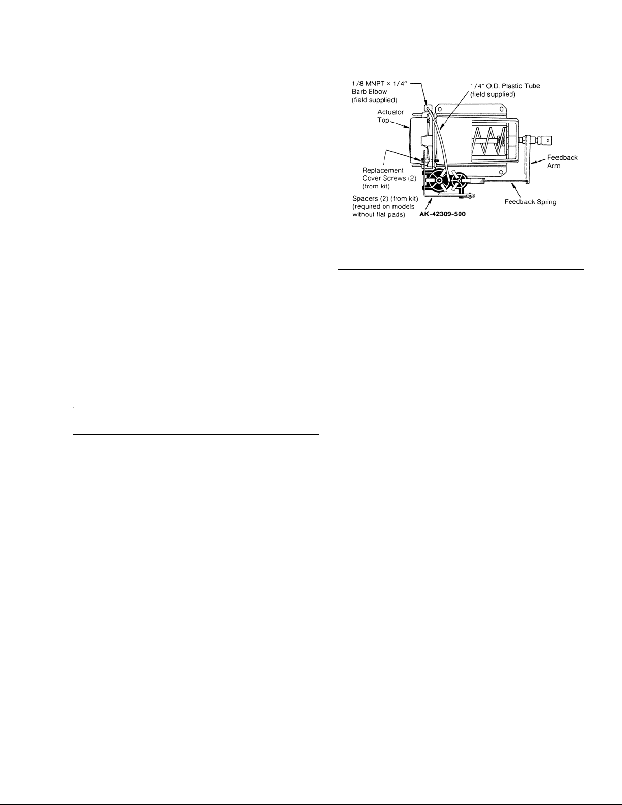
Figure-16 Typical Factory Mounted Positioner.
For Actuators with Positioners:
Note: If actuator is frame pivot mounted, the actuator must
be mounted to the left-hand frame. If actuator is mounted
external, Figure 12 must be on right-hand side of duct.
Install fittings required in Ports 2 and 3.
ADJUSTMENTS
Refer to Figure 16.
Range Adjustment: Adjustable 2 to 10 psig (14 to 69 kPa).
Factory set at 5 psig (34 kPa). Range is the pressure change
required to produce full actuator stroke.
If adjustment is required (see Figure 16), with a small
screwdriver loosen screw on range slider approximately 1/2
turn.
Move the graduated range slider until desired pressure mark
lines up with center of screw and tighten screw.
Start Point: Adjustable 2 to 10 psig (14 to 69 kPa). S tart point
is the pressure at which the actuator just begins to extend.
See Figure 16.
Connect main air supply to Port 3 and a variable air supply to
Port 2.
1. Adjust variable air supply on Port 2 to desired start point pressure.
2. Adjust the start point screw with small screwdriver until actuator just starts to extend.
3. Gradually raise pressure on Port 2 until actuator is fully extended, and readjust range slider to obtain desired range if further adjustment is necessary.
4. Remove variable air supply from Port 2 and connect to controller output.
F-12586-11 © Copyright 2010 Schneider Electric All Rights Reserved. 7
Page 8

On Octo ber 1st, 2009, TAC became the Buil ding s business of i ts parent c om pany Sch neider Electric. This document reflects the visual ident ity of Schneider El ectric,
ho wever the re rema ins ref erences to TAC as a co r p or ate br and in the body copy. As each document i s updated, the body co py will be cha nged to reflec t appropriate
Figure-17 Typical Piping Diagram with Factory Mounted Positive
Note: If slave damper actuators
are to be controlled, tee into the
tubing from Port 1 to the
actuators. All dampers must be
mechanically interconnected.
Positioner.
corpo rate br a nd ch a nges.
Copyright 2010, Schneider Electric
All brand names, trademarks and registered
trademarks are the property of their respective
owners. Information contained within this
document is subject to change without notice.
F-12586-11
 Loading...