

Page 1
Installation and Operation
bu001b
™
Back-UPS
Inventory Safety and General Information
Pro BR1000G
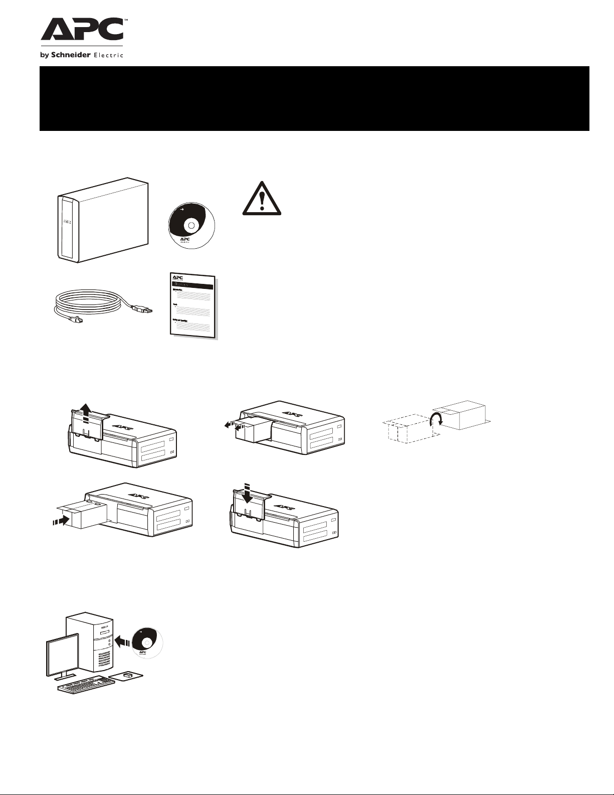
Inspect the package contents upon receipt. Notify
the carrier and dealer if there is any damage.
User Do cume ntati on
Read the Safety Guide supplied with this unit before
installing the UPS.
• This UPS is intended for indoor use only.
not operate this UPS in direct sunlight, in contact with fluids, or where th
• Do
is excessive dust or
•
Be sure the
proper v
•
The battery typically lasts
battery
f
requent short duration discharges will shorten battery life
Connect the
•
protect
air vents on the UPS are not blocked. Allow adequate sp
entilation.
life. Elevated ambient temperatures, poor quality AC power, an
UPS power cable directly to a wall outlet. Do not use surg
ors or extension cords.
humidity.
for three to five years. Environmental factors
ere
ace for
impact
d
e
Connect the Battery
bu059a
bu057a
bu055a
bu058a
bu060a
Install PowerChute
PowerChute Personal Edition software provides automatic file saving and shutdown of your computer
User Do cu me n ta t i on
in the event of a power failure. Use the cable supplied with the Back-UPS to connect the data port on
the Back-UPS to the USB port on your computer. Place the CD into your computer, and follow the onscreen instructions.
™
Personal Edition Software
Page 2
Connect the Equipment
bu126a
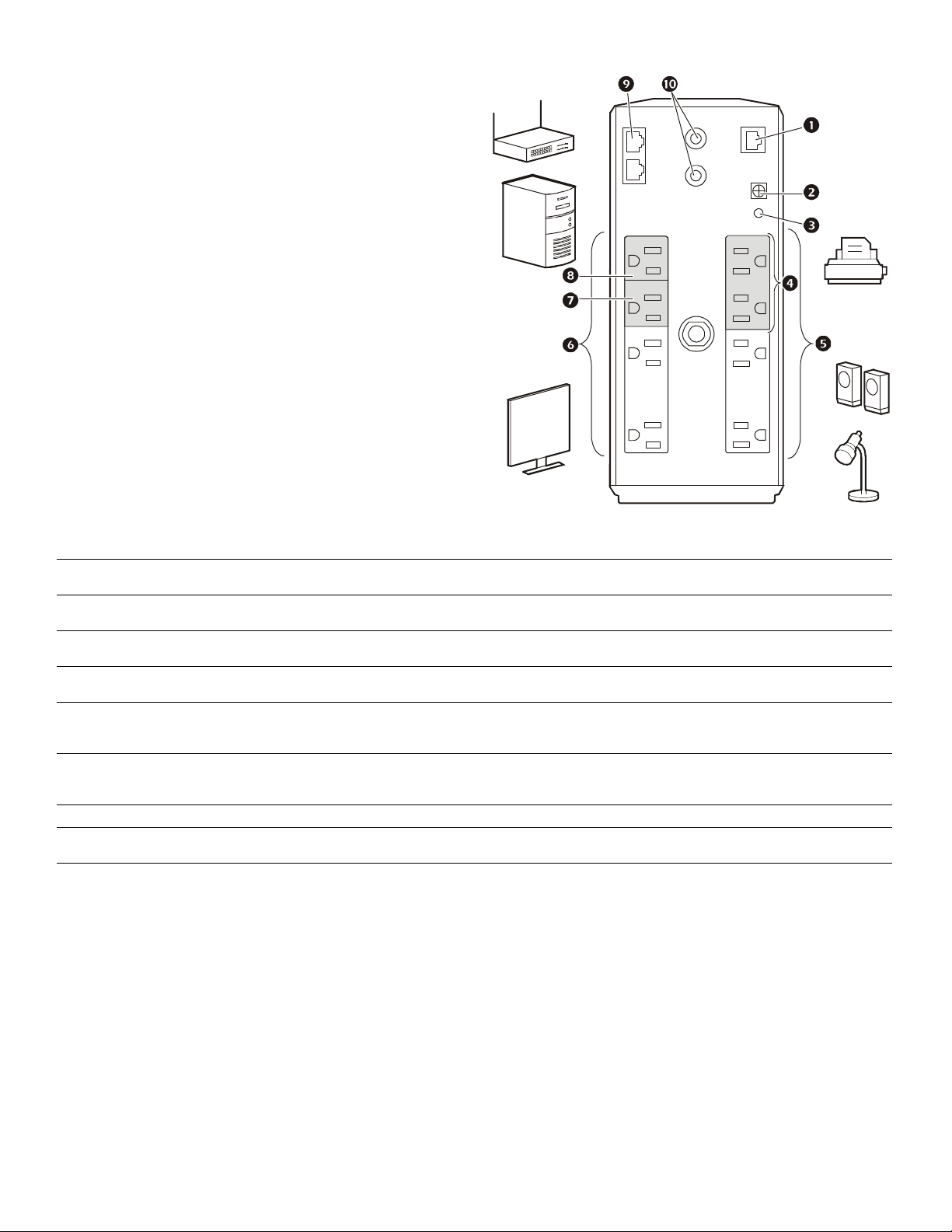
Battery Backup and Surge Protected outlets
When the Back-UPS is receiving input power, the Battery
Backup with Surge Protection outlets will supply power to
connected equipment. During a power outage or other AC
problems, the Battery Backup outlets receive power for a
limited time from the Back-UPS.
Connect equipment such as printers, fax machines,
scanners, or other peripherals that do not need battery
backup power to the Surge Protection Only outlets. These
outlets provide full-time protection from surges even if the
Back-UPS is switched OFF.
Master and Controlled outlets
To conserve electricity, when the device connected to
Master Outlet goes into Sleep or Standby mode, or turns
Off, the Controlled device(s) will shut down as well,
saving electricity.
Connect a master device, such as a desktop computer or
audio/visual receiver to the Master outlet. Connect
peripheral devices such as a printer, speakers, or a scanner
to the Controlled outlets.
USB and Serial Data port To use PowerChute Personal Edition, connect the supplied USB software cable or an optional
Ground screw Connect the ground lead of additional surge suppression devices such as network and data line
Building Wiring Fault indicator If this indicator is illuminated, there is a problem with the wiring in the building. Contact an
Surge Protected outlets,
controlled by the Master outlet
Surge Protected outlets These outlets provide full-time protection from surges, even if the Back-UPS is off. Connect
Battery Backup outlets with
Surge Protection
Battery Backup outlets with
Surge Protection, controlled by
the Master outlet
Master outlet Connect the master device to this outlet, in most scenarios, this will be the main computer.
In/Out Ethernet
surge-protected ports
Coaxial ports with surge
protection
serial cable (not supplied).
surge protectors.
electrician immediately and do not use the Back-UPS.
These outlets are protected from electrical surges, and will disconnect from AC power during a
power outage, or if the Master device goes into Sleep or Standby mode.
equipment such as printers and scanners that do not require battery backup protection.
During a power outage or other AC problems, the Battery Backup outlets receive power for a
limited time from the Back-UPS. Connect critical equipment such as desktop computer,
computer monitor, modem or other data sensitive devices into these outlets.
These outlets will supply battery power to the connected equipment during a power outage.
Power will be disconnected to these outlets if the Master device goes into Sleep or Standby
mode. Connect equipment such as a computer monitor to these outlets.
Use an Ethernet cable to connect a cable modem to the IN port, and connect a computer to the
O
UT port.
Connect a cable modem or other equipment with coaxial jacks.
Back-UPS Pro BR1000G2
Page 3
Operation
Power Saving Function
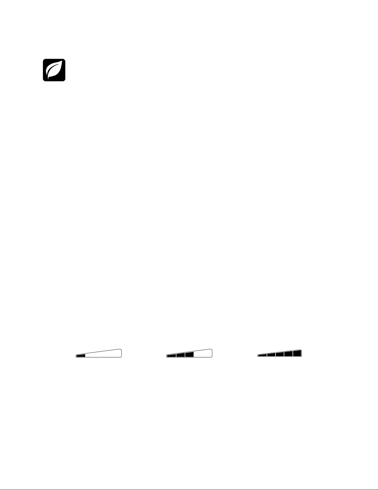
To conserve electricity, configure the Back-UPS to recognize a Master device, such as a desktop computer or an
A/V receiver, and Controlled peripheral devices, such as a printer, speakers, or a scanner. When the Master device
goes into Sleep or Standby mode, or is switched OFF, the Controlled device(s) will be switched off as well, saving
electricity.
NOTE: Devices that provide network services such as routers, modems or wireless printers should not be plugged into the
Controlled outlets. This product ships with the Power Saving feature Disabled. To enable this feature follow the instructions
below.
Enable the Power Saving function. Press and hold MUTE and DISPLAY simultaneously for two seconds.
The Back-UPS will beep to indicate that the feature is enabled. The leaf icon on the display will illuminate.
Disable the Power Saving function. Press and hold MUTE and DISPLAY simultaneously for two seconds. The Back-UPS
will beep to indicate that the feature is disabled. The leaf icon on the display will darken.
Setting the threshold. The amount of power used by a device in Sleep or Standby mode varies between devices. It may be
necessary to adjust the threshold at which the Master outlet signals the Controlled outlets to shut down.
1. Ensure a master device is connected to the Master outlet. Put that device into Sleep or Standby mode, or turn it OFF.
2. Press D
beeps three
3. The Back-UPS will now recognize the threshold level of the Master device and save it as the new threshold setting.
Power Saving Display
The display interface can be configured to be continuously illuminated, or to save energy, it can be configured to darken after a
period of inactivity.
ISPLAY and MUTE simultaneously and hold for six seconds, until the leaf icon flashes three times and the Back-UPS
times.
1. Full Time Mode: Press and hold DISPLAY for two seconds. The display will illuminate and the Back-UPS will beep to
confirm the Full Time m
2.
Power Saving Mode: Press and hold DISPLAY for two seconds. The display will darken and the Back-UPS will beep to
confirm the Power Saving mode. While in Power Saving Mode, the display will illuminate if a button is pressed, it
darkens after 60 seconds of
ode.
no activity.
Unit sensitivity
Adjust the sensitivity of the Back-UPS to control when it will switch to battery power; the higher the sensitivity, the more often
the Back-UPS will switch to battery power.
1. Ensure the Back-UPS is connected to AC power, but is OFF.
2. Press and hold the P
UPS is in programming mode.
3. Press POWER again to rotate through the menu options. Stop at selected sensitivity. The Back-UPS will beep to confirm the
selection.
Generator Sensitivity Default Sensitive Loads
Low sensitivity Medium sensitivity (Default) High sensitivity
Input voltage is extremely low or
high. (Not recommended for
computer loads.)
OWER button for six seconds. The LOAD CAPACITY bar will flash on and off, indicating that the Back-
78-142 Vac 88-139 Vac 88-136 Vac
The Back-UPS frequently switches to
battery power.
The connected equipment is
sensitive to voltage fluctuations.
then
Back-UPS Pro BR1000G
3
Page 4
Front Panel Buttons and Display Interface
bu109 e
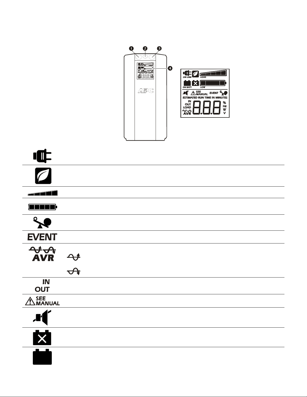
Use the three buttons on the front panel of the Back-UPS and the display interface to configure the Back-UPS.
Front panel
Mute button
Power On/Off button
Display button
Display interface
On Line: The Back-UPS is supplying conditioned AC power to connected equipment
Power-Saving: Master and Controlled outlets are enabled, saving power when the master device goes into
sleep or standby mode
Load Capacity: The load is indicated by the number of sections illuminated, one to five. Each bar represents
20% of the load.
Battery Charge: The battery charge level is indicated by the number of sections illuminated. When all five
blocks are illuminated, the Back-UPS is at full charge. When one block is filled, the Back-UPS is near the end of
its battery capacity, the indicator will flash and the Back-UPS will beep continuously.
Overload: The power demand from the load has exceeded the capacity of the Back-UPS.
Event: The event counter shows the number of events that occurred that caused the Back-UPS to switch to on-
battery operation.
Automatic Voltage Regulation: The Back-UPS can compensate for high or low input voltage.
When illuminated, the Back-UPS is compensating for low input voltage.
When illuminated, the Back-UPS is compensating for high input voltage.
In: Input voltage.
Out: Output voltage.
System Faults: The system has a fault. The fault number will illuminate on the display interface. See "System
Faults" on page 5.
Mute: If the line through the speaker icon is illuminated, the audible alarm has been turned off.
Replace Battery: The battery is nearing the end of its useful life. Replace the battery.
On Battery: The Back-UPS is supplying battery backup power to the connected equipment, it will beep four
times every 30 seconds.
Back-UPS Pro BR1000G4
Page 5
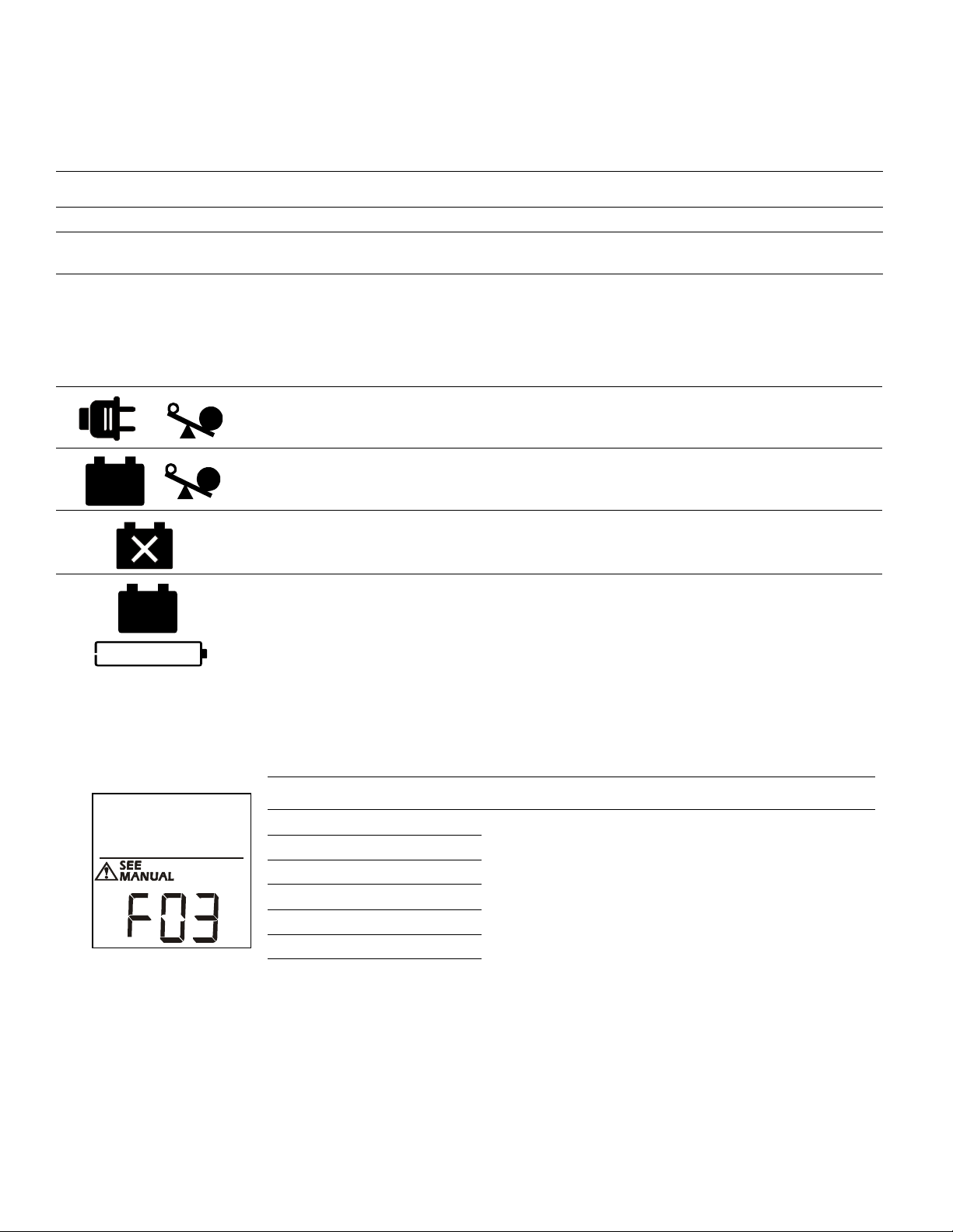
Warnings and System Faults
bu088a
Audible Warnings
Four Beeps Every 30 Seconds
Continuous Beeping
Continuous tone
Chirps every 2 Seconds with the
Load Capacity Bar flashing
Chirps for 1 Minute every 5 hours
Warning Icons
If these icons are
illuminated... This may be the problem.
The Back-UPS is operating on AC power, but is overloaded. Disconnect one of the items connected to
the Back-UPS. If the Overload icon stops flashing, the Back-UPS is no longer overloaded and will
continue to operate normally.
The Back-UPS is operating on battery power, but is overloaded. Disconnect one of the items connected
to the Back-UPS. If the Overload icon stops flashing, the Back-UPS is no longer overloaded and will
continue to operate normally.
The Back-UPS is operating on AC power, but the battery is not functioning properly. Contact Schneider
Electric IT (SEIT) Customer Service to order a replacement battery. See "Replacement Battery" on
page 8.
The Back-UPS is operating on battery power and the battery power is getting low. Shut down all
connected equipment to avoid losing an unsaved data. When possible, connect the Back-UPS to AC
power to recharge the battery.
Back-UPS is running on battery. You should consider saving any work in progress.
Low battery condition and battery run-time is very low. Promptly save any work in progress, exit
all open applications, and shut down the operating system.
Battery Backup outputs are overloaded.
Battery is disconnected.
Battery fails the automatic diagnostic test and should be replaced.
System Faults
The Back-UPS will display these fault messages. For faults F01 and F02, contact SEIT Technical Support.
On-Battery Overload
F01
On-Battery Output Short
F02
On-Battery Xcap Overload
F03
Clamp Short
F04
Charge Fault
F05
Relay Welding
F06
Temperature
F07
Fan Fault
F08
Internal Fault
F09
Turn the Back-UPS off. Disconnect non-essential equipment
from the Battery Backup outlets and the turn Back-UPS on.
Turn the Back-UPS off. Disconnect non-essential equipment
from the Battery Backup outlets and the turn Back-UPS on.
Faults F03-F09 cannot be corrected by the user, contact SEIT
Technical Support for assistance.
Back-UPS Pro BR1000G
5
Page 6
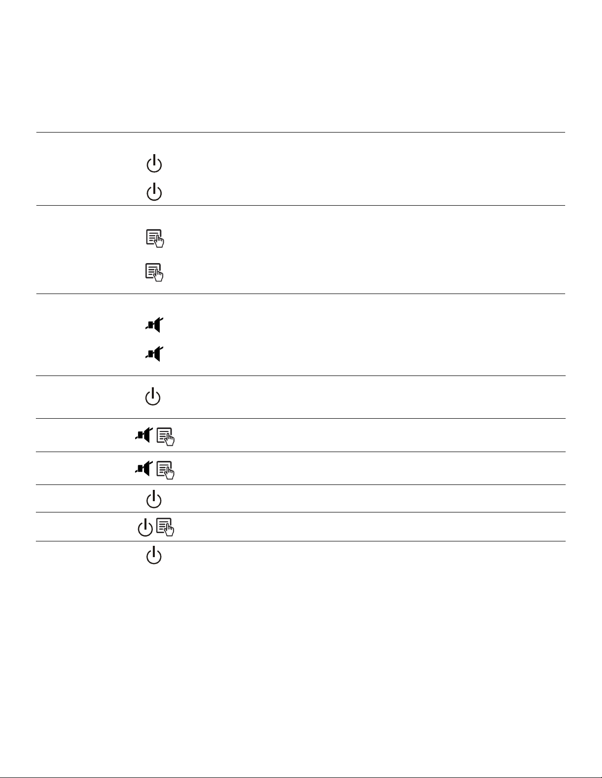
Function Button Quick Reference
Function Button
Power
Power On
Power Off
Display
Status Inquiry
Full-Time/PowerSaving mode
Mute
Event Specific
General Status
Enable/Disable
Sensitivity
Master/Controlled
outlet Enable/Disable
Master/Enable
Threshold Calibration
Self-Test (manual)
Timing
(seconds)
0.2 Off
2On
0.2 On
2On
0.2 On Disable any audible alarms caused by an event.
2On
6Off
2On
6On
6On
UPS
Status Description
Press P
available, the Back-UPS will run on battery power.
The Back-UPS is not receiving input AC power, but is providing surge
protection.
Verify the status or condition of the Back-UPS. The LCD will illuminate for 60
seconds.
The LCD will illuminate and the Back-UPS will beep to confirm the Full-Time
mode. The LCD will darken and the Back-UPS will beep to confirm the
Power-Saving mode. While in Power-Saving Mode, the LCD will illuminate if
a button is pressed, then darkens after 60 seconds of no activity.
Enable or disable the audible alarms. The Mute icon will illuminate and the
Back-UPS will beep one time. The Mute function will not activate unless the
Back-UPS is operating on battery power.
The Load Capacity icon will blink, indicating that the Back-UPS is in
programming mode. Use the POWER button to scroll through Low, Medium,
and High, stop at selected sensitivity. The Back-UPS will beep to confirm
selection. See Configuration for details.
The leaf icon will darken indicating that the Master Outlet feature is disabled
or illuminate to indicate the Master Outlet feature is enabled. The Back-UPS
will beep once.
While calibrating the threshold setting, the device connected to the Master
Outlet should be turned off or placed in Standby or Sleep mode. Upon
completion, Power-Saving icon will flash 3 and beep 3 times.
The Back-UPS will perform a test of the internal battery. Note: This will
happen automatically when the Back-UPS is turned ON.
OWER to start receiving input AC power. If AC input power is not
Event Reset
Fault Reset
0.2 On
2 Fault
When the Event screen is visible, press and hold D
POWER, to clear the failure event counter.
After a fault has been identified, press P
and return to standby status.
Back-UPS Pro BR1000G6
OWER to remove the visual indication
ISPLAY, then press
Page 7

Troubleshooting
Problem Possible Cause Corrective Action
Back-UPS will not switch on. The Back-UPS is not connected to AC power. Ensure that the Back-UPS is securely connected to an
AC outlet.
The circuit breaker has been tripped. Disconnect non-essential equipment from the Back-
UPS. Reset the circuit breaker. Re-connect equipment
one item at a time. If the circuit breaker is tripped again,
disconnect the device that caused the trip.
The internal battery is not connected. Connect the battery.
The AC input voltage is out of range. Adjust the transfer voltage and sensitivity range.
The Back-UPS does not provide
power during a AC power outage.
The Back-UPS is operating on
battery power, while connected to
AC power.
The Back-UPS does not provide
the expected amount of backup
time.
EPLACE BATTERY indicator
The R
is illuminated.
VERLOAD indicator is
The O
illuminated.
YSTEM FAULT indicator is
The S
illuminated, all the front panel
indicators are flashing.
Power is not supplied to some
outlets.
The Controlled outlets are not
supplying power, even though the
Master device is not in sleep mode.
Ensure that essential equipment is not plugged
URGE ONLY outlet.
into a S
The plug has partially pulled out of the wall
outlet, the wall outlet is no longer receiving AC
power, or the circuit breaker has been tripped.
The Back-UPS is performing an automatic self
test.
The AC input voltage is out of range, the
frequency is out of range, or the waveform is
distorted.
Battery Backup outlets may be fully or
improperly loaded.
The battery was recently discharged due to a
power outage and has not fully recharged.
The battery has reached the end of its useful life. Replace the battery.
The battery has reached the end of its useful life. Replace the battery.
The equipment connected to the Back-UPS is
drawing more power than the Back-UPS can
provide.
There is an internal fault. Determine which internal fault message is displayed by
Power to the Controlled outlets has intentionally
been turned off.
The Master Outlet threshold may be incorrectly
set.
Disconnect equipment from the SURGE ONLY outlet
and re-connect to a Battery Backup outlet.
Ensure that the plug is fully inserted into the wall outlet.
Ensure that the wall outlet is receiving AC power by
checking it with another device.
No action is necessary.
Adjust the transfer voltage and sensitivity range.
Disconnect non-essential equipment from the Battery
Backup outlets and connect the equipment to S
ONLY outlets.
Charge the battery cartridge for 16 hours.
Disconnect non-essential equipment from the Battery
Backup outlets and connect the equipment to SURGE
ONLY outlets.
matching the number displayed on the LCD with the
corresponding Fault Message (see System Faults) and
contact SEIT Technical Support.
Confirm that the correct peripherals are connected to
Controlled outlets. If this feature is not desired, disable
the Power-Saving Master and Controlled outlets.
Adjust the threshold when the Master outlet signals the
Controlled outlets to shut down.
URGE
Back-UPS Pro BR1000G
7
Page 8

Specifications
t
VA 1000 VA
Maximum Load 600 W
Nominal Input Voltage 120 V
Online Input Voltage Range 88 - 141 V
Automatic Voltage Regulation
Frequency Range 50/60 Hz ± 1 Hz
On-battery Waveshape Step-approximated sine-wave
Typical Recharge Time 8 hours
Transfer Time 8 ms, maximum
Operating Temperature
Storage Temperature
Unit Dimensions 25 × 10 × 38.2 cm (9.84 × 3.93 × 15.0 in)
Unit Weight 10.7 kg (23.6 lbs)
Interface USB
On Battery Runtime Go to: www.apc.com
(94-107) +11.2%
(126-141) -11.2%
0
to 40C (32 to 104F)
-5
to 45C (23 to 113F)
Replacement Battery
The battery typically lasts for 3 to 5 years, a shorter period if subjected to
frequent outages or elevated temperatures. Battery replacement part for
Back-UPS BR1000G is APCRBC123. Recycle spent battery cartridges.
Warranty
The standard warranty is three (3) years from the date of purchase. Schneider Electric IT (SEIT) standard procedure is to replace the original
unit with a factory reconditioned unit. Customers who must have the original unit back due to the assignment of asset tags and set depreciation
schedules must declare such a need at first contact with an SEIT Technical Support representative. SEIT will ship the replacement unit once the
defective unit has been received by the repair department, or cross ship upon the receipt of a valid credit card number. The customer pays for
shipping the unit to SEIT. SEIT pays ground freight transportation costs to ship the replacement unit to the customer.
Service
If the unit requires service, do not return it to the dealer. Follow
these steps:
1. Review the Troubleshooting section of the manual to eliminate
common problems.
2. If the problem persists, contact Schneider Electric IT (SEIT)
Customer Support through the APC by Schneider Electric
Web site, www.apc.com.
a. Note the model number and serial number and the date of
purchase. The model and serial numbers are located on
the rear panel of the unit and are available through the
LCD display on select models.
b. Call SEIT Customer Support and a technician will
attempt to solve the problem over the phone. If this is not
possible, the technician will issue a Returned Material
Authorization Number (RMA#).
c. If the unit is under warranty, the repairs are free.
d. Service procedures and returns may vary internationally.
Refer to the APC by Schneider Electric Web site for
country specific instructions.
3. Pack the unit in the original packaging whenever possible to
avoid damage in transit. Never use foam beads for packaging.
Damage sustained in transit is not covered under warranty.
4. Always DISCONNECT THE UPS BATTERIES before
shipping. The United States Department of Transportation
(DOT), and the International Air Transport Association
(IATA) regulations require that UPS batteries be
disconnected before shipping. The internal batteries may
remain in the UPS.
5. Write the RMA# provided by Customer Support on the outside
of the package.
6. Return the unit by insured, pre-paid carrier to the address
provided by Customer Support.
Select models are
ENERGY STAR® qualified.
EMC Compliance
This equipment has been tested and found to comply with the limits for a Class B digital device, pursuant to part 15 of the FCC Rules. These
limits are designed to provide reasonable protection against harmful interference in a residential installation. This equipment generates, uses
and can radiate radio frequency energy and, if not installed and used in accordance with the instructions, may cause harmful interference to
radio communications. However, there is no guarantee that interference will not occur in a particular installation. If this equipment does cause
harmful interference to radio or television reception, which can be determined by turning the equipment off and on, the user is encouraged to
try to correct the interference by one or more of the following measures:
• Reorient or relocate the receiving antenna.
• Increase the separation between the equipment and receiver.
• Connect the equipment into an outlet on a circuit different from that to which the receiver is connected.
• Consult the dealer or an experienced radio/TV technician for help.
© 2014 APC by Schneider Electric. APC, the APC logo, Back-UPS, and PowerChute are owned by Schneider Electric
Industries S.A.S., or their affiliated companies. All other trademarks are property of their respective owners.
EN 990-3804B
10/2014
 Loading...