

Page 1
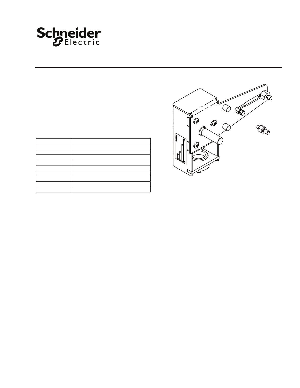
Application
The AV-611 linkage is designed to link the Schneider
Electric SmartX Actuators Mx41-6xx3 (non-spring
return) and Mx40-704x (spring return) shown in Table-1
to 1/2” through 2” VB-7xxx and 1/2” through 1-1/4”
discontinued VB-9xxx 2-way and 3-way globe valves.
Table-1 Actuators
Actuator Descriptions
MF41-6043 Floating 35 lb-in non-spring return
MS41-6043 Proportional 35 lb-in non-spring return
MF41-6083 Floating 70 lb-in non-spring return
MS41-6083 Proportional 70 lb-in non-spring return
MF41-6153 Floating 133 lb-in non-spring return
MS41-6153 Proportional 133 lb-in non-spring return
MA40-704x Two-position 35 lb-in spring return
MF40-7043 Floating 35 lb-in spring return
MS40-7043 Proportional 35 lb-in spring return
AV-611
SmartX Actuator
Globe Valve Linkage
General Instructions
Applicable Literature
• Mx41-6043, Mx41-6083 Series non-spring return
actuator General Instructions, F-27213.
• Mx41-6153 Series Non-spring return actuator
General Instructions, F-27215.
• MA40-704x, MA4x-707x, MA4x-715x Series spring
return actuator General Instructions, F-26642.
• MF40-7043, MF4x-707x, MF4x-715x Series spring
return actuator General Instructions.
• Vx-7000 & Vx-9000 Series Mx41-6xxx & Mx4x-7xxx
Series Linked Globe Valve Assemblies Selection
Guide, F-26752.
• VB-7211 Series Valve Body General Instructions,
F-24380
• VB-7212 Series Valve Body General Instructions,
F-24381.
• VB-7213 Series Valve Body General Instructions,
F-26075.
• VB-7214 Series Valve Body General Instructions,
F-25675.
• VB-7221 Series Valve Body General Instructions,
F-24384.
• VB-7222 Series Valve Body General Instructions,
F-24385.
• VB-7223 Series Valve Body General Instructions,
F-26073.
• VB-7224 Series Valve Body General Instructions,
F-25387.
• VB-7225 Series Valve Body General Instructions,
F-26079.
• VB-7312 Series Valve Body General Instructions,
F-24392.
• VB-7313 Series Valve Body General Instructions,
F-26074.
• VB-7314 Series Valve Body General Instructions,
F-24394.
• VB-7315 Series Valve Body General Instructions,
F-26078
• VB-7323 Series Valve Body General Instructions,
F-26076.
• VB-7215 Series Valve Body General Instructions,
F-26077.
Schneider Electric
F- 27410 -3 May 2014
• VB-7332 Series Valve Body General Instructions,
F-24396.
Page 2

INSTALLATION
2
Inspection
Requirements
Mounting
Inspect the package for damage. If damaged, notify the appropriate carrier immediately. If
undamaged, open the package and inspect the device for obvious damage. Return any
damaged products.
• Training: Installer must be a qualied, experienced technician.
• Tools (not provided):
– Appropriate wrenches for stem extensions, packing nuts, and bracket nuts
– 10 mm socket wrench (for shaft clamp nuts on Mx41-6153 and Mx40-704x)
– Torque wrench, range to include 60 to 120 lb.-in. (6.8 to 14 N-m)
– Pipe wrenches, two
– TOOL-37, 1-5/8 inch open-end wrench for valve mounting nut
– 5/16” open-end wrench for jam nuts (or TOOL-20-1 or equivalent)
– Vise grip or pliers
– Appropriate power supply (see the applicable actuator General Instructions sheet
for power requirements)
Warning:
• Disconnect the power supply (line power) before installation to prevent equipment
damage.
• Make all connections in accordance with the job wiring diagram and in accordance with
national and local electrical codes. Use copper conductors only.
Allow at least 5” (127 mm) above the actuator/linkage assembly for removal and
reattachment of the actuator to the installed valve.
Assembling Actuator
and Linkage to Valve
Body
Process Overview
This assembly procedure consists of two sections:
• Section A. Assembling Linkage to Valve — All Valve Types and Actuator Models
For all actuator models and valve types (2-way and 3-way), follow the instructions in
this section to assemble the linkage to the valve.
• Section B. Actuator Mounting and Setup
In this section, choose the subsection that is appropriate for the specic actuator type
and valve type, to mount the actuator and adjust the linkage:
– B1. Mx41-6043 and Mx41-6083 Non-spring Return Actuators with Manual
Override — 2-Way (Stem Up Open, Stem Up Closed) and 3-Way Valves
These instructions apply to actuators with manual override, to be mounted onto
2-way valves (stem up closed and stem up open) and 3-way valves
– B2. Mx41-6153 Non-Spring Return Actuators with Manual Override — 2-Way
Valves (Stem Up Closed and Stem Up Open) and 3-Way Valves
These instructions apply to actuators with manual override, to be mounted onto
2-way valves (stem up closed and stem up open) and 3-way valves.
– B3. Mx40-704x Spring Return Actuators without Manual Override — 2-Way
Valves (Stem Up Closed and Stem Up Open)
These instructions apply to spring return actuators, to be mounted onto 2-way
valves (stem up closed and stem up open).
– B4. Mx40-704x Spring Return Actuators without Manual Override — 3-Way
Valves
These instructions apply to spring return actuators, to be mounted onto 3-way
valves.
Refer to Table‑2, on the next page, to determine the assembly path for the specic actuator
and valve.
Schneider Electric
F- 27410 -3 May 2014
Page 3
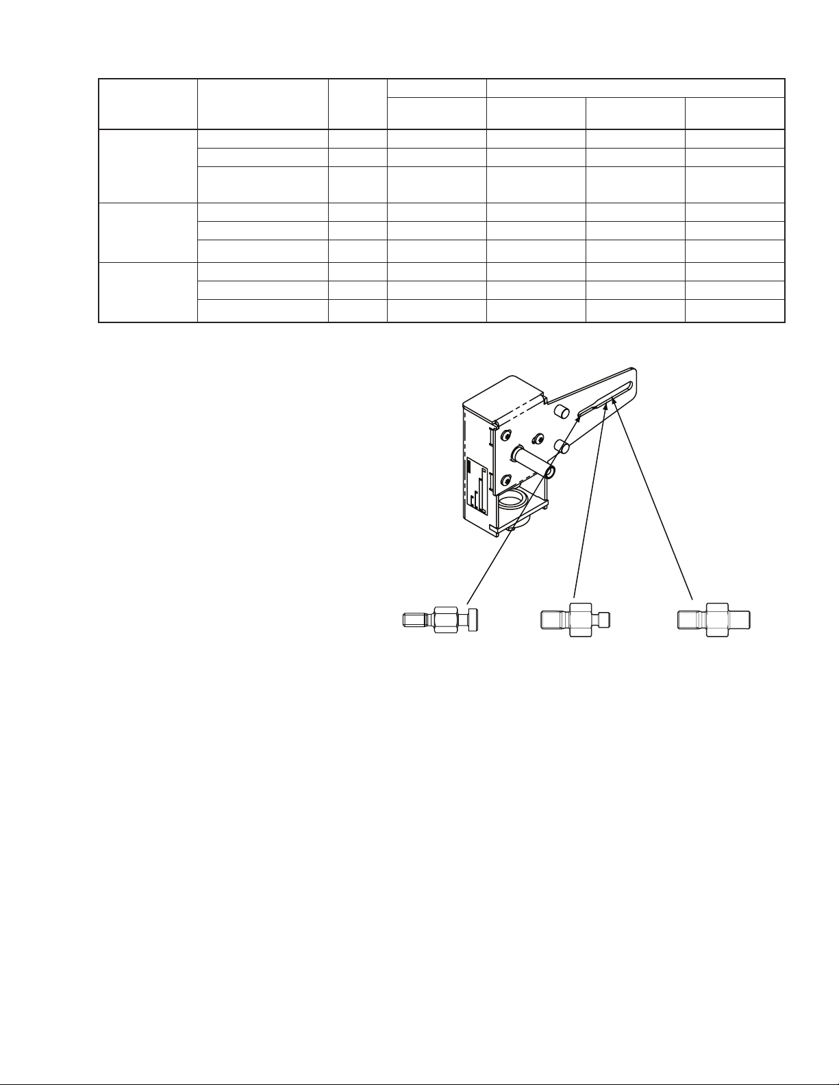
Table-2 Assembly Process for Mounting Actuator and Linkage to Valve Body.
NYBA-206
Anti-Rotation Stud fo
r
Mx41-6153
NYBA-161
Anti-Rotation Stud for
Mx40-704x
NYBA-173
Anti-Rotation Stud for
Mx41-6043, Mx41-6083
Insert in
Narrow Slot
Insert in
Wide Slot
Actuator
Type
Non-spring Return
Actuators with
Manual Override:
Mx41-6043
Mx41-6083
Non-spring Return
Actuators with
Manual Override:
MX41-6153
Spring Return
Actuators without
Manual Override:
MX40-704X
Valve Type Section A
Subsection
B1
Subsection
B2
2-Way Stem-Up Open X X
2-Way Stem-Up Closed X X
3-Way X X
2-Way Stem-Up Open X X
2-Way Stem-Up Closed X X
3-Way X X
2-Way Stem-Up Open X X
2-Way Stem-Up Closed X X
a
3-Way
X X
Section B
Subsection
B3
3
Subsection
B4
Schneider Electric
F- 27410 -3 May 2014
Figure-1 Anti-Rotation Studs.
Page 4
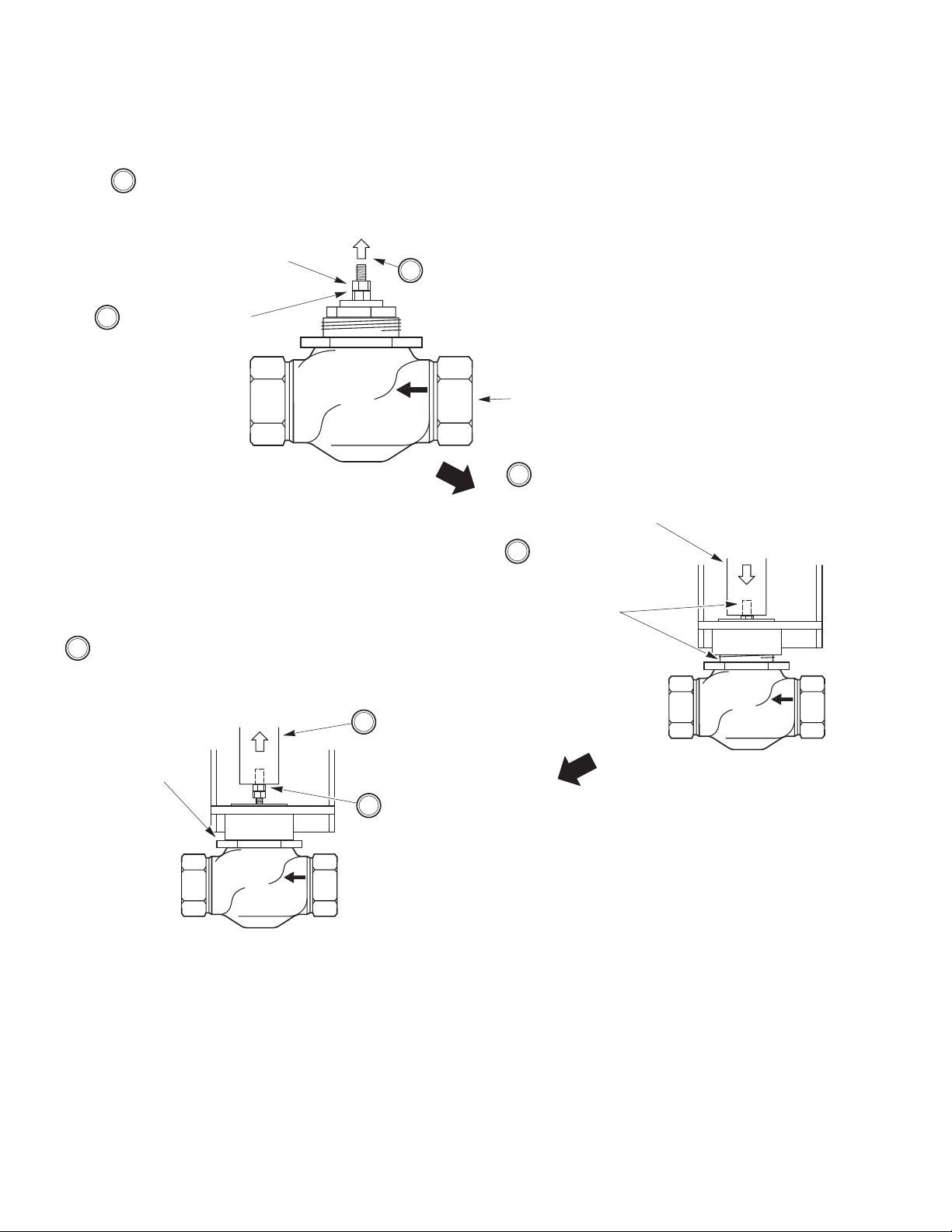
Typical Valve Body
(2-Way shown)
1 Locate and remove the two
jam nuts taped to the
linkage housing, then screw
the nuts to the bottom of the
valve stem (at least 1/4" of
the stem should extend
above the top nut).
2 Tighten the jam
nuts against each
other, using two
5/16" open-end
wrenches (or
TOOL-20-1 or
equivalent).
3 Raise the valve
stem to the full
up position.
4 Rotate the pinion shaft
CW to fully lower the
rack, and then position
the linkage over the
valve stem.
5 Fully thread the
linkage rack onto
the valve stem until
it contacts the jam
nuts (do not
tighten), then
engage the valve
mounting nut in the
linkage adaptor (do
not tighten).
7 Rotate the pinion
shaft CCW to raise
the rack and expose
the jam nuts.
6 Orient the
linkage on the
valve as desired,
and then tighten
the valve
mounting nut
against the
linkage adaptor,
using TOOL-37.
8 Tighten the jam
nuts against the
rack, using a 5/16"
open-end wrench
on the lower jam
nut (or TOOL-20-1
or equivalent).
Figure-2 Assembling Linkage to Valve.
Section A. Assembling Linkage to Valve — All Valve Types and Actuator
4
Models
1. If necessary, remove unused anti-rotation studs from linkage (see Figure-1 on page 3)
2. Assemble the linkage to the valve, according to Figure-2.
Schneider Electric
F- 27410 -3 May 2014
3. Continue the assembly process according to the following section, “Section B. Actuator
Mounting and Setup.”
Page 5
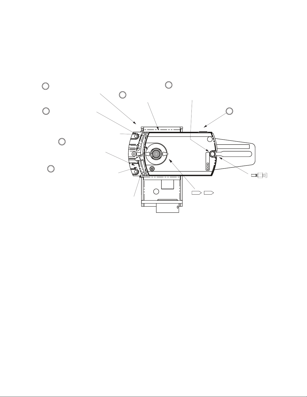
Section B. Actuator Mounting and Setup
Valve Stroke Up Dash Mark
Valve Stroke Down Dash Mark
3 Align the actuator with
the mounting plate.
2 Slide the actuator onto the
linkage's pinion shaft.
1 Rotate the linkage's pinion shaft
CCW, to retract the rack (stem up).
4 Slide the anti-rotation stud half
way into the slot on the bottom of
the actuator, then tighten the nut
on the anti-rotation screw.
5 Hold down the manual
override button.
6 Point the positioning
lever towards the
"valve stroke up" hole.
7 Make sure the actuator is in full
contact with the plastic stand-offs on
the linkage, and then use a 7/32"
hex wrench to tighten the set screw
55 to 60 lb-in. (6.2 to 6.8 N-m).
Optional: Affix the Open and
Closed labels to the indicator in
the appropriate positions.
OPENCLOSED
NYBA-173
Anti-Rotation Stud for
Mx41-6043, Mx41-6083
(in narrow slot of linkage)
To mount the actuator and set up the assembly, refer to the subsection that applies to the specic
actuator type and valve type.
B1. Mx41-6043 and Mx41-6083 Non-spring Return Actuators with Manual Override —
2-Way (Stem Up Open, Stem Up Closed) and 3-Way Valves
a. Conrm that the NYBA‑173 anti‑rotation stud is installed in the narrow slot of the
linkage (refer to Figure-1 on page 3). Install the actuator onto the linkage and valve and
set up the assembly as shown in Figure-3.
5
Figure-3 Mounting Mx41-6043 and Mx41-6083 Actuators and Setting Up Actuator/Linkage/Valve Assembly
Schneider Electric
F- 27410 -3 May 2014
b. Apply power to the actuator and check the system’s operation for heating or cooling
output in response to the control signal.
c. Refer to the appropriate actuator General Instructions sheet for actuator wiring and
application information. For valve body installation and application information, refer to
the appropriate valve body General Instructions sheet. Refer to “Applicable Literature”
on page 1.
Page 6
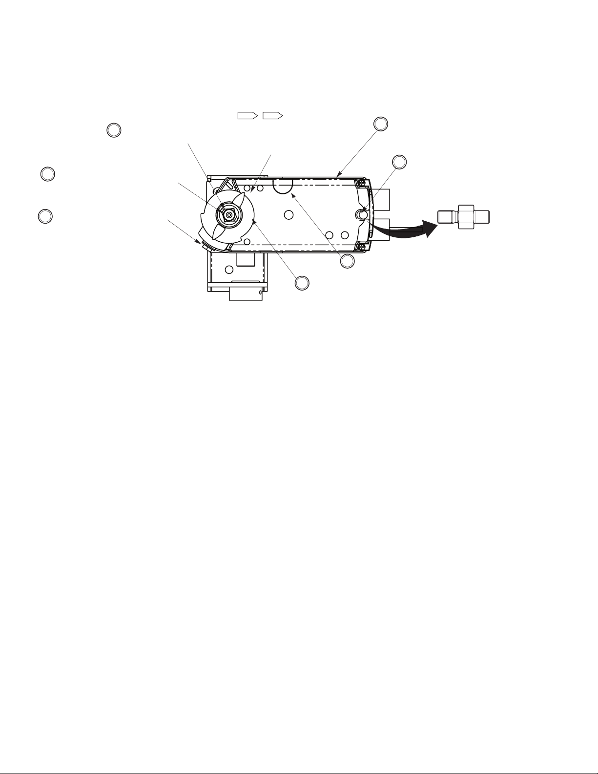
B2. Mx41-6153 Non-Spring Return Actuators with Manual Override — 2-Way Valves
2 Slide the actuator onto the
linkage's pinion shaft.
Optional: Affix the Open and
Closed labels to the indicator
in the appropriate positions.
OPENCLOSED
7 Make sure the actuator is in full
contact with the plastic stand-offs
on the linkage, then use an 18
mm wrench or socket to tighten
the shaft clamp nut 90 to 108 lbin (10 to 12 N-m). Do not overtighten.
6 Position the actuator output
shaft at 10° from CCW end
of travel.
4 Slide the anti-rotation stud half
way into the slot on the bottom of
the actuator, and then tighten the
nut on the anti-rotation screw.
1 Rotate the linkage's pinion shaft
CCW, to retract the rack (stem up).
3 Align the actuator with
the mounting plate.
5 Hold down the manual
override button.
NYBA-206
Anti-Rotation Stud for
Mx41-6153
(in wide slot of linkage)
(Stem Up Closed and Stem Up Open) and 3-Way Valves
a. Conrm that the NYBA‑206 anti‑rotation stud is installed in the wide slot of the
linkage (refer to Figure-1 on page 3). Install the actuator onto the linkage and
valve, and set up the assembly, according to Figure-4 below.
6
Figure-4 Mounting Mx41-6153 and Setting up Actuator/Linkage/Valve Assembly.
b. Apply power to the actuator and check the system’s operation for heating or
cooling output, in response to the control signal.
c. Refer to the appropriate actuator General Instructions sheet for actuator wiring and
application information. For valve body installation and application information,
refer to the appropriate valve body General Instructions sheet. Refer to “Applicable
Literature” on page 1.
Schneider Electric
F- 27410 -3 May 2014
Page 7
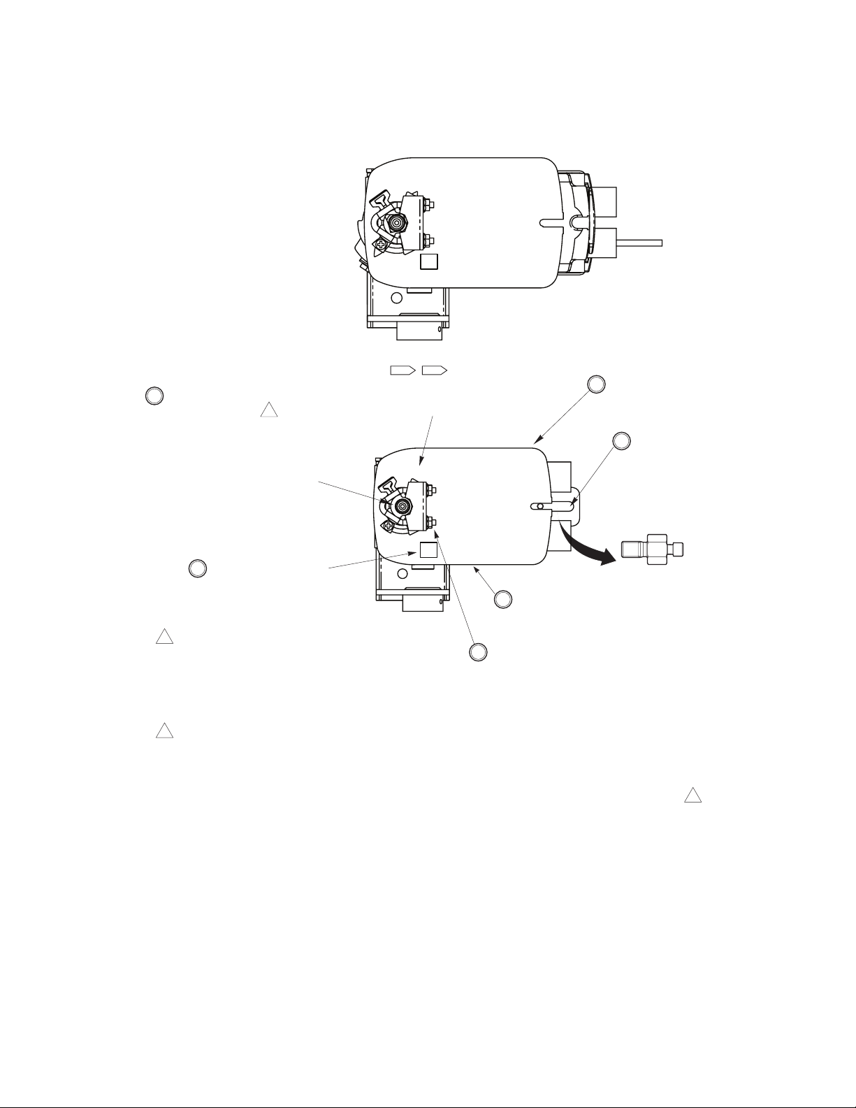
B3. Mx40-704x Spring Return Actuators without Manual Override — 2-Way Valves
1 Caution: When used on a VB-9xxx or similar 1/2" to 1-
1/4" (15 mm to 32 mm) valve body, push the valve
stem all the way down and adjust the rack to get at
least 1/32" (1 mm) clearance above the top of the
packing. Use only 35 lb-in. (4 N-m) Mx40-704x
actuators on obsolete valves. Stem or plug damage
may result from using actuators with higher output
torques.
2 Tip:
• MA40-704x Two-Position - When power is applied
(L1, L2), the actuator will travel to the end of stroke.
• MF40-704x Floating Control - Connect the blue lead
to the red lead, and then apply power (L1, L2) to
drive the actuator to the end of stroke.
• MS40-704x Proportional Control - Change the
reversing switch setting from direct acting (L) to
reverse acting (R),then apply power to drive the
actuator to the end of stroke. When finished, return
the switch setting to direct acting (L).
Optional: Affix the Open and
Closed labels to the indicator
in the appropriate positions.
OPENCLOSED
2 Slide the actuator, "L" side
facing out, onto the linkage's
pinion shaft.
1 Rotate the linkage's pinion shaft to the
valve open position:
• Stem Up Open Valves - Rotate the
pinion shaft CCW to retract the linkage
rack to the up position.
• Stem Up Closed Valves - Rotate the
pinion shaft CW to extend the linkage
rack to the down position.
3 Align the actuator with the
linkage.
4 Slide the anti-rotation stud
half way into the slot on
the bottom of the actuator,
and then tighten the nut
on the anti-rotation screw.
5 Make sure the actuator is in
full contact with the plastic
stand-offs on the linkage.
6 Lightly finger-tighten the two nuts on the shaft clamp, and
then set up the actuator and tighten the shaft clamp as
follows:
For Normally Open Operation, Stem Up Open Valves
a. Verify that the linkage rack is still in the full up position.
b. Using a 10 mm wrench or socket, torque the nuts equally
on the shaft clamp, 8 to 10 lb-ft (11 to 14 N-m). The
actuator is now in the open position, without power.
For Normally Closed Operation, Stem Up Closed Valves
a. Power the actuator to the end of stroke (see the
applicable actuator General Instructions).
b. Verify that the linkage rack is still in the full down position.
c. Using a 10 mm wrench or socket, torque the nuts equally
on the shaft clamp, 8 to 10 lb-ft (11 to 14 N-m). The
actuator is now in the open position, at the end of stroke.
2
1
NYBA-161
Anti-Rotation Stud for
Mx40-704x
(in wide slot of linkage)
L
L
(Stem Up Closed and Stem Up Open)
a. Conrm that the NYBA‑161 anti‑rotation stud is installed in the wide slot of the
linkage (refer to Figure-1 on page 3). Install the actuator onto the linkage and
2-way valve, and set up the assembly, according to Figure-5 below.
7
Figure-5 Mounting Mx40-704x on 2-Way Valves and Setting up Actuator/Linkage/Valve Assembly.
Schneider Electric
F- 27410 -3 May 2014
b. Apply power to the actuator and check the system’s operation for heating or
cooling output, in response to the control signal.
c. Refer to the appropriate actuator General Instructions sheet for actuator wiring and
application information. For valve body installation and application information,
refer to the appropriate valve body General Instructions sheet. Refer to “Applicable
Literature” on page 1.
Page 8
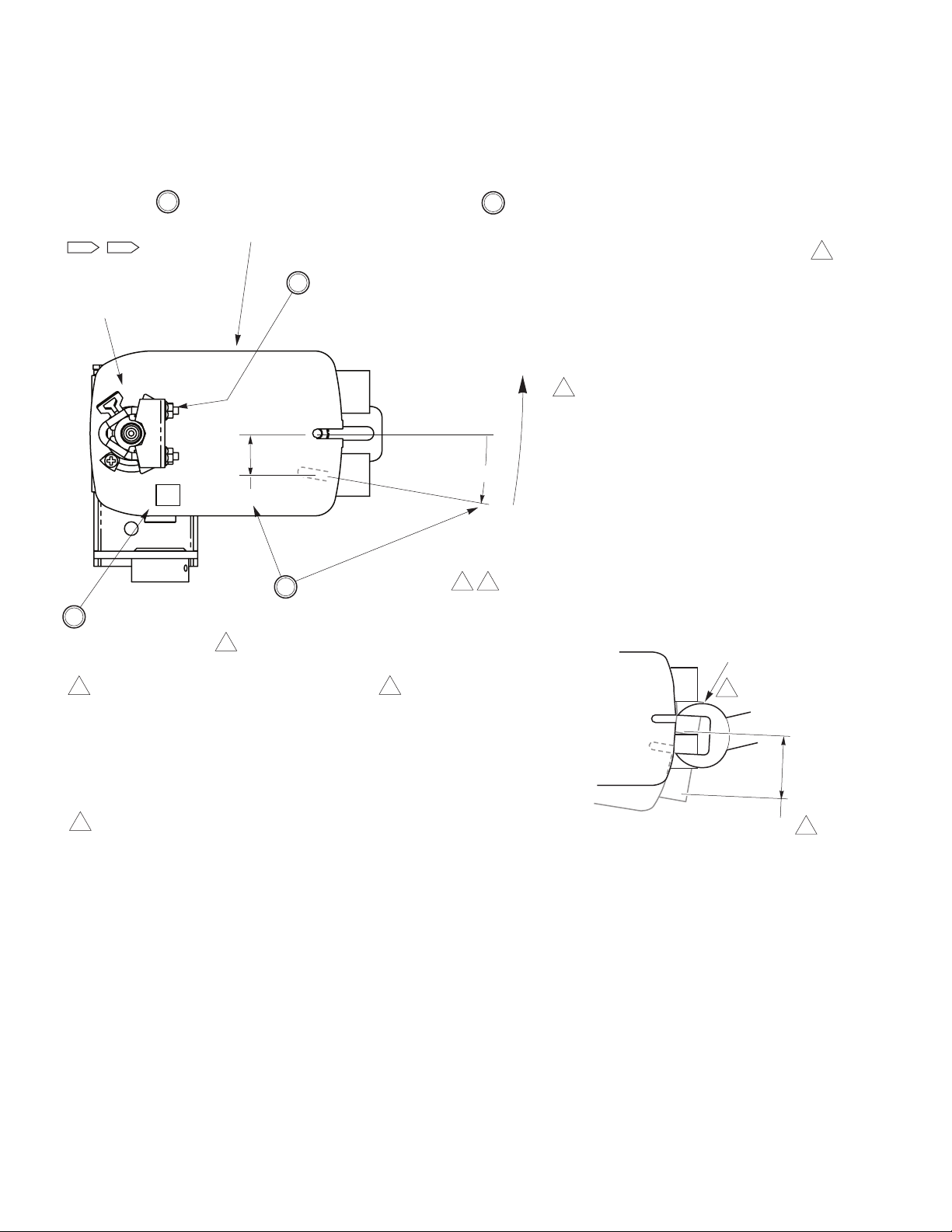
B4. Mx40-704x Spring Return Actuators without Manual Override — 3-Way Valves
4 Tip:
• MA40-704x Two-Position - When power is
applied (L1, L2), the actuator will travel to
the end of stroke.
• MF40-704x Floating Control - Connect the
blue lead to the red lead, and then apply
power (L1, L2) to drive the actuator to the
end of stroke.
• MS40-704x Proportional Control - Change
the reversing switch setting from direct
acting (L) to reverse acting (R), and then
apply power to drive the actuator to the end
of stroke. When finished, return the switch
setting to direct acting (L).
2 Mx40-704x actuators are shipped at the end of
stroke, without preload.
3 Make sure the actuator is in
full contact with the plastic
stand-offs on the linkage.
Optional: Affix the Open
and Closed labels to the
indicator in the appropriate
positions.
OPENCLOSED
1-1/8"
10°
3
3
1-3/8"
4
5 Apply power to the actuator to rotate it CCW into
alignment with the mounting plate,then slide the antirotation stud halfway into the slot on the bottom of the
actuator. Tighten the nut on the anti-rotation screw.
Warning: Take care not to pinch your fingers or hand
between the actuator and the mounting plate, when
powering the actuator into alignment.
Caution: When setting the valve preload, power must be
used to position the actuator. Do not manually force the
actuator into the mounting position. If forced, damage to
the pinion shaft or improper close-off may occur.
3 Tip: A 1-3/8" open-end wrench can
be used to measure the amount of
rotation (approx. 10°, measured
between opposite sides of the slot).
4 Holding the actuator at the 10°
position, use a 10 mm wrench or
socket to tighten the two nuts
equally on the shaft clamp, 8 to
10 lb-ft (11 to 14 N-m).
1 Slide the actuator, "L" side
facing out, onto the
linkage's pinion shaft.
213
2 Align the actuator with the
mounting plate, then rotate it 10°
CW. Note that 1-1/8" movement
at the anti-rotation slot (measured
at anti-rotation slot's centerline) is
sufficiently equal to 10°.
1 Caution: When used on a VB-9xxx or similar
1/2" to 1-1/4" (15 mm to 32 mm) valve body,
push the valve stem all the way down and
adjust the rack to get at least 1/32" (1 mm)
clearance above the top of the packing. Use
only 35 lb-in. (16 N-m) Mx40-704x actuators
on obsolete valves. Stem or plug damage may
result from using actuators with higher output
torques.
1-3/8" Open-End
Wrench
L
a. Conrm that the NYBA‑161 anti‑rotation stud is installed in the wide slot of the
linkage (refer to Figure-1 on page 3).Install the actuator onto the linkage and 3-way
valve, and set up the assembly, according to Figure-6 below.
Figure‑1Mounting Mx40-704x on 3-Way Valves and Setting up Actuator/Linkage/Valve Assembly.
b. Apply power to the actuator and check the system’s operation for heating or
cooling output, in response to the control signal.
c. Refer to the appropriate actuator General Instructions sheet for actuator wiring and
application information (see “Applicable Literature (contd)” on page 2). For valve
body installation and application information, refer to the appropriate valve body
General Instructions sheet.
Schneider Electric
F- 27410 -3 May 2014
© 2014 Schneider Electric. All rights reserved.
 Loading...