

Page 1
APPLICATION
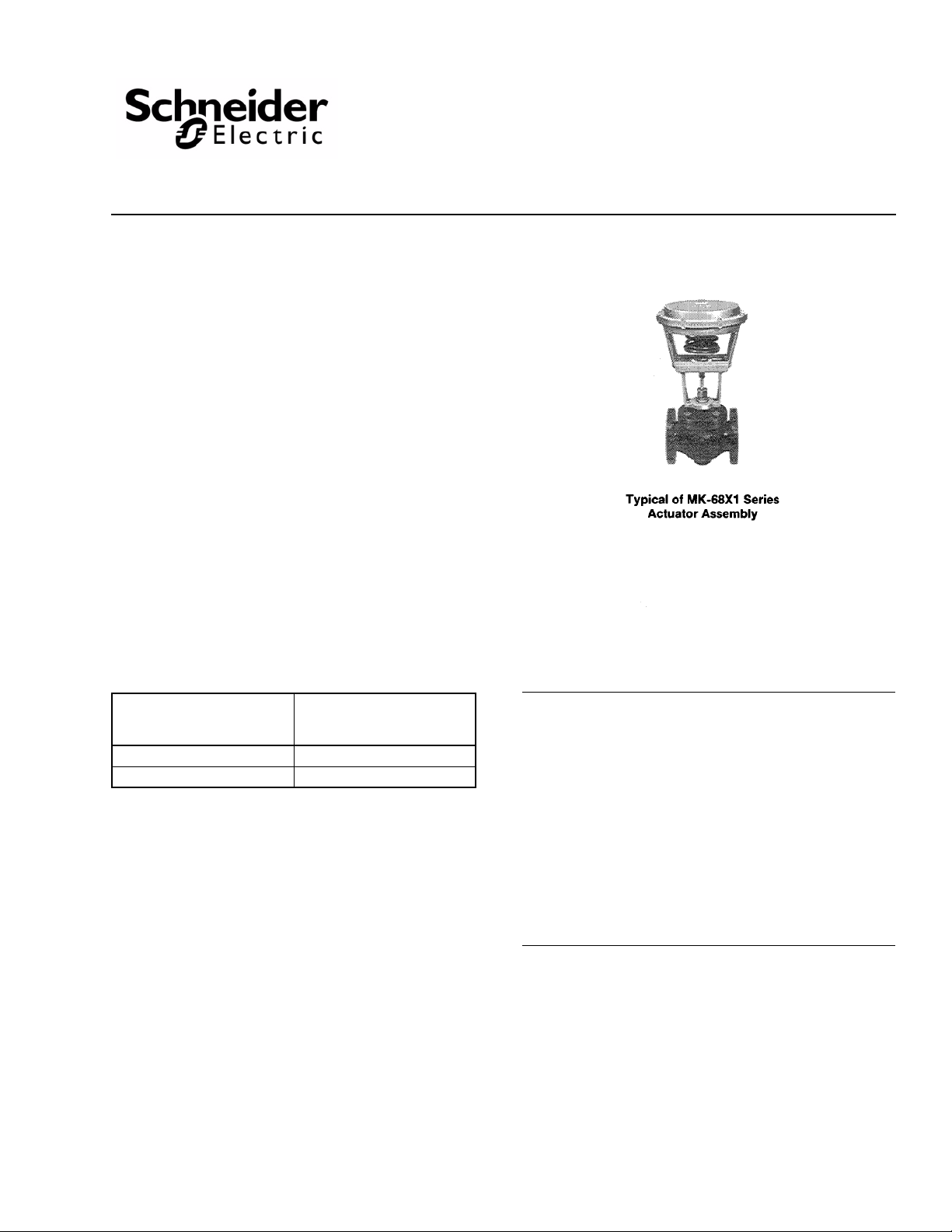
The AV-495 linkage is used to field install MK-68X1series of
actuators 2-1/2" to 4" VB-9213, VB-9223 and VB-9313
Schneider Electric valve bodies. Table-1 provides a list of
actuators and valves compatible with AV-495 and details
resulting close-off pressure.
PRE-INSTALLATION
Inspection
Visually inspect the package for damage. If damaged, notify
the appropriate carrier immediately. If undamaged, open the
package and visually inspect the device for obvious defects.
Return damaged or defective products.
AV-495
Valve Linkage
General Instructions
Required Installation Items
Tools (not provided):
• Appropriate wrenches for stem extensions, lock nuts and
mounting bolts.
Table-1 Restrictions on Maximum Ambient Temperature
For The Valve Actuator.
Max. Temperature in °F (°C)
of Media in the Valve Body
(Check Ratings of the Valve)
281 (138) 160 (71)
250 (121) 220 (104)
Max. Ambient Temperature in
°F (°C) of MK-6801, MK-6811
or MK-6821
INSTALLATION
Consult Table-1 to make sure the valve selected is compatible
with AV-495 valve linkage and the actuator. Verify that the
close-off pressure shown in Table-1 is adequate for the
application. Verify that fluid temperature of the media in the
valve versus the ambient temperature at the actuator do not
exceed the ratings shown in Table-2.
Caution:
• Installer must be a qualified, experienced technician
• Avoid locations where excessive moisture, corrosive
fumes or vibration are present.
• Install all two-way valves so that they close against the
flow. An arrow on the valve body or a tag indicates the
proper flow direction.
• Always install three-way mixing valves with two inlets and
one outlet.
• The actuators can be mounted in any position above the
centerline of the valve body. When selecting a location,
allow sufficient room for accessories and for service of
the product.
Printed in U.S.A. 11-10 © Copyright 2010 Schneider Electric All Rights Reserved. F-21665-8
Page 2

Table-2 Actuators and Valve Bodies That are Compatible with AV-495 and Resulting Close-off Pressure.
MK-6801 MK-6811 MK-6821
Valve Body Information
Close-Off Pressure (psi)
Supply Air Pressure (psig)
Valve Body Part
Number
Description
VB-9213-0-4-12 2-Way
VB-9213-0-4-13 Open 85 3 - 41 75 - 27 62 - 5 41
250 psi Globe
Screwed
VB-9213-0-5-12
VB-9213-0-5-13 Open 85 3 - 41 75 - 27 62 - 5 41
2-Way
125 lb. Flanged
Normal
Position
(Stem Up)
Cv
Size
(in.)
SU
Open 65 2-1/2 - 60 110 - 40 91 - 9 60
Open 56 2-1/2 - 60 110 - 40 91 - 9 60
SD
15 20 15 20 15 20
SU
SD
VB-9213-0-5-14 Open 145 4 - 22 41 - 14 33 - 2 22
VB-9223-0-4-12 2-Way
VB-9223-0-4-13 Closed 85 3 5 - - 19 - - 41 - -
250 psi Globe
Screwed
VB-9223-0-5-12
VB-9223-0-5-13 Closed 85 3 5 - - 19 - - 41 - -
2-Way
125 lb. Flanged
Closed 65 2-1/2 9 - - 30 - - 60 - -
Closed 56 2-1/2 9 - - 30 - - 60 - -
VB-9223-0-5-14 Closed 145 4 2 - - 10 - - 22 - -
VB-9313-0-4-12
3-Way Mixing
250 psi Globe
VB-9313-0-4-13
Screwed
VB-9313-0-5-12
VB-9313-0-5-13
3-Way Mixing
125 lb. Flanged
VB-9313-0-5-14
a
Close-off pressure for 3-way valves:
SU is “A” port close-off and is based on pressure at “A” port minus pressure at “B” port.
SD is “B” port close -off and is based on pressure at “B” port minus pressure at “A” port.
SU = Stem up position of valve.
SD = Stem down position of valve.
Flow B to
AB
Flow B to
AB
Flow B to
AB
Flow B to
AB
Flow B to
AB
67 2-1/2 9 60 110 30 40 91 60 9 60
91 3 5 41 75 19 27 62 41 5 41
74 2-1/2 9 60 110 30 40 91 60 9 60
101 3 5 41 75 19 27 62 41 5 41
170 4 2 22 41 10 14 33 22 2 22
a
SD
SU
2 © Copyright 2010 Schneider Electric All Rights Reserved. F-21665-8
Page 3

To install AV-495 Valve Linkage on Current Style
Valves (Valves that do not require removal of
packing nut to mount the actuator)
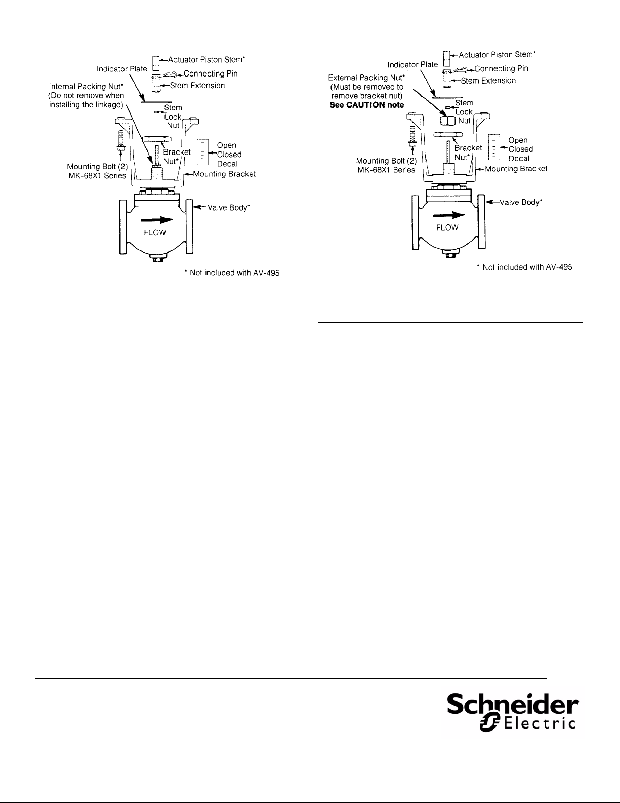
Refer to Figure-1.
1. Mount the bracket on the valve body by removing the
bracket nut, placing the bracket on the valve body and
replacing and tightening the valve bracket nut.
Note: Position the bracket so that the wiring or piping of the
actuator is convenient.
2. Thread the 1/2" lock nut well down onto the valve stem.
Place the indicator plate on the valve stem. Thread the
stem extension well down onto the valve stem.
3. Attach the actuator to bracket:
MK-68X1 series actuator: Use the two (2) bolts provided
to fasten the actuator to the mounting bracket.
4. Stem height adjustment. See Table-3.
5. Tighten the lock nut against the stem extension to make
the stem extension secure to the stem.
6. Apply the OPEN/CLOSED decal - 1" scale length.
To Install AV-495 Valve Linkage on Obsolete Style
Valves (Valves that require removal of packing nut
to mount the actuator)
Refer to Figure-2.
Table-3 Stem Height Adjustment.
Val ve Ty p e
2-Way Normally
Open
2-Way Normally
Closed, 3-Way
Valve Body
Part Number
Series
VB-9213
VB-9223
VB-9313
Procedure to Adjust Stem Extension and Insert Connecting Pin
1. The actuator should be powered and manually positioned so that actuator piston shaft is fully
extended.
2. The valve stem should be pushed completely down with the valve disc against the valve seat.
3. The stem extension should be turned until the hole in the stem extension aligns with hole in
the actuator piston.
4. Turn the stem extension two full turns up into the actuator piston.
5. Manually position the actuator toward the retract position and insert connecting pin.
1. The actuator should be in its fully retract position (no power).
2. The valve stem should be pulled completely up with the valve disc against the top valve seat.
3. The stem extension should be turned until the hole in the stem extension aligns with hole in
the actuator piston.
4. Turn the stem extension down two full turns away from the actuator piston.
5. Manually position the actuator toward the extend position and insert connecting pin.
Caution: Before the packing nut is removed, the system
pressure on the valve must be reduced to 0 psig. If the
packing nut is removed while there is pressure on the valve,
the packing can blow out of the valve.
1. Mount the bracket on the valve body by removing the
packing nut and the bracket nut, placing the bracket on the
valve body and replacing and tightening the valve bracket
nut and subsequently replacing the packing nut.
Note: Position the bracket so that the wiring or piping of the
actuator is convenient.
2. Thread the 1/2" lock nut well down onto the valve stem.
Place the indicator plate on the valve stem. Thread the
stem extension well down onto the valve stem.
3. Attach the actuator to the bracket:
MK-68X1 series actuator: Use the two (2) bolts provided
to fasten the actuator to the mounting bracket.
4. Stem height adjustment: See Table-3.
5. Tighten the lock nut against the stem extension to make
the stem extension secure to the stem.
6. Apply the OPEN/CLOSED decal - 1" scale length.
F-21665-8 © Copyright 2010 Schneider Electric All Rights Reserved. 3
Page 4
On October 1st, 2009, TAC became the Buildings business of its parent company Schneider Electric. This document reflects the visual i d en tity of Schneider Electric,
however there remains ref erences to TAC as a corporate brand in the b ody copy. As each docume nt is updated, the body copy will be changed to reflect app r opriat e
Figure-1 Valve Linkage Assembly for MK-68X1 Series of
Actuators with Current 2-1/2" to 4" VB-9XXX Valve Bodies.
Figure-2 Valve Linkage Assembly for MK-68X1 Series of
Actuators with Obsolete 2-1/2" to 4" VB-9XXX Valve Bodies.
Caution: Before the packing nut is removed, the system pressure
on the valve must be reduced to 0 psig. If the packing nut is
removed while there is pressure on the valve, the packing can
blow out of the valve.
corporate brand changes.
Copyright 2010, Schneider Electric
All brand names, trademarks and registered
trademarks are the property of their respective
owners. Information contained within this
document is subject to change without notice.
F-21665-8
 Loading...